Realised I posted this query in the wrong place.
Title should be repair, upgrade or replace amp boards.
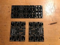
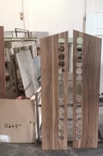
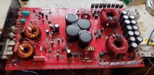
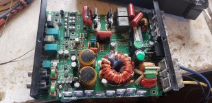
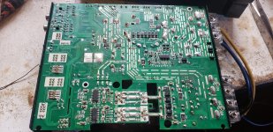
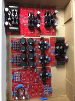
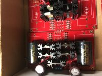
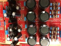
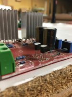
The darlingtons (mj11015/6)on my Virtuoso power amp have failed and I'm considering replacing the amp boards for something more modern and better than the Virtuoso. It's an old design by Graham Nalty in ETI with loads of esoteric components, holco h8 and h2 resistors, Mat02 (ssm2201) transistor pairs, wonder caps. I've added schottky diodes, silver wire and kimber cable etc.
The power rails are +-56v dc with a separate regulated supply for the low power gain stages.
To put it into context, it's current build it is better than a rotel rb-991(more air and detail) and recently caused a friend to upgrade his Naim 140s. I haven't had the chance to compare it with anything else recently. My friend was supposed to bring his naim 250? over but covid got in the way....plus I blew my amp up


Alternatively I could consider alternative better darlingtons or mosfets (the amp was also designed to allow mosfets RFM10N15/P15 to be used with the removal of some parts and adding gate resistors.)
I was looking at faster darlingtons or the exicon mosfets but to tell the truth I have little idea on what other changes to ensure that they will work.
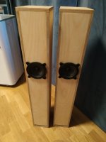
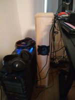
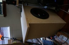
It also needs to be able to drive my Martin Logan Sequel IIs and handle all genres of music from classical, folk, blues to rock as I listen to all good music irrespective of "designation"!
Pre-amp is Versatile LDR designed by Rudi_Ratio who kindly posted his design and organised a group buy on this forum. Sounds Great!! Thanks also to George who did the groundwork for LDR preamps.
Any advice or suggestions appreciated.

 Split from
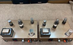


