Alan's TU-8600


Alan’s TU-8600


Hello Victor,

It’s been a bit more than 6 months since I reinstalled the main board after my power issues. Thought it was a good time to give you a report. The Psvane WEs are fantastic. After you recommended a Telefunkin 12AX7 about a year ago, I looked through my tube inventory and found another highly regarded 12AX7, an Amperex Bugle Boy. Another big improvement.
About 3 months ago, I added RCA Clear Top 12AU7s .

All in all, the upgraded TU-8600 is an amazing amp. I think Herb Reichart was totally right!

Best regards,

Alan

Advice needed for TPA3118 Power Supply

Hi guys first of all this is only my 3rd post here, i've been a (very) silent but loyal reader here 😀
and i'm not a native speaker so bear with me..

here goes,
i just bought 2 pieces of Sanwu blue board clone (monoblock tpa 3118) mostly because they're dirt cheap and i've read rave reviews about them relative to their price and size
now i need the power supply to.. well supply power to them 😀

the easiest way would be to just bought a switcher be it a meanwell clones (which is unreliable to say the least) or a laptop brick supply.
"real" meanwell, omron, or astec are way out of my budget and i don't feel like spending too much for this little side project

now i happen to have 2 identical smallish transformers, it's a center tap with multiple secondaries on it and i think its capable for about 3 amp on the highest tap (35 Vac). i'm thinking of using one for each board.

and i also have a regulated power supply board which based on a linear regulator with pass transistor but it's different than any schematic i found on the net
this is the schematic for the pcb that i have

attachment.php


is that usable or should i just forget it and use this instead

attachment.php


the buck converter would be one of those xl4016 based module with 8A 200watt maximum output, more than enough to power one board or even two

so what do you guys think?
it's a cheap and cheerful project and like i said i don't want to spend too much on it (my SymAsym still needs a lot of TLC), and besides i already have most of the parts for the two plans above except the buck converter which is cheap enough.

Attachments

  • 1.jpg
    1.jpg
    41.8 KB · Views: 323
  • 2.jpg
    2.jpg
    32.9 KB · Views: 275

Powering soft start with PC's 12v Rails

I need to build a relay based power on circuit for my amplifiers that is powered by my PC's 12v output rails. I have a couple of amplifiers that I want power on/ off along with my PC as it turns on and off . Its quite convenient that the PC provides a 12v rail that power on and off along with the PC, it even allows for a power off state in sleep mode, which is exactly what I need. ie amplifiers turn off when PC goes to sleep.

Given that it will power 2 amplifiers (4 toroids 400VA each) will also need a soft start / delay capability. So a straight relay powered by the 12v rails alone will not do. It must be a 2 step (ie soft start) that is triggered by the 12v generated by the PC's power supply. ie no manual on/ off switch is needed.

I have several relays / SSR's available and basic components. Does anyone have a simple schematic I can use (no active devices in the circuit please, I don't want to buy mosfets or worry about mounting them etc.). Just LCR components with perhaps a diode or 2 as needed.

I have power resistors or Thermisters also available.

Anyone have a simple schematic I can build?

I have the following components:

- 12v relays
- 12v SSR's
- 1/4 watt resistors (many)
- 1A diodes
- 30 ohm 50w power resistors (8 of them)
- 1 ohm power resistor 50w (8 of them)

I'd like to avoid using thermisters/ mosfets/ bjts (basically anything that can increase complexity / reduce reliability)

Another Adcom GFA 555 repair request

Hi guys,

i bought old Adcom GFA 555 mkI.
It must be cleaned, so i did, replaced electrolytics on PCB.

With service manual bias is set to 16-18mA.

But on left channel i have full DC +76V.

I measured with RLC meter all transistors of amplifier and i didnt find faulty one. I pulled out and measure one by one.

Right channel is working fine.

I could measure and compare channels.

Could anyone give me some help tips? :worship:

Attachments

  • IMG_20200611_161842.jpg
    IMG_20200611_161842.jpg
    831.6 KB · Views: 221

300B SE OPT & Choke choice

Hi all,

I recently built a Tubelab SE with 45's with ElectraPrint OPT's and sound is amazing.
I'm thinking about another TSE with 300B's and would like to try a different brand of OPT's (The EP's are wonderful, I simply want to try something else)

I'm specifically interested in ISO, Hashimoto or O'netics.
Looking for folks experience in any of the listed models below:

In the preferred budget, there is:
ISO FC-20S
Hashimoto HC-203U
O'netics Level 1

In the higher range there is:
ISO FC-30-3.5S-II
Hashimoto H-20-3.5U
O'netics Level 2.

Both offer similar chokes (10H @ 200mA, ~150R) in the ISO LC-10-200D-II and Hashimoto CC-10-200W.

Honestly this system is only going to be used occasionally so anything from the higher budget is pretty much overkill. Just listed them here in case anyone had direct experience with them.

FS: Neurochrome Modulus-86 x4 ampliers+Power 86

Offered is a complete build of four Neurochrome Modulus-86 amplifier boards, with a Power-86 supply, in a Dissipante 2U chassis. This was built in anticipation of using with an LXmini speaker system, which never materialized. Each module is 40W @8ohms/70W@4ohms. Fully functional with no issues. Both Neutrik XLR and phono connectors for single ended and balanced inputs (only use one or the other) and Neutrik Speakon output connectors (mating cable connectors included). Silk screened chassis rear panel. Link: Modulus-86: DIY 65W power amplifier achieving -120dB (0.0001%) THD – Neurochrome
PM me and I can provide photos or answer any questions.

Audison SR-1Dk rectifier replacement

Hello mates !

Audison SR-1Dk came in for a repair. Output section is blown as well as two of the four rectifiers (yeah that's odd).

I need replacement for HERAF1605G as It's not available almost anywhere. Mouser would only sell them for Minimum: 1000pcs.

I have access to

https://www.st.com/resource/en/datasheet/stth1210.pdf

or

https://www.vishay.com/docs/96182/vs-30eth06-m3.pdf

Would these work ? I will change all 4 of them.

Designs with Vifa/Tympany BC25TG15-04 tweeters?

Builds using Vifa BC25TG15-04 tweeters?

Have you built anything interesting with these tweeters? I'd love to hear about it!

I just bought a box of 10 brand-new Vifa BC25TG15-04 tweeters for a really low price. I realize its not exactly a high-end tweeter, but there are several DIY designs that use it. I'm no designer; but I have built kits before, so I'm looking to build stuff that others have designed.

Designs I know about include of Paul Carmody's Hitmakers, Classix II and Classix 2.5, and Mike Chua's "Lark". Or I could pick a pair of Pioneer SP-BS22-LR and try Dennis Murphy's Pioneer SP-BS22-LR DIY mods (aka: the "Affordable Accuracy Monitor"). If you've built any of these, I'd love to hear about your impressions.

But if you've built something else, using these not listed above, I'd really love to hear about it!

thanks!

Krell S300i teardown and any possible ways to improve it??

I decided to take my amp apart to clean it. Its really dusty inside. Bought it 2nd hand a few years ago.... Hmm.... Also wonder if some of the bits could be replaced, esp. the caps!! Its also over 10yrs old. Not sure if the caps are still within spec.


The preamp board is using 3 x OP177G. There is also 1 x SST44 (not sure what it is). The caps are mostly rscon. Btw, I just realise the power amp board has also 1 OP177G and another SST44 SF.


For the power, there are Sanken 4 x LATP 4886 and A1860. Each is rated for 80W....hmm...I am wondering if I could use something better. Capacitors are SY VENT....Rscon and REC....Those red blocks are wima caps. Yellow ones are unknown, there are only values.


There is also a burnt area. I guess its due to bad repair job by previous owner. Since the amp is still working, I think I will leave it as it is. The cable from pre to power is well.....pretty much computer ribbon cable with a ferrite core (should be meant for noise) Speaker ones are 14AWG "fushen" ones....

Attachments

  • pre-board.jpg
    pre-board.jpg
    266.5 KB · Views: 905
  • power board.jpg
    power board.jpg
    183.4 KB · Views: 793
  • LAPT 4886.jpg
    LAPT 4886.jpg
    363.7 KB · Views: 597
  • LAPT A1860.jpg
    LAPT A1860.jpg
    371.8 KB · Views: 643
  • burnt area.jpg
    burnt area.jpg
    543.3 KB · Views: 824
  • WIMA red.jpg
    WIMA red.jpg
    454.1 KB · Views: 491
  • OP177G.jpg
    OP177G.jpg
    215.7 KB · Views: 466
  • SST44SF.jpg
    SST44SF.jpg
    546.8 KB · Views: 447
  • diodes.jpg
    diodes.jpg
    463.3 KB · Views: 457
  • fushen.jpg
    fushen.jpg
    281.7 KB · Views: 449
  • Like
Reactions: richloh

FS: ICEpower 50ASX2SE Amplifier Modules

I have two ICEpower 50ASX2SE amplifier modules for sale as per the pics below. They are currently linked out to perform in BTL mode for a dual mono configuration but I can revert the link to SE mode if the buyer so desires.
£50 for both plus postage at cost and PayPal fees if applicable.
FFE26171-B566-4B7B-9BB8-086A04DA496F by themystical2012, on Flickr
BBDEE5EC-E7EE-4FE8-8FA5-136130E8C25D by themystical2012, on Flickr

Refurbish Tandberg TL 1807

I got a pair of Tandberg TL 1807.

tandberg — ImgBB

One of the two 8" drivers looks damaged (something sounds like scratching in the coil/magnet when I move the cone)

The boxes are 18L, sealed. I think of 2 options:

  1. Replace all the drivers. It looks difficult to find 8" with low EBP. Any suggestions?
  2. Make them ported instead and replace the drivers.

I would rather go for the first if I could find nice drivers for them. To keep their original style, possibly combine them with an extra woofer (tandberg manual says 70-20000kHz. As I understand, such designs where built for radio...)

Any comments? Driver suggestions?

Also, they are 4ohms. I would replace all drivers with 8ohms instead? or do I have a reason to stay with the 4ohms???

A few questions before I begin on the SSE

Hi All!

First off, let me say that this forum is super helpful as it's chocked full of information and data.

I have a few questions that I was hoping folks could answer before I get cracking on the Tubelab SSE.

1. Choke. I am leaning toward using a choke. Is this choke sufficient or overkill? Fixed Hammond 193J 10H 200MA.

193J Hammond Manufacturing | Mouser

I do not plan on using the amp with very sensitive loudspeakers.

2. What gauge and type of wire do folks recommend using for spots where I will need to jump two points (e.g. solid state tube rectifier switch (SW1), as I'll be rectifying by tube only) or where I'm adding something in like a supplemental power supply capacitor?

3. What values/tolerances are ideal for the supplemental power supply capacitor?

For a Power Transformer, I'm using an Edcor XPWR059 (Primary (Input) Voltage: 120Vrms or 240Vrms, 50/60Hz.) For Output Transformers, I'm using Edcor CXSE25-5K (Secondary (Output) Impedance: 6 Ω).


Thank you in advance for any help you can provide!

Cheap as Chips OPA1688 Low-THD Muscle Amp

I normally make discrete SE Class A amps, but I have found that the OPA1688 sounds quite nice. This project started out in this thread, where I explored using a single OPA1688 with an output cap coupler to reduce the complexities of active PSU rail shut-off to prevent DC imbalance on the headphone outputs. I hand-etched a simple single OPA1688 and gave it a non-polar output cap bank and it sounds very nice. Of course, there is global feedback and it is not Class A. But it there is something nice about the simplicity and low power consumption for 9v battery use. So it got me to thinking of how to boost the output power by paralleling the OPA1688. These are capable of 75mA current drive and can handle rails up to +/-18v. Here is the single OPA1688 amp that I built:
691261d1531291477-op-amp-cmoy-amp-opa1366-build-completed-top-jpg


691262d1531291477-op-amp-cmoy-amp-opa1366-build-completed-bottom-jpg


The OPA1688, is not your typical LTP input stage opamp as the measurements show that it has a dominant H2 (second harmonic character with monotonically decreasing higher orders). Here is 2vpp into 47ohms:
691432d1531370292-op-amp-cmoy-amp-opa1688-hpa-2vpp-47r-fft-png


Internally, the OAP1688's are a 3-stage amp design and capable of remarkable performance. The circuit uses the much-liked LME49720 as the voltage amp stage with the OPA1688 as a power buffer and the global feedback loop is from the output of the summed buffers back to the voltage amp. Load balancing 1R resistors are used at the output of the buffers and 220R summation resistors are used at the inputs to the buffers. With 6 buffers, this will require three dual OPA1688IDR IC's. With SOIC8 package and full use of SMT parts where possible, the total footprint can be quire small. A total of 6 x OPA1366's will be needed with a single dual channel LME49720 for the voltage amp stage. The cost of the 7 chips is about $10 and will produce an amp capable of about 1.3wrms into 50ohms and maybe 3.5wrms into 16ohms. All at exceedingly low THD levels. I modeled it LTSpice with the following schematic:
691428d1531366246-cheap-chips-opa1688-low-thd-muscle-amp-muscle-amp-sch-png


Here is the predicted FFT for 2vpp into 50ohms:
691429d1531366246-cheap-chips-opa1688-low-thd-muscle-amp-muscle-amp-2vpp-50ohms-fft-png


The Fourier components and THD are way down there in the noise.
Harmonic Frequency Fourier Normalized Phase Normalized
Number [Hz] Component Component [degree] Phase [deg]
1 1.000e+03 1.001e+00 1.000e+00 -0.03° 0.00°
2 2.000e+03 7.524e-09 7.513e-09 -24.92° -24.89°
3 3.000e+03 8.023e-08 8.012e-08 -89.87° -89.84°
4 4.000e+03 1.141e-09 1.139e-09 -40.43° -40.40°
5 5.000e+03 9.318e-10 9.305e-10 -8.94° -8.90°
6 6.000e+03 1.251e-09 1.249e-09 -18.57° -18.54°
7 7.000e+03 1.290e-09 1.289e-09 -0.13° -0.10°
8 8.000e+03 1.568e-09 1.566e-09 -10.49° -10.46°
9 9.000e+03 1.659e-09 1.656e-09 -0.22° -0.19°
Total Harmonic Distortion: 0.000008%(0.000000%)

Here is the predicted frequency response and phase for the above case:
691430d1531366246-cheap-chips-opa1688-low-thd-muscle-amp-muscle-amp-2vpp-50ohms-phase-png


Here is the FFT for 8vpp into 50ohms:
691431d1531366246-cheap-chips-opa1688-low-thd-muscle-amp-muscle-amp-8vpp-50ohms-fft-png


And the corresponding Fourier components and THD:
Harmonic Frequency Fourier Normalized Phase Normalized
Number [Hz] Component Component [degree] Phase [deg]
1 1.000e+03 4.006e+00 1.000e+00 -0.03° 0.00°
2 2.000e+03 9.238e-08 2.306e-08 -8.09° -8.06°
3 3.000e+03 4.755e-06 1.187e-06 -90.26° -90.22°
4 4.000e+03 7.334e-09 1.831e-09 -24.03° -24.00°
5 5.000e+03 1.277e-07 3.189e-08 -89.48° -89.45°
6 6.000e+03 3.201e-09 7.992e-10 -29.19° -29.16°
7 7.000e+03 4.595e-09 1.147e-09 -54.64° -54.61°
8 8.000e+03 3.582e-09 8.941e-10 -17.89° -17.86°
9 9.000e+03 3.472e-09 8.668e-10 -1.11° -1.08°
Total Harmonic Distortion: 0.000119%(0.000000%)

So now, just need to build a prototype and test it.

Update July 13, 2018: 3d render of 8 OPA1366 Muscle HPA stable driving 8vpp into 8ohms with low distortion - another superb layout by JPS64:
691597d1531488043-cheap-chips-opa1688-low-thd-muscle-amp-opa1688-muscle-amp-3d-render-view2-png


Here is double buffer prototype:
692991d1532195158-cheap-chips-opa1688-low-thd-muscle-amp-img_2376-jpgopa1688-parallel-buffer-2x-p3-jpg


692989d1532195158-cheap-chips-opa1688-low-thd-muscle-amp-img_2376-jpgopa1688-parallel-buffer-2x-p1-jpg

Attachments

  • Muscle-amp-sch.png
    Muscle-amp-sch.png
    47.8 KB · Views: 4,732
  • Muscle-amp-2vpp-50ohms-FFT.png
    Muscle-amp-2vpp-50ohms-FFT.png
    18 KB · Views: 4,427
  • Muscle-amp-2vpp-50ohms-phase.png
    Muscle-amp-2vpp-50ohms-phase.png
    22.6 KB · Views: 4,277
  • Muscle-amp-8vpp-50ohms-FFT.png
    Muscle-amp-8vpp-50ohms-FFT.png
    18.9 KB · Views: 4,569

High pass filter question

Hi, letting a woofer run full range and using a high pass filter for the tweeter is as minimalist as it gets. I understand there are pros and cons but being new in speaker building doing a 2-way similar to the Seas A26 kit in Madisound appeals to me.

As you can see in the kit's schematic the resistor is in series w/ tweeter. I thought RC filters had the resistor parallel to load (tweeter) so am I wrong and this schematic correct?

Attachments

  • A26-Schematic.jpg
    A26-Schematic.jpg
    16.5 KB · Views: 241

IDS-25 stalker:IDS-24T

Inspired by Roger Russels pretty IDS-25, I finally built my own towers.
DIY'er "5th element" generously shared his impressions, tweaks and measurements with me regarding VifaTG9.
He pointed out that3d. and 5th harmonic distortion raise quite a lot from 500 hz and down. The void under the cap is a relative big chamber in front of the 6mm "pipe". The cure was to add phase plugs.
The solution was some volum knobs( for guitar) spray painted with Plasti-Skin (same as PlastiDip) and wooden spline dowels 30x 6mm with a drop of glue, just to secure. Luckily, both the knobs and dowels dias are 6mm, fitting the hole in pole piece precisely. In other words: Mostly Lego. Knobs are plastic, not disturbing any field.
All TG9 (4 ohm) got its own chamber, 4,7 liters each. Compartments are separated by 6mm gypsum fiber-sheet (rehab plaster).

Full range? Mostly.I will experiment with chime-in tweeter.

I doubt there is such a thing as high end 3,5" cone tweeters, so I added AMT tweeters from Aurum Cantus (Oscar JAS) . Tweeters are modified with flat faceplate and damped conical back chamber from graveyard vase.
Sub woofers are 21" Hipower Pro BR-tuned to 18 hz in room. Magnet is dia 13". Not easy to handle in workshop.
Baseplate for towers are 25mm Alu with EPDM rubber dampers (from domestic AC accessory) and ice hockey pucks with felt. This make it easy to push the speakers in position.
Speakers are CNC machined and painted with paint meant for floors and stairs. Nylon elastics on baffle inspired from Sonus.

For tuning I use Dirac Live and crossover by MiniDSP. Tuning is ongoing.
WAF? I'm happily married 🙂

Attachments

  • tg9kill.jpg
    tg9kill.jpg
    6.1 KB · Views: 268
  • tg9plug.jpeg
    tg9plug.jpeg
    4.5 KB · Views: 271
  • tg9phase.jpg
    tg9phase.jpg
    729.5 KB · Views: 263
  • ids24bone.jpg
    ids24bone.jpg
    36.9 KB · Views: 279
  • ids24sys.jpg
    ids24sys.jpg
    172.6 KB · Views: 275
  • ids-25t.jpg
    ids-25t.jpg
    83.4 KB · Views: 271

Troubleshoot GFA-555 mk1 hum

I bought a GFA-555 mk1 that had a little higher dc offset than I liked (~75mv) and I wanted to add speaker protection boards (https://www.diyaudio.com/forums/gro...n-rtr-ssr-dc-speaker-protection-delay-gb.html). My amp had a very early version of the boards (no silk-screening) and would not work well with modern transistor pinouts. I decided to go with Hoppe's board and ordered all parts from mouser. I got it all soldered up and carelessly plugged it in. The right channel went up in sparks. After some troubleshooting with Chris @Hoppe's Brain, he determined that the output transistors blew. I replaced all 4 of them with his suggested part, replaced the blown resistors, and tested all the components in circuit against the left channel. I had also added bypass caps to the output stages but removed those capacitors to narrow variables. Everything is reading the same across channels. I purchased a variac so that I could avoid catastrophe the second time. The results are better(?) but still concerning. The amp seems stable to 125v but there is a loud, concerning hum that starts right around 95v. The protection boards are supposed to tap power off the B+ rail but I am not reading anything near 81v+. I've not attempted to run audio through it.

Components are exclusively from Mouser and should be genuine. I've done a few homebrew electrical projects and feel good about my soldering.

Appreciate the help. Attached some photos in case there are obvious wiring mistakes.
An externally hosted image should be here but it was not working when we last tested it.

An externally hosted image should be here but it was not working when we last tested it.

An externally hosted image should be here but it was not working when we last tested it.

An externally hosted image should be here but it was not working when we last tested it.

Attachments

M2x Power supply

I'm gathering parts for a M2x and was planning on using 2 SMPS for the PSU. My idea would be 2 SMPS per channel, on a separate case for the PSU, connecting to each of the monoblocks with XLR cables carrying +,0,-.

In reality, would I notice using a linear PSU instead?

I don't have any experience with linear PSUs but I came by a very good deal on transfomers that I believe I can get ta linear PSU put together by not much more than the design explained above with SMPS.

If so, would a SINGLE 280VA Toroidal Power Transformer 115 Primary & Dual 28V Secondary work for ONE channel of the M2x? It sounds to me yes, but I wanted some confirmation. I need to act quick and really don't have the time in the next few days for the researching and learning on the subject.

Thanks!

Pass Nutube B1- from diyaudio kit

Built from the pioneer run of kits from diyaudio.com. Works great.
There is a little microphonic behavior, but I only hear it when I switch the input switch. I have installed isolating standoffs on the board as recommended in the build thread.
This is a great sounding preamp, and a really well-documented and supported kit, so thanks to the diyaudio community!
I'm only selling because I have too much stuff and I'm looking to finance the next project.
$300, CONUS only, buyer pays shipping and PayPal fees.

Attachments

  • IMG_5407.jpg
    IMG_5407.jpg
    524 KB · Views: 911
  • IMG_5404.jpg
    IMG_5404.jpg
    679.1 KB · Views: 908
  • IMG_5405.jpg
    IMG_5405.jpg
    795.9 KB · Views: 883
  • IMG_5402.jpg
    IMG_5402.jpg
    906.9 KB · Views: 908
  • IMG_5403.jpg
    IMG_5403.jpg
    709.8 KB · Views: 871

For sale: Syscomp CGM-101, Multi-Function 2MS/s Dual Channel usb scope, $55. it's new

For sale: Syscomp CGM-101, Open Source Multi-Function 2MS/s Dual Channel, 11-bit USB Oscilloscope, it's new and never being used.

2MS/s dual channel, 11-bit oscilloscope
200 kHz DDS arbitrary waveform generator
Eight channel digital I/O
Vector Network Analyzer
FFT Spectrum Analysis

Comes with three alligator-clip cables and a cd of setup and files.

Price are $55. plus shipping cost. You can pay me with Interact money bank transfer.

I sell it because a short time after I have buy the Syscomp CGM-101 I found a big oscilloscope for a good price.

I'm in Canada.

Gaetan

Attachments

  • cgm-101-DSCF3428.jpg
    cgm-101-DSCF3428.jpg
    302.5 KB · Views: 212
  • cgm-101-DSCF3426.jpg
    cgm-101-DSCF3426.jpg
    174.3 KB · Views: 213
  • CGM-101-a.jpg
    CGM-101-a.jpg
    512.9 KB · Views: 222
  • CGM-101-b.jpg
    CGM-101-b.jpg
    407.7 KB · Views: 211
  • CGM-101-c.jpg
    CGM-101-c.jpg
    407.1 KB · Views: 209

What Audio is possible with 2V Tubes

This one based on the 33 Pentode running up into Class AB2 in PPUL or PP Triode. At lower levels it runs Class A. Built about 20 yrs ago, it sits here on the shelf like many other projects. And as usual, how it sounds depends mostly on what reproduction system it drives. And the source material.🙂
Two years ago I ran some THD & IMD tests, all shewn here. For the tests that used to be done at 60 Hz & 7 KHz, I used instead 80 Hz & 7 KHz. That way it is possible to see any problems associated with the PS at 60 Hz & 120 Hz.😱
The 2-Tone Tests will look very busy to those who have never seen spectra caused by multiple tones. Adding more looks even worse no matter whose amplifier!!

Attachments

  • The 33 Amplifier.pdf
    The 33 Amplifier.pdf
    661 KB · Views: 175
  • Summary of Distortion Products 33 Amp at 2 Watts Single Tone.jpg
    Summary of Distortion Products 33 Amp at 2 Watts Single Tone.jpg
    192.8 KB · Views: 216
  • Summary of Distortion Products 33 Amp at 2 Watts Two Tone.jpg
    Summary of Distortion Products 33 Amp at 2 Watts Two Tone.jpg
    267 KB · Views: 213
  • Test Setup w Captions B.jpg
    Test Setup w Captions B.jpg
    33.7 KB · Views: 219
  • 80 Hz & 7 KHz 4 to 1 w Captions B.jpg
    80 Hz & 7 KHz 4 to 1 w Captions B.jpg
    218.9 KB · Views: 213

Measurement and Perception

For people who living in Jakarta, room temperature about 22 degree Celsius considered as "cold". But for people who living in 4 seasons, considered as "hot".

For people who living in country side (Indonesia), walking at 5 km is "near", but people who living at big city, it is "far".

Measurement and human perception is different. Culture, habit, mindset can influence to the perception.

What do you think?

Can it happen in audio?

SWAN M50W sub woofer circuit

I have Swan M50w built in Amplifier with 120 w 8ohms sub woofer

Amplifier by tda7265 is working good with out sub woofer speaker

Sub woofer tda7294 has been replaced but worked only for few months.
Commone external digital volue control with press muting.
When switched on I get hum at Sub woofer and pin 2&6 spark observed and i get 42v at pin 14.
dual power supply rails +/-22v and +/- 32v are okay.

Iam basically Electrical Enigeer and Electronic hobbiyst.
and not doing repair business
tda7294 bootstrap cap-47 microfared 25v and 5 ohms resistor inseries with 104cap is connected between pin 14 & earth
22k resistor between pin2 &14 ,all as traced in the PCB
Kindly Suggest with guidelines to proceed further
I am in need of Circuit diagram with components values

First Sound tube preamp

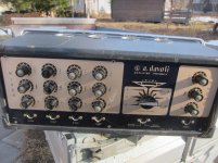
I just bought a very special preamp hand-made by one person, Emmanuel Go (of First Sound). I thought the community would find this preamp and photos of it to be of interest and the mods have graciously granted me permission to post some information and photos here (thanks Tony and mods).

First Sound is very much a labor of love of just one guy, Emmanuel Go, hand-building and crafting preamps one at a time for each customer. In this sense, it is very comparable to what Nelson does at First Watt.

The model is the First Sound Presence Deluxe 4.0 MkIII-SI, a 3-chassis unit w/ the Special Edition upgrade using Audio Cap copper capacitors.

These are essentially "bespoke" preamps, each one crafted and tuned specifically for the owner's system and system components. The design is a true dual-mono design, two preamps in one main control chassis with the PS transformer and PS capacitors housed in an external chassis to maximize performance while minimizing the impact of noise and vibration on the main circuit. Additionally, there are two chassis in one, with an inner chassis comprised of copper-plated steel to function as a Faraday cage to further reduce the impact of external noise.

Special care is also provided to provide vibration-damping and even the fasteners were selected based on comprehensive, long-term, listening tests.
Notable are hand-assembled volume controls, utilizing individual exceptionally high-quality metal film resistors at each gain position and a massive power supply, exceeding the power supply capacitance and "stiffness" of many high-end power amplifiers.

Dual Mono Construction using Copper Plated Steel Chassis
• Step Attenuators, Ladder Type using individual resistors (see below), designated as LTH 92
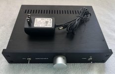
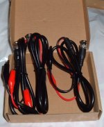
• SPS 2.0 External Power Supply w/ detachable umbilical cord

FS%20Presence%20Deluxe%204.0%20MkIII-Si.jpg


MkIII-S upgrade
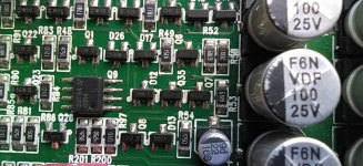
• MPDA (multi-phase differential array) developed by Shunyata Research. A sophisticated and innovative proprietary power line noise reduction filter array. Uses advanced 30 element surface mount components that significantly reduce power line noise.
• PSDS (power supply delivery system) An advanced system utilized for the power supplies..
• Upgraded main circuit boards
• Upgraded power supply circuits boards
• Additional 500 extra steps in the craftsmanship of this upgrade
MKIII-SI Upgrade
• As above with the addition of proprietary component filters that isolate electrical noise.
Paramount Special Edition upgrade
As the Presence Deluxe MKIII-SI with the addition of:
• LTV 92 Step Attenuators, Ladder Type attenuators using naked Holco Resistors
• Upgraded (Stage 3) Capacitors using AudioCap copper capacitors
• Expanded power supply capacitors
• Special Edition grounding topology
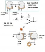
Volume attenuator
firstsoundattenuators.jpg


Copper chassis
firstsoundcage.jpg


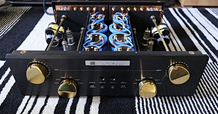
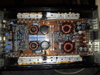
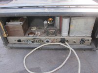
Here are some pics of the interior of the First Sound.

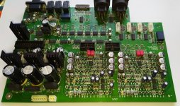
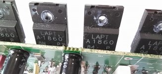
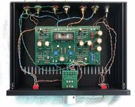
Top view without the covers; there are only two tubes, a 6DJ8 and OA tube per channel. The preamp is a true dual-mono design; two mono preamps mounted in a single chassis.

FS%20Preamp%20Top%20View.jpg


FS%20Preamp%20wo%20Cover%201.jpg


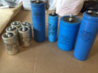
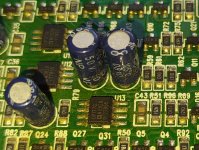
Just some, but not all of the power supply capacitance...and yes, that blue and brown wire is Shunyata Research OFE wire connecting everything. Emmanuel Go and Caelin Gabriel of Shunyata collaborated on incorporating several Shunyata technologies into First Sound preamps. The 6DJ8 triodes can also be seen in this photo. These tubes are super-durable, with mean life over 100,000 hours.

FS%20Interior%204.jpg


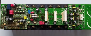
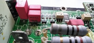
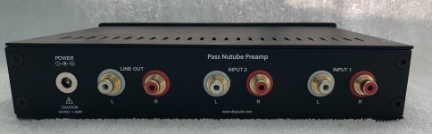
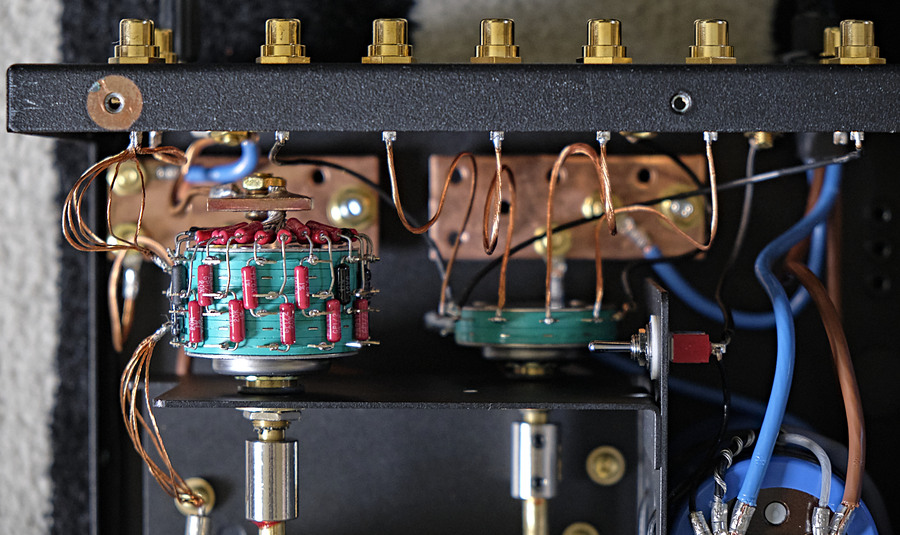
The back panel shows input jacks, wiring and huge copper bus bars for making and grounding connections. Note that there is no ground wire for each RCA jack, only a single + connection. There is also no insulation on the wires so as to not have any dielectric effect from various insulation materials; the dielectric in this case is air. The entire copper bus bar serves a ground for all inputs. There is also a switch (little red box) for each channel that lets me float the ground in the advent of any ground hum (there isn't; this preamp is DEAD QUIET).
FS%20Back%20Panel.jpg


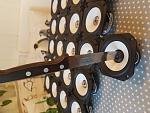
A close-up of the volume attenuator with individual metal film resistors.
FS%20Attenuator.jpg


There are also large, heavy, copper bus bars for chassis-grounding.
FS%20Ground%20Bus%20Bars.jpg


AudioCap copper capacitors.
FS%20Interior%202.jpg

FS%20Interior%203.jpg


Welcome the gang's questions...

Diode physics

Hi guys, a physics question for you. I was looking for a diode with a very low dynamic impedance. This is the delta-V forward drop resulting from a delta-I forward current.

Then I wondered: Is the diode forward voltage drop versus forward current purely physics determined or are there also manufacturing factors involved? In other words, is my search futile because all diodes are the same in this respect?

Jan

Threshold Adjusting Bias Touched Ground

So I was adjusting my bias today and apparently I had shaky hands. The temps were around 44c and I wanted to bring them up to 50-52 which I did.

In the process of measuring, I touched the bottom lead of one of the resisters to a ground contact which made a nice spark. I have to say, it was a high quality spark. I used to weld so I was impressed. Part of the ground pad under a nut is MIA though.

After adjusting the bias and almost lighting the house on fire the amp sounds really nice!! It is amazing how durable these things are.

Should I have any concern now that I have done this?

This brings me to the DIY portion of this post. I meguivered these fancy screw drivers because the bias pots are hard to access. After some more research and development I realized that I should add an electrical insulator so I shrinkwrapped my creation.


The steel is very hard and brittle so I heated it until it was red hot with a torch and hammered the tip to a 90 degree angle with my hammer. I then ground the tip with my bench grinder to form a flat head screw driver tip. I may make some more at other angles. Took all of 10 minutes to do both. I may make some more.

I didn't know if anyone has made screw drivers like this for adjusting bias on these S series amps so I wanted to share.

Using sound absorption to reduce standing waves

This subject has been talked about for a long time, but is still not well understood by even experienced speaker builders. What exactly goes on inside a cabinet is part of the art of speaker design.

One aspect is cavity resonances. These are different from panel or material resonances and are related to the size and shape of the internal air space of the cabinet.

The bottom line is that cavity resonances (which is what standing waves are) are generally not good unless they being used to generate extra bass.

One way to get rid of standing waves is to stuff the speaker. I have never liked the sound of a "stuffed" speaker. I believe what I am hearing is the sound reflecting back from the wall of stuffing due to an impedance change. Also the stuffing selectively absorbs some frequencies over others.

What's better is to put a sound absorbing structure in the center of the cabinet. I did this on a recent build and was pleased with the results. What this is is essentially a sound absorbing burrito. Its poly batting with fiberglass in the middle. Then its rolled up like a burrito and stapled together. It then sits in the middle of the cabinet behind the drivers. It sits between several braces and is also held in place by string so it won't move.

I noticed a very clean sound from using it. I don't think it significantly affects cabinet volume either.

Also here is an excellent tool for calculating standing waves of a typical square shaped cabinet

HiFi Loudspeaker Design

Attachments

  • IMG_0185.jpg
    IMG_0185.jpg
    952.9 KB · Views: 1,160

SUT polarity?

This is a very basic question: I have bought a pair of Sowter SUTs and I am about to wire them into my cart to amplifier path.

The Sowter site simply says to connect the white and yellow leads to the cart and the pink and mauve ones to the amplifier, without mentioning which lead matches which and which goes to the signal vs. ground path.

I guess I can find the in/out matching by tetsing which wires are connected, but how about the ground/signal? Does it matter at all?

Thanks.
gm

Sa9023 doesn't work with es9018k2m

Hi all,
I made a es9018k2m dac board and it works fine with diyinhk cm6631 board but it doesn't work with my sa9023 usb board, this one work fine with es9023/pcm5102 but when connect to es9018k2m there is no sound, i'm pretty sure i connect it the right way: 3 line LRCLK, BCK, DATA. I think i need to change some configuration setting to make it work with es9018k2m dac? Does anyone have experience with this?
Thanks!

Lobing in MTM with TPL-150H and 8PE21

I'm developing a 4-way digitally active system with powered subs, 2x 10" per side for midbass, 8PE21 mids, and TPL-150H as tweeter. Class D to drives the midbass and the goal is to drive the midrange with a 2A3 and the tweeter with another 2A3.

Calculations suggest the midrange and 2A3 will be the constraint in power-sensitivity and hence dynamic range. The 8PE21 is rated 98dB sensitivity, and naturally a second one would take it to 101dB providing a much safer starting point. This would be great if it didn't have a sonic cost, which is what I want to explore.

I'm aware in his initial work Joe D'Appolito postulated center-to-center distance in an MTM had to be one wavelength a the crossover frequency, and that he later relaxed this constrain in light of wavefront integration with "enough distance". Calculators predict significant lobbing, but assume the tweeter to be a point source. However the TPL is anything but a point! 😀

I approach this knowing it's likely not to work well, but want to experiment. I'm aware of commercial speakers getting good reviews and using 8" mids in MTM with a similar tweeter and 1.6kHz frequency (e.g.; Goebel Majestic), so I'm intrigued. Worst case, I'll build a TM section with same drivers. I built the attached as open baffle to run the experiment only.

Some constrains:
- I listen at 6 feet away from front baffles.
- xo frequency should be somewhere between 1.2 and 1.8kHz.
- I can only measure indoors.

How should I experiment, measure this???
If I were developing a TM I would measure each driver at 4", so to minimize room reflections, integrate both. But here I need to allow for wavefront integration from mids and tweeter. Should I measure at 6 feet away, at different heights to capture lobbing effects? Of course the room effects would then sneak in.
What do you recommend?

Thank you!

Attachments

  • 20200606_213439.jpg
    20200606_213439.jpg
    315.7 KB · Views: 757

How does the Krell S300i sounds so good such crappy components??

I feel this is a strange beast. Its a made in China amp. The internal components esp. the capacitor sucks (crappy brand). Then many folks here blasted the OP177 and it should not be in the signal path.


But reviews everywhere (including user reviews) says its good. Even better than tha 400XI. This is why I am really curious what makes it good?? Just doesn't make sense to me,


Btw, I have created a new thread. Decide to open up my S300i for cleaning and perhaps see what I can do to it!! Lol!! But as you can see, the amp has been repaired before. Perhaps as they said, its not the durable. Those resistors are hot when amp is working. Very hot. I guess some were fried.


https://www.diyaudio.com/forums/solid-state/357208-krell-s300i-teardown-improve.html#post6272930

Using Soundeasy files in PCD and Mic calibration help

I took measurements in Soundeasy and went through the post processing of combining woofer responses and tweeter but have not yet had the chance to work the crossovers in Soundeasy and I will be travelling. I am nervous about bringing my Rockey so I would like to play around with the measurements in PCD. Does anyone know how to export the combined woofer responses (the tweeter response is less of an issue as it is unchanged) so that I can use it in PCD? It gets saved in the driver file but it seems to be saved as separate measurements that the program comes back and combines the way I told it to. Perhaps I am just too new with Soundeasy but everything else so far has gone smoothly.


I would also like to calibrate an uncalibrated mic with my calibrated one. I have measurements for both and after finding inconsistency in the nearfield but consistency in the farfield, I will likely build the chamber recommended at the ARTA site. Can anyone describe what software to use and how to find the difference between the two measurements and then combine this with the Calibration file from my calibrated mic?


Thanks,

Jay

Damping Factor and different types of speakers

I wonder about DF importance for different types and kinds of speakers.
For example I am sure that Electrostatics "don't care" about DF at all as they do not generate any BACK EMF. Planar magnetics almost the same, as they have almost pure resistive impedance and do not generate BACK EMF either, or almost none.
Conventional dynamic speakers do generate BACK EMF and the overall damping of such speakers consists of their mechanical damping ability plus the electrical DF.
It is obvious that for different dynamic speakers their ability to perform damping as a result of electrical damping is different for each and electrical DF does not contribute the same given the same amp DF.
It is a pity that speaker manufacturers do not publish a figure that is the ratio between the mechanical damping and the electrical damping (say for a theoretical infinite amp DF i.e. zero output impedance) Such a ratio of mechanical VS electrical DF effect for a given speaker would have given us a good insight of how much DF is really important for a particular speaker.

Buzzing changes with volume pot position...

Well, I built a tube amp and everything is absolutely perfect with it, except that there is a a buzzing sound when the volume pot is anywhere but max volume, at max volume there is no buzz (or hardly any at all) but as I move the volume lower the buzz steadily increases, and it is very lound at minimum volume. I'm gathering that htis is a grounding problem, I've got a star ground, and I'm not sure what else to try. The fact that it changes with the volume control (which is right at the input to the circuit) baffles me as to why this is happening, any help would GREATLY be apreciated.

Bluetooth audio player

Hi guys,
I'm trying to build a bluetooth audio player and I need help on which hardwares should I use. I need to play audio via bluetooth receiver and I want to interface a 16x2 lcd screen to show the song details, volume control, etc. Can I use Arduino uno for this purpose? I have a 100Wx2 amplifier. I have no idea where to start. Please help me. And thank you in advance.

Harmornic Distortion

I found a graph on the attached from the old magazine. It is a measurement of harmonic distortion.

Does anyone know how to interpret it? How important does the measurement of harmonic distortion?

I see many sources nowadays don't have it. Also, I have loudspeaker building cookbooks. They didn't discuss how to measure harmonic distortion as well.

Anyone, please help to suggest to me how to measure it.

Thank you in advance

Attachments

  • distortion.png
    distortion.png
    110.8 KB · Views: 313

Dayton Audio SPA1000 1000W Subwoofer Plate Amplifier - x4

Up for sale is four Dayton Audio SPA1000 1000W Subwoofer Plate Amplifiers, I am selling due to them being not suitable for my build.

They have been used a couple of times but that's it so basically brand new, tiny marks from where the screw heads have contacted the plate but these will not be visible when you mount the amp as the screw heads cover them.

Small traces of glue & insulation are on the internal cover but this is not an issue as it is only cosmetic & will be on the inside of your cabinet.

I do not have the original packaging.

Would like to sell all four at once but I am prepared to sell them separately, collection would be preferred due to their weight but I can ship them if required.

All come with a power cable & fixing screws.

Postage to the UK mainland via DPD next day delivery is £30. This is fully insured hence the price.

£300 each excluding P&P

Located in UK, Nottingham
pfwZznZ

Attachments

  • IMG_3203.jpg
    IMG_3203.jpg
    298.4 KB · Views: 455
  • s-1600.jpg
    s-1600.jpg
    426.4 KB · Views: 116
  • s-l1600.jpg
    s-l1600.jpg
    445.6 KB · Views: 104

Stetsom Amps - Hacked PIC - Experiment

Hello everybody.
I opened this thread for illustrative purposes only.
I managed to do something that I want to share with this community.
I have a Stetsom 3k3es amplifier that has suffered significant damage both in power and audio, also damaging the primary IC (PIC16xxxx).
Unfortunately, it was impossible to find this IC without making too much effort (the manufacturer was not very helpful).
Since without that component, the amplifier would never have worked, so I should have thrown it in the trash, I decided to experiment.
I generated everything I needed, everything the IC does.
I made a separate external power supply to operate the power supply and an external oscillator to generate the carrier for the audio.
Now the protection systems do not work, but with a little effort they can be realized without problems.
I realize that it is unnecessarily complicated and that a new IC would have solved all the problems in one fell swoop, but in extreme evils, extreme remedies, it was a fantastic experiment that I didn't think I would complete and I learned many new things about these Brazilian amplifiers.
thanks to those who want to follow me.


YouTube

Bassworx BA1200.1d distorted output

I picked up this amp for 30 bucks knowing it wasn't working properly. I powered it from my car battery and it powered up fine so I connected a subwoofer and audio in and no sound. I opened up the amp and noticed a burnt trace on the bottom side of the board. I repaired the trace and tried it again. I'm getting mild bass out of it but also a scratchy distorted sound. I'm lost at this point,any suggestions?

Attachments

  • 20200701_233037.jpg
    20200701_233037.jpg
    1.1 MB · Views: 110

What about digital RIAA?

Hi all.
I just ask myself why there is no standard high quality digital RIAA diy boards out there.
I think a simple 24/96 ADC paired with an i2s USB input, a software like jRiver and an USB DAC are enough.
What i missed?
My goal is to play vinyl in real time through PC and DAC I still use every day with my liquid files.
Of course a buffer/gain stage is needed to match gain and impedance of turntable.
I speak about digital RIAA via jRiver.

Thiele TL806 Cab

Wanted to share my cab build. Almost finished I think, might add a grill. I started it years ago but got discouraged by some poor carpentry and shelved it. Picked it up last weekend and did some reshaping and routing... it looked good so I did the spray painting and ordered parts/Tolex to complete it.

Attachments

  • DC5EC1C6-891D-479B-B1D2-735E5C82CCDB.jpeg
    DC5EC1C6-891D-479B-B1D2-735E5C82CCDB.jpeg
    240.8 KB · Views: 109
  • 3695AD3A-EA5E-4CC8-9F1A-CEAEDEB36DD1.jpeg
    3695AD3A-EA5E-4CC8-9F1A-CEAEDEB36DD1.jpeg
    203.2 KB · Views: 99
  • 952DE109-55CE-47FC-9165-1A02D7C44CC2.jpeg
    952DE109-55CE-47FC-9165-1A02D7C44CC2.jpeg
    208 KB · Views: 100
  • 75A4DDC5-D2E6-4ED4-9E9C-FEAE4BB0EE5D.jpeg
    75A4DDC5-D2E6-4ED4-9E9C-FEAE4BB0EE5D.jpeg
    203.4 KB · Views: 89
  • 2AB3EB69-2776-49E0-A454-6D6C22E011A6.jpeg
    2AB3EB69-2776-49E0-A454-6D6C22E011A6.jpeg
    251.5 KB · Views: 89

What can I use to replace my KX DRIVERS & Audigy 2 PCI sound card that uses PCIE port

What can I use to replace my KX DRIVERS & Audigy 2 PCI sound card that uses PCIE port

I need some thing to replace my Audigy 2 card with kx drivers
I use kx drivers EQ and cross-over features.

Modern motherboards don't have PCI ports anymore 😱

So I need a PCIE card and drivers that have these functions

I just use fullrange 3 inch drivers and subwoofer on my computer, but it's still nice to have an EQ and cross-over function for subwoofer and the fullrange drivers too.

ac2ated = future?

I would be interested to see more investment in this type of technology for small homes too.

Continental and Sennheiser Developed New Sound Actuator Solution for Vehicle Audio | audioXpress

One of the key technology demonstrations in automotive audio at CES 2020 was promoted by Continental and audio specialist Sennheiser. The two German companies presented a "speakerless" audio system for the vehicle interior, which Sennheiser claims is able to generate immersive audio by exciting surfaces inside the vehicle to produce sound.

The ultimate 300B

The ULTIMATE 300B

Well, I know that the name is somewhat pretentious... No importance.

I have chosen this name just because it is the last version of my serie of prototypes that I experimented with VT25/10Y, 50, 2A3 and ultimately 300B. It was on Feb. 6th. 2008... But the final model is now on construction... Since a few days...

This amplifier is built in 2 monaural identical "mono blocks" that I wanted to built as compact as possible : 275mm x 175mm x 65mm for the chassis, with a vintage electronic instrument look.

It has a bi-power switching : LO 4Wrms / HI 8Wrms nominal power.

Here are the performances measured on the 2008 prototype :

THD for 1KHz Sinus @ 8ohm resistive load, no NFB :
HI 10W = 5.32% (at the threshold of clipping)
HI 8W = 3.75% (at the nominal power)
HI 4W = 1.69%
HI 1W = 0.7%
LO 5W = 4.96% (at the threshold of clipping)
LO 4W = 3.50% (at the nominal power)
LO 1W = 0.85%

Bandwith @-3dB/8Wrms = 8Hz-25khz

The 2008 prototype, still alive of course :
An externally hosted image should be here but it was not working when we last tested it.

An externally hosted image should be here but it was not working when we last tested it.


Tracing the chassis :
An externally hosted image should be here but it was not working when we last tested it.


Starting the drilling :
An externally hosted image should be here but it was not working when we last tested it.


Drilling completed :
An externally hosted image should be here but it was not working when we last tested it.

An externally hosted image should be here but it was not working when we last tested it.


Wait and see...

A+!

Help withTU 8200R

Please help . . . I'm stuck!

Assembling the 8200R, and I have run into some difficulty . . .

• Unit 1, side A. Am unable to find the location for R70. I have the resistor, but no place to put it.

• I have discovered that my circuit board Unit 1, side A has TWO positions marked as R64. One in the upper right hand corner, close to D6. The other is in the upper left hand corner, adjacent to Q4.

Any help with these two questions will be GREATLY appreciated!
Thanks in advance!

Chuck

Balance/Blender circuit instead of 3 way switch

Hi all! I am thinking of using a blender circuit instead of a 3 way switch for a Telecaster with 2 passive coils. I know the usual "Blender" circuit will not suffice. I have a dual gang center detent 500K pot. I want the following gains at these pot positions:


Gain% Neck/Bridge Pot position
0% N / 100% B (0 position)
100% N / 100% B (5 position)
100% N / 0% B (10 position)


Is this doable without adding a large circuit and battery? Would the circuit that I have attached work?


Thanks for any help

Attachments

  • blender circuit.jpg
    blender circuit.jpg
    59.8 KB · Views: 197

NRG Control PA-1 Preamplifier

I have this preamp on my bench for repair. Without a schematic or users manual I am helplessly floundering around looking for some indication of what is wrong. It appears the mute function is constantly turned on and consequently I get nothing out of either channel under any circumstance.

Internal inspection showed signs that someone had been there before me so who knows. Impressive internals and box. There must be 100 ss relays in this thing. The input relays seem to function properly since it properly selects the input channel and the signal makes it to the main board and then to what I suspect are volume control attenuators. These are labeled as mercury wetted relays. The signal never makes it out of these boards on either channel.

I have read some high praise of this preamp and would really like to hear it in my system and be able to please a hopeful customer at the same time.

Does anyone have experience with this preamp?

A schematic would be an incredible advantage and greatly appreciated if anybody has one. Operating instructions might help as well.

120 uF, 750 Vdc BIG Film Capacitors

"That's not a big film cap, THIS is a big film cap" /Crocodile Dundee

Arcotronics MKP 1.44/3
120 uF 5%
Un = 750Vdc
Urms = 440Vac

Body dimensions 7.75" by 3.25", plus threaded studs for ring terminals, and an axial mounting stud on the tail end.

I had dreams of building a big electrolytic-free tube amp; realistically, that's not gonna happen. The surplus place had 'em listed as parts for a big industrial UPS. (obligatory warning: Big capacitors hold enough angry pixies to kill you dead. act accordingly)

I have qty. 4. Asking $50 each, or take all 4 for $150 and I'll pay shipping. Venmo or Paypal, CONUS ship.


An externally hosted image should be here but it was not working when we last tested it.

Any info about this old PA/guitar amp?

Got another project, a A.Davoli 8092 K (very different from the newer 40W 8092 KB model) but can't find much about this.

I do get this is a mono push pull with EL34 output tubes from 1965

Can anyone see from the schematic if this is a Class A or AB?
And how much output power?

It also have a strange impedance selector, with connector is 0? Is is ground?

Is phono (Fono in schematic) a line in or a RIAA stage?

It is missing some fuseholders and the magic eye so i can't measure plate voltage yet.

Attachments

  • a.davoli 8092k.jpg
    a.davoli 8092k.jpg
    197.1 KB · Views: 151
  • 2a.davoli 8092k.jpg
    2a.davoli 8092k.jpg
    227.1 KB · Views: 139
  • 3a.davoli 8092k.jpg
    3a.davoli 8092k.jpg
    222.9 KB · Views: 157

Help withTU 8200R

Please help . . . I'm stuck!

Assembling the 8200R, and I have run into some difficulty . . .

• Unit 1, side A. Am unable to find the location for R70. I have the resistor, but no place to put it.

• I have discovered that my circuit board Unit 1, side A has TWO positions marked as R64. One in the upper right hand corner, close to D6. The other is in the upper left hand corner, adjacent to Q4.

Any help with these two questions will be GREATLY appreciated!
Thanks in advance!

Chuck

Driverack 260 filter issue

Driverack 260 seems to completetly mess with the phase if the high pass filter is disabled. What do you expect when you change the characteristic of a high pass filter that is set to "OUT"? I expect no effect on phase and magnitude. Next post is 2 photos, taken with exactly the same setup, input signal YELLOW (10Hz), trigger on input signal, output 3 signal in PURPLE,
First pic is output 3 HPF set to "OUT" and "BS6", 2nd photo exactly same with output 3 HPF set to "OUT" and BS12".


What is your opinion?

Bass reflex not so good

Hi everyone.
I would like to ask for help with the sound of a bass reflex.
There is something that does not convince me and many other people, there seems to be something "dirty" in the system response.
I believe there is some resonance, and I would like to ask you for help in identifying and I hope to solve the problem.
The bass is inserted in a 3-way system, is used up to about 500Hz and has 2 woofers.
The speakers used are 416-8B GPA and the cabinet, as you can see from the picture, I think I am right in saying that it is very hard.
The front is 40mm (beech) and the rest 30mm (birch)
the interior was filled with polyester fiber, obviously without saturating the internal volume.
Also you can see from the impedance curve, currently the system is tuned to 35hz.
We made a 25hz attempt, the overall response improved, but the "confusion" in the sound is there.
Thanks a lot for any help you can give me.​

Attachments

  • double416-8B.png
    double416-8B.png
    65.9 KB · Views: 672
  • cabinet.pdf
    cabinet.pdf
    148 KB · Views: 172

Old graph of EV 15 inch fullrange in a factory RJ emclosure

60's EV SP15 with "mystery" control. (not a coax) There's only about 2 cubic foot volume. This made my AN10 in 70 liter reflex sound pathetic with Stanley Clarke giving an upright bass some workout.

The measurement was in-room with the cabinet in an 8x10 room with doorway to hall adjacent to the left of the cabinet.

FWIW I think its an idea worth pursuing and would try the JBL lens shape vs others.

w4kNDnv.gif

j3ElbpJ.jpg


Here's a pair of SP15 https://img.canuckaudiomart.com/upl...-ev_electrovoice_sp15_15_coaxial_speakers.jpg

Schematics

Hello all - does anyone out there have schematics for Demeter (VTMP 2) or Summitt (MPC 100) units. Contacted both companies but either they no longer have copies (Demeter) or can’t supply due to restrictions (Summitt). These are both units bought and owned by me and used (till they broke) for many years. Any help is very much appreciated - just want to be able to fix what I own. Cheers!!
Projects by fanatics, for fanatics
Get answers and advice for everyone wanting to learn the art of audio.
Join the Community
507,768
Members
7,887,665
Messages

Filter

Forum Statistics

Threads
406,191
Messages
7,887,665
Members
507,768
Latest member
Bhobski