Hi, letting a woofer run full range and using a high pass filter for the tweeter is as minimalist as it gets. I understand there are pros and cons but being new in speaker building doing a 2-way similar to the Seas A26 kit in Madisound appeals to me.
As you can see in the kit's schematic the resistor is in series w/ tweeter. I thought RC filters had the resistor parallel to load (tweeter) so am I wrong and this schematic correct?
As you can see in the kit's schematic the resistor is in series w/ tweeter. I thought RC filters had the resistor parallel to load (tweeter) so am I wrong and this schematic correct?
Attachments

It is not an RC filter in the conventional sense. It may help to consider it as a capacitor to filter out the lows, and which is working with this load.
If you use a resistor in parallel you will need a larger capacitor, and the resistor will reduce the tweeter impedance variations but the impedance in the passband will be lower.
If you use a resistor in series you will need a smaller capacitor, and the resistor will reduce the level of signal at the tweeter but it will be subject to the impedance variations.
You can use both at once.
Just an afterthought AllenB. I can calculate capacitance using desired cutoff frequency and tweeter impedance and do away with resistor altogether right? Isn't this the approach used by Reference 3A?
Thanks sonusanti, since the Reference 3A uses a resistor, add the tweeter impedance and the resistor together and use the frequency to get the capacitance.
FYI AllenB. Here's an excerpt from Soundstage! HiFi's review of Reference 3A's MM de Capo BE:
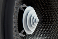
"As I recall, the original MM had a carbon-fiber midrange-woofer, as does the new one, but this model’s cone looks a little different: at its center, in lieu of a dustcap, is an oddly shaped white object called a Surreal Acoustic Driver Lens. According to 3A, this “is used to prevent formation of air vortex’s generated by condensed air particles and turbulence in the deep center of loudspeaker driver cones. Inherent noise caused by this vortex is drastically reduced and is effectively diffused by the lens.” Interesting -- I’d never seen such a thing before. As always, no crossover is applied to the midrange-woofer, and only a single capacitor is used to roll off the tweeter’s low end."
"As I recall, the original MM had a carbon-fiber midrange-woofer, as does the new one, but this model’s cone looks a little different: at its center, in lieu of a dustcap, is an oddly shaped white object called a Surreal Acoustic Driver Lens. According to 3A, this “is used to prevent formation of air vortex’s generated by condensed air particles and turbulence in the deep center of loudspeaker driver cones. Inherent noise caused by this vortex is drastically reduced and is effectively diffused by the lens.” Interesting -- I’d never seen such a thing before. As always, no crossover is applied to the midrange-woofer, and only a single capacitor is used to roll off the tweeter’s low end."
This is a high pass RC filter. The "resistor to ground" is the series resistor plus the tweeter impedance.
The series resistor is sized to attenuate the tweeter to match the woofer, and then the capacitor
is sized to set the roll off for the sum of the series and tweeter resistances.
The series resistor is sized to attenuate the tweeter to match the woofer, and then the capacitor
is sized to set the roll off for the sum of the series and tweeter resistances.
Thanks @rayma. That much is clear to me now. I am of the belief, however, that the ideal 2-way crossover should only have a single capacitor i.e. it uses the tweeter itself as the "resistor to ground" as was done in MM de Capo. This, of course, requires much more care in driver selection for DIYers apart from other considerations. Cheers.
This blog post should answer your question:
A Speaker Maker's Journey: Crossover Basics - Driver Response
A Speaker Maker's Journey: Crossover Basics - Driver Response
Personally I would not try to emulate the de Capo's crossover design, given what it produces:
SoundStageNetwork.com | SoundStage.com - NRC Measurements: Reference 3A MM de Capo BE
If this is the result of 'carefully selected drivers' to suit this crossover topology, I'd hate to see it tried with less perfectly chosen drivers. I suspect the Seas kit from madisound performs better in most if not all areas as well, given it sticks closer to the tried and true 'use well behaved drivers with gentle roll-offs and no big resonances' formula for this type of design.
This lens suggests an attempt to control the breakup region. I have not seen a demonstration. It claims to improve directivity. Then again it claims to be an aerodynamic improvement, not sure whether that is what I require in a cone.
Either way, using an electrical filter also deals with the breakup region and can do so effectively.
So I have to ask, what is the problem with resistance. Your tweeter already has a few ohms of resistance in series (the DCR of the driver).
Either way, using an electrical filter also deals with the breakup region and can do so effectively.
So I have to ask, what is the problem with resistance. Your tweeter already has a few ohms of resistance in series (the DCR of the driver).
Attachments
Thanks guys. You've given me good ideas and arguments.
Designers take various paths as we all know. It just happens that the minimalist design philosophy appeals to me most. The less is more credo.
In this crossover subject I notice that the components are there to "cure" driver characteristics and imperfections. In MM de Capo's case I think they were bold enough to be minimalist because they have full control on driver production. This is why DIYers like us are more wary because we don't have that control.
I'm willing however to try and see if it works. On resistors I have nothing against them at all. Its just that if I can get the cutoff frequency I think I need using tweeter impedance as R to calculate C then why put an extra R there? The calculator gave 12uF as C needed to get 2200Hz at tweeter's 6ohm so there.
I could be insanely naive but in this hobby making mistakes is our best teacher. Keep well guys. Let you know when I get there.
That is one good reason @PeteMcK thank you. There is a 3dB difference in the sensitivities of drivers I'm using. I'm playing this by ear, literally, my final arbiter. I want to hear how that difference will sound like and take it from there. Once I complete this project I'll update you guys.
As I said if you have full control over production of drivers like Reference 3A then going solo cap makes perfect sense to me. If not I'd still stick to first order 🙂. Thanks
As I said if you have full control over production of drivers like Reference 3A then going solo cap makes perfect sense to me. If not I'd still stick to first order 🙂. Thanks
'going solo cap makes perfect sense to me' - not to me, higher order on the tweeter crossover improves both power handling and phase alignment
In this crossover subject I notice that the components are there to "cure" driver characteristics and imperfections.
Wrong. Some (as in 'some', not 'all') equalisation circuits are there for that purpose. The majority of components are there to shape the acoustical and electrical responses to given curves, in order to achieve a given set of desired results.
There are as many solutions as there are designers. If speaker manufacturer maintains control over entire process from driver design, fabrication including enclosures as most of them do then using "less" components in your crossover is a testament to your driver's superiority and high precision. But that's just me of course. I agree to disagree.🙂
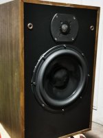
Hi everyone. Sorry this should have come first. I am pleased to report that my 2-way speaker project is finally a success after a month of planning and construction. As you know I tried to emulate Madisound's A26 kit but since I recently purchased a Thiel H1715 tweeter 92dB, a performer that exceeded my expectations, I had to go with it and find a partner.
I had previously ordered the A26 Mundorf crossover set so again I had to use these somehow even if I hadn't decided on the woofer. I chose the Morel MW266 89dB. So I used the 3.3uF in series with 10+8.2 ohms to get an effective R of 24.2 ohms for Fc of around 2KHz.
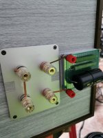
Used Supra externally and internally. The toughest part was attaching the crossover directly to the binding posts internally. They were outside initially and used a copper braid to connect it. This sounded bad. Suspected it and moved it inside getting rid of it. Also used my extra Supra cable as jumper on negative binding post. And then...finally the open, transparent, and the wide range I had hoped were all there. Not worried about power handling at all. This Morel can take 1000W short term.
Thank you for your ideas and support. For the biggest fans of sophisticated crossovers I wonder if you've ever heard solutions from Lowther, Fostex, AER, Audio Nirvana, etc. They're even more extreme than I am.
Cheers!!!
I had previously ordered the A26 Mundorf crossover set so again I had to use these somehow even if I hadn't decided on the woofer. I chose the Morel MW266 89dB. So I used the 3.3uF in series with 10+8.2 ohms to get an effective R of 24.2 ohms for Fc of around 2KHz.
Used Supra externally and internally. The toughest part was attaching the crossover directly to the binding posts internally. They were outside initially and used a copper braid to connect it. This sounded bad. Suspected it and moved it inside getting rid of it. Also used my extra Supra cable as jumper on negative binding post. And then...finally the open, transparent, and the wide range I had hoped were all there. Not worried about power handling at all. This Morel can take 1000W short term.
Thank you for your ideas and support. For the biggest fans of sophisticated crossovers I wonder if you've ever heard solutions from Lowther, Fostex, AER, Audio Nirvana, etc. They're even more extreme than I am.
Cheers!!!
Attachments
- Home
- Loudspeakers
- Multi-Way
- High pass filter question