Can you split xlr to rca into the MiniDSP

Is it possible to split the signal from the Behringer amp(6000) xlr to rca. Splitting the rca into two and connecting that to the output on the dsp?
Im not even sure you'd have full dsp on both lines separately correct?
How else do you run dsp on two speakers wired in series to an amp or is that only possible if they are connecting to their own separate inputs on the amp?
Ive been confused about this for a while and not sure ive found any good info online.

tda 1541, again

I know this has been done to death, and that's what I'm struggling with. there is so much information out there that I am finding it hard to decipher what's what. iv just spent the last 2 hours reading two threads and all it has done is give me a head ache. I would very much like to do a bit of modding with my cda94 but I cant see the woods for the trees at the moment. I can follow lines on a schematic and solder but as for designing a circuit or understanding how it all works is beyond me. I have been reading about different mods but a lot of the posts are just guys, with a lot better understanding than me, just chatting and bouncing ideas of each other.
can I be pointed in the direction of some well trodden paths to upgrade this chip, with specifics as to what to do. I have changed the opamps and done a nos mod so far. I have just been reading about a grundig dem mod but cant find a definitive set of instructions, maybe what I'm after is too basic for this forum.
any help would be greatly appreciated.

cheers adie

Inlet Power Switch Choice

Hello,

I am building a streaming amplifier with the following components:
Amp: LM3875 premium kit from Audiosector. Stereo, one rectifier. I believe his guide uses a 5A fuse.
Streamer: Raspberry Pi 3, IQ Audio DAC, 4" Waveshare screen all powered off of a MeanWell 15-5 PSU. I am not sure the total current draw, but I do not think it should be very high.

What type of inlet switch should I buy? I see all sorts: filtered, unfiltered, ones with the switch built into the unit, etc.

I live in Canada, any advice would be greatly appreciated!

3D Printed Drivers FD51 + WF81 2-way vs Industry Bookshelf

Hey everyone

Posting here as may suit this group more due to its lack of off the shelf drivers in use. In this video I use 2 of my own 3D printed drivers, and run them in a printed 2-way bookshelf cabinet and compare it to a entry level bookshelf speaker.

Aim of the video is to see where printed drivers and cabinets are when comparing then to industry ones, and what areas need improving.

YouTube

Paul 🙂

Chord SPM 900 chassis tickles

Hope y’all can help troubleshoot this issue in my trusty old Chord power amp. The SPM 900 was their first commercial production model.

Been using this amp almost daily generally without issue but recently noticed I was getting some power leakage to the chassis?

I feel this as a little tickle -an almost pleasant little buzz on your finger when you touch the amp but it is especially pronounced for example when you touch an input jack connected to my iPod.

Between the source and the Chord I am using a Akustyk passive preamp (basically a Khozmo stepped attenuator and input selector in a box).

Could be anywhere right?
Any likely candidates?
Where to start?

Thanks for looking

Independent ESP Power Supplies for Preamp (Analogue + Digital)

I made a little smoky smell with my ESP power supplies today, which did not make me happy.

I need a -5V / 0V / +5 power supply for my PGA2311 analogue side, and I also need an independent 0V / 5V power supply for the digital side.

I picked Rod Elliotts P05D for the analogue power supply, as it also gives me ~13V auxiliary unregulated output to drive my source selection servos. I used Rod's P05 Mini for the 5V digital power supply - but with only the positive side components fitted. It's a bit simpler.

Both power supplies operate from the same 9V AC input, sourced from a wall-wart transformer. (18VA). I would like to keep all the mains voltage out of the preamp box.

On the 5V Mini; AC is applied to AC1 and AC2, with no connection to the GND input terminal.
On the bipolar P05D, my single AC input is connected to terminals AC2 and GND.

Now perhaps may of you have already seen where this is going... but I didnt! My 0V outputs are different! With the same AC input, the 0V outputs differ by 5.85V which is a horror show. And although I can plainly see each PS has a different architecture, I don't know how to fix it. (The 0V analogue and digital 'ground' will ultimately be joined at one point on the PCB so this different is... unacceptable).

Should I build two bipolar supplies and just ignore one of the -5V outputs? I am willing to start from scratch, the only thing I really want to keep is my external 9V AC power supply. Please please please set me straight! What is the simplest architecture to get from one AC input to the independently regulated digital/analogue supplies that I described above?

Popchops.

Attachments

  • 20200801_141441.jpg
    20200801_141441.jpg
    635.5 KB · Views: 170

Need help from believers in horn HOMs

I found out that my HF206 is simply a HF146 with an adapter. That opens the door to some more options as i can use 1.4" entry horns/waveguides.

I am currently unhappy with my PH 2380, and I suspect that the diffraction slot is causing the problems. Even though it is tuned rather warm, it still sounds shrill and honky even at moderate volumes.

The XT1464 looks like a much smoother transition all the way from the driver to the baffle, but it still has quite a long throat. I am worried about audible high order modes.

As in many other areas in this hobby, people seem to be divided on the matter of HOMs. Some say they don't matter, I definitely believe that they do. I would really appreciate if someone with a good understanding of the HOM-issue in horns and waveguides could give me their opinion on the XT1464.

Using an Osccilloscope...

Several years ago, when I was still living at an apartment I was dropping off some trash and found someone was throwing out a nice analog 42W Weller soldering station and an Elenco 1525 35Mhz Oscilloscope, both of which I promptly grabbed. I love the soldering station, I use it all the time. But as far as the scope is concerned, I never used it and I confess, I have no idea how. I very familiar with using a traditional DMM, I use them all the time at work, but never an oscilloscope.

I have no idea how to use this thing, I'm familiar with a DMM having two leads, but this thing only came with one connected to the Yaxis input. Though I see that this lead has secondary to the probe tip, there is a separate collar connect to short removable lead with an alligator clip, with a three position switch on the side of the probe (1X, REF, 10X).

Would I be correct in assuming that is I wanted to look at the output of a 12vac power supply, would I connect the alligator clip to one side of the power of the output and touch the probe tip to the other? Or am I an the complete wrong track and I would be creating a direct short across the output?

Here is the scope and probe in question. Thanks for any help in advance.

Attachments

  • 20140101_115416.jpg
    20140101_115416.jpg
    882.4 KB · Views: 540
  • 20140101_121612.jpg
    20140101_121612.jpg
    658.5 KB · Views: 532

Project – 2 x Peerless XLS 10” 20Hz tuned slot port subwoofer

Hi all,

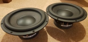
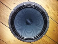
I have two Peerless 830452 drivers which I’m planning to put into a single slot ported enclosure. Picture of both drivers attached. I know I should be building two separate units to smooth out room modes but my partner would not accept this.

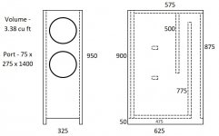
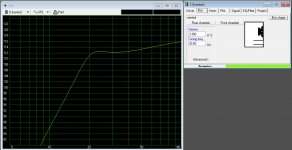
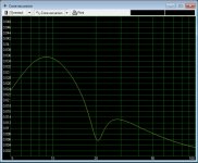
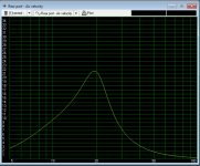
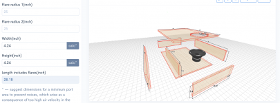
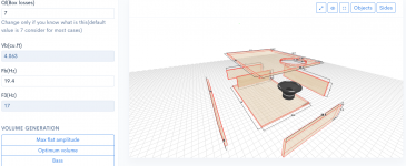
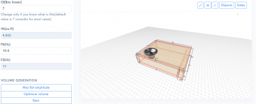
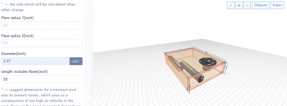
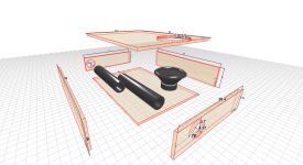
I know these drivers are best suited for either sealed enclosures or enclosures with passive radiators, but I’m going ported. One of the reasons passive radiators are desired to compliment this driver, is due to sealed configuration not achieving good LFE due to steep roll off, and the ported configuration requiring very long and large csa ports to achieve good LFE without excessive port noise. Size is not an issue for me, I am only limiting myself by attempting to use a single 1220x2440 (4ft x 8ft) MDF panel. So, I’m going with a 3.38 cubic foot enclosure, tuned to 20.6Hz with a slot port 11 x 3 x 55” long (27.5cm x 7.5cm x 140cm long), which limits port velocity to 21.5m/s @19.5Hz (≈6% SoS @ 343m/s) with 350W on each driver. This slot port has a csa equivalent to a single 6.5” diameter round port, which sounds very reasonable for two 10” drivers. Note: Peerless quote the XLS driver at 150Wrms, however, it’s well known these drivers can handle more, with majority of users running these at double their quoted rated power handling. 350W per driver pushes excursion to 13mm at ≈28Hz, peerless quote the xmax @12.5mm and I’ve seen reports the Xmech is around 20mm so no issues. Cabinet will be 1” MDF all round, with double thickness front baffle. I’ll round over the edges, and will attempt to paint for best finish I can possibly do (fair at best).

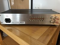
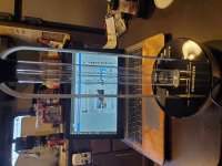
My current system consists of a digital source into a Denon AVR-1907 AV amp, currently powering two floor standing speakers in stereo.

Due to budget limitations, I have two options –

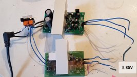
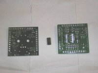
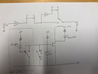
1. Buy a minidsp 2x4 HD and configure two AO in stereo for the existing floor standers, and two AO in mono for the subwoofer drivers, and feed all four as analogues into the AV amp (Front L, Front R, Surround L, Surround R) providing 120W per channel. Note: The Denon av amp has 7 analogue ins, which can be used where the audio is decoded outboard in a DVD player for example and 7 analogues come into the amp from the player. Using the amp and minidsp in this manner, I’ll have a better low pass filter, and will be able to configure a sub-sonic HPF. Although specification states 6-8 Ohm loads, I’ve found Denon techs online stating that 4 Ohm loads can be driven with their AV amps – worst case I trip on over-current protection at higher volume levels.

2. Buy a crown XLS 1002 drivecore series 2 and run with the built in LPF, but I’ll have no sub-sonic HPF. This would be connected to the AV amps sub-out. In this scenario, I’ll have to set limiters on the amp, which will be configured to not breach 20mm Xmech, which equates to 220W total (110W per driver). This is less power than if I were powering direct off the AV amp, so I don’t really gain from this option !


If I buy the amp, I’ll buy the minidsp next year, and visa versa, so next year I’ll have both. My preference is to go the minidsp route, since power will be approx. the same and I get to play with a very cool box of tricks !

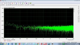
Winisd modelling attached for 350W per channel. Note: No HP or LP filters configured in the modelling, I have however put a second order high pass butterworth @ 8Hz to simulate the XLS natural roll off.

I’ll model it in Hornresp too when I get a chance.

Couple of questions:-
· Can someone kindly verify my design ?
· Any foreseeable issues ? anything I’ve overlooked ?
· Opinions on which option to go for, crown XLS or minidsp ?
· Anyone see a problem with me using the AV amp the way I’m planning ?


Any advice and answers would be appreciated !! Many thanks in advance, Martin

Peerless 830452 data sheet here – https://www.parts-express.com/pedocs/specs/264-1108--tymphany-xls-p830452-spec-sheet.pdf

Denon AVR-1907 manual here - http://www.google.co.uk/url?sa=t&rc...r-Manual.pdf&usg=AOvVaw39Kj6qKK6h3Jud7lutRdvk

Minidsp 2x4 HD manual here - https://www.minidsp.com/images/documents/miniDSP 2x4 HD User Manual.pdf

Crown XLS 2 drivecore manual here –
https://www.google.co.uk/url?sa=t&r...original.pdf&usg=AOvVaw0HgdqqGoTxTJKGz8SB-xZs

Attachments

  • Peerless XLS 1 - Driver pic.jpg
    Peerless XLS 1 - Driver pic.jpg
    699.5 KB · Views: 1,984
  • Peerless XLS 2 - Dims.JPG
    Peerless XLS 2 - Dims.JPG
    56 KB · Views: 1,644
  • Peerless XLS 3 - Winisd SPL.JPG
    Peerless XLS 3 - Winisd SPL.JPG
    153.9 KB · Views: 1,593
  • Peerless XLS 4 - Excursion.JPG
    Peerless XLS 4 - Excursion.JPG
    132.1 KB · Views: 1,533
  • Peerless XLS 5 - Winisd Velocity.JPG
    Peerless XLS 5 - Winisd Velocity.JPG
    149.7 KB · Views: 1,475

What does on center mean?

I am making a drawing to submit to DIY Audio Store to convert to CAD and having a slight hiccup with my speaker binding posts.


The description for the binding posts says "holes drilled 0.75" on center"
Does this mean that the distance from the center of both holes should be 0.75" apart? Or 0.75" in either direction from a midpoint spot?


Parts Express Dual Binding Post Banana Jack 1 Red 1 Black

Amp heatsink mounting question

Hi,

I have a retail amp unit that was shipped to me. It must have gone through a storm since all the mounting screws for the amp board/heatsink came off.
One of screw head broke off in the heatsink thread.

My question, the standoffs were of the nylon plastic type. Were these used to save on costs or to isolate the heatsinks from the chassis ground?

If I replace them with brass standoffs, that would connect the heatsinks to the chassis ground via the screw to some degree of contact between metals.

Is this ok? Do you see any issues with the heat sink as part of the chassis ground connected electrically?

solving equation for frequency

So I am trying to create a sine wave generator that puts out 440HZ at 1v. I came across this circuit but how would I solve for R1,R2,C1,C2 given the equation for frequency? If it were just one variable it would be simple but four variables is troubling me to say the least. I do not understand the relations enough to solve this. Thanks for any help.

Attachments

  • 681c1525b90461e550b8dc21e9c441ac.jpg
    681c1525b90461e550b8dc21e9c441ac.jpg
    29 KB · Views: 150
  • frequency.PNG
    frequency.PNG
    7.5 KB · Views: 165

Sewer Drain PVC for ports?

https://www.homedepot.com/p/JM-eagle-4-in-x-10-ft-PVC-D2729-Sewer-and-Drain-Pipe-1610/202280933

I usually use schedule 40 PVC for ports in BR boxes, but came across the above and wondered is there any reason not to use it instead? It is a bit cheaper for the pipe and the elbows I will need for a project, but also because the walls are thinner it will be lighter and take up less space in the box.
Is using port material with thinner walls not advised for some reason? Maybe more prone to unwanted vibration or resonance?
Thanks

Sony double deck capstan motor speed issue

Hi

I have recently restored two Sony Mini-Hifi combos.
(TC-H5900 Deck TCM-190R Mechanisms also used on other decks)
Cleaned Lubed & replaced the dreaded tape take up clutch cracked reel.
I fitted also new belts & pinch rollers.
The CD pick-up & belts were also replaced.
All functions work OK & sound is also fine.
On one of the deck units, on deck B when playing a cassette the motor starts faster say 5% but after a minute or so stabilizes to correct speed.
I managed to calibrate it with a 3KHz (Bought Online) calibrating tape when speed was stable, and have a time mismatch with same type of tapes between the decks of 15-20 seconds (C60 Type). Wow & Flutter was measured with WFGUI & was also OK.

The motor is 4 wire Type and is controlled by 2 transistors. One for On / Off & the other for H/L switching, according to the schematics.
I could switch the motors but I don't want to disassemble it one more time and I can live with it.

Has anyone faced the same issue before & found the culprit ?

Thank You for Your attention

Yamaha RX-V 2500 idle temp

Hi
I bought a used RX-V2500 and wanted the fan to be acrive sooner, before the amp becomes too hot, a few years ago I read an article of a guy who put in a resistor, that makes the fan coming in quicker, but I can not find the link any more, if you give it in in Google search, you are being directed to a weird website, nothing to do with this article, has anyone saved it by chance?
Thanks for any info on that.
Tojoko.

ELEKTR⚡A is a true High-Voltage lab supply, truly DIY-friendly

The Elektria concept first came to birth as an accessory in this project:

https://www.diyaudio.com/forums/tubes-valves/327831-supply-center-testing-tube-projects.html

I needed a low-power, variable supply to be used mainly as a bias source or for other secondary tasks.
As I found usual solutions unsatisfactory for various reasons, I brewed my own 0-100V regulator.
I came up with a Rush cascode as error amplifier, directly driving the ballast transistor.

This configuration offers lots of advantages: simplicity, no need to generate a tail current, capability to reach zero volt output easily, no need for auxiliary supplies and capability to regulate with less than 1V dropout.

I was so pleased with the concept that I decided to test it in a standalone instrument: a 0-500V, 0-200mA.
For this proof of concept, I deliberately pushed the envelope to the limits: for example, the supply regulates 500V using mostly 300V transistors.
Not something I particularly recommend, but it demonstrates that it can be done.
The sensible solution would be to add cascodes of course.

Elektria is robust, stable and well-behaved, and its performances are good, but it cannot match the stability and regulation of a conventional, opamp-based regulator.
However, the performances are sufficient for at least 99% of tube-related DIY, and it has all the basic features of a lab supply: voltage and current can be freely adjusted between 0 and the maximum, a LED indicates when the current limitation is active, and it is equipped with a standby switch.

It is remarkably cost-effective, and can be built for practically any combination of voltage and current with minimal adaptations.

Attachments

  • Elektria.png
    Elektria.png
    56.9 KB · Views: 3,096
  • Elektria1.jpg
    Elektria1.jpg
    412.8 KB · Views: 3,050

KSS-272A tracks well when tilted

I've acquired this CDP-X303ES piece of wonder and the sound shocked me to the core in a positive way...ODAC goes to the trash or maybe gets a second chance with a USB isolator, will see. 😀


Unfortunately, a few discs have a very audible stutter and its "rhythm" seems to match the laser lens movement. The lens is not moving up and down, but sideways - towards and away from the spindle (or maybe the opposite direction, it's very hard to tell). One disc is jittery throughout all songs, a few only in the end. Others are completely fine including all CD-Rs I threw at it.


I took off the metal laser lid that reveals the lens movement coils and it was surprisingly clean inside so I don't believe there's any dust between the laser sensor and the middle lens, more so because that cavity seems pretty closed off.


So, I lubricated the motor with sewing machine oil (both bearings) and the linear bearing (molybdenum disulfide grease) which didn't make any difference. Also fiddled with spindle height - found a spot where it stutters the least on that particular disc.


Then I took the mechanism apart, so I could better see what the laser is doing during playback and noticed that the playback improves significantly if I tilt it so that the gravity pulls the laser assembly away from the spindle (towards the last track of CD). The stutter transitions to jitter sound, then it becomes inaudible once I find the right angle. Same improvement if I gently push the laser assembly with my finger (keeping the mechanism flat) to mimic the gravity's effect. Once I return it to flat position, or release my finger, the stutter returns.


I can see that somebody has fiddled with TB and FB pots (not me, I promise) - the plastic has screwdriver marks. Thankfully, doesn't seem like they touched APC. TB has the strongest mutilation marks...


I attach an audio sample (1st song of the disc that's jittery throughout). It starts with the mechanism in flat position. On the 18th second I start to tilt it and play with it until the jitter almost disappears. On the 41st second I return the mechanism to the flat position, the sound cuts out for a while, then returns with the jitter.


I have a digital oscilloscope, multimeter and half a brain when it comes to fiddling with delicate mechanisms... So given these clues, what are your first thoughts?

Attachments

  • test.mp4
    2.6 MB

USB sound card for noise measurements

Hi ! i would like to start some noise measurements on preamps i have at hand and i have been already advised to look for a low noise usb sound card more than a scope (i guess much more expensive by the way).
I intend to use a Windows 10 laptop and Arta software that i like. (Someone recommended me instead WaveSpectra ?)
I have some big questions:
- to measure the noise (usually tenths of mV) will i have to use the mic input on the soundcard and set the gain to maximum ?
- will the soundcard own noise have an impact on measurements ? unfortunately i cannot test them without buying them.
- which soundcard is famous for very low noise at a good price ? (i read good opinions about the EMU 0404 but it is too old, difficult to find and likely with drivers issues for using it with Windows 10)
- will using an external +5VDC well regulated power supply (i.e. instead of the laptop usb bus voltage) help in reducing usb sound card own noise ?
If there is a specific thread treating this topic please redirect me there and close this one of course.
I am attaching (i do not know if i did it right) the noise of my current usb sound card (Terratec Aureon USB 5.1) with the mic input open and powered from the laptop. (This laptop is running Win 7 but mine runs Win 10).
Thank you all indeed.
Kind regards, gino

Attachments

  • terratec aureon usb noise.JPG
    terratec aureon usb noise.JPG
    159.8 KB · Views: 589

Are bypass capacitors needed with transistor biasing circuit

Hi there, I have a circuit with a voltage divider that divides the supply voltage with 3 resistors. For biasing the bases of transistors, I've done this before to have a lower voltage bias for simple amplifiers, and higher voltage bias near vcc/2 for emitter followers.

I have always used them in op amp circuits, but not usually with transistor circuits.

Should I be using them in BJT circuits like emitter followers and amplifiers? Please see the attached figure.

If so, is this attachment I have included the right or best method? I can think of several different arrangements. Like walking them down the resistor divider from resistor to resistor or hooking all capacitors to ground. Also, are the capacitors shown connected to vcc 9v needed? Sometimes I see these caps omitted.

I know the size of the capacitors in the schematic should be increased, but is the circuit arrangement correct?

Thank you very much for helping.

Attachments

  • BiasingQuestion.PNG
    BiasingQuestion.PNG
    108.9 KB · Views: 209

Troubleshooting Unexpectedly Steep Drop Off on Low End

I designed a speaker using WinISD to have a -3db @ 21.5 hz and -10db at 17.2 Hz. However when I actually measure the speaker I get a much steeper drop off. Between 37 and 23 hertz the real sub-woofer drops 15 db whereas the simulated sub-woofer falls only 2.5db.

The simulation was done with the measured T/S parameters of the driver after break in. The port length is correct to within a couple millimetres. The box volume takes into account the speaker, port and bracing displacement. The air velocity in the port is 2% of the speed of sound at this volume so I dont think there is any port compression. I have tried varying Ql, the leakage loss, in simulation but it does not have a dramatic effect that would explain the discrepancy.

This is my first speaker build, so I am really at a loss to explain this. If anything I expected the low end to fall more smoothly due to room gain, but I see the opposite. There is a room mode at 37 hz which might explain a little constructive interference there, but as I understand it that would explain at most 3db of the 15db discrepancy.

Any ideas of explanations, or other tests I should do to understand what is happening?

Attachments

  • simulated.JPG
    simulated.JPG
    82.3 KB · Views: 144
  • measured.JPG
    measured.JPG
    116.8 KB · Views: 158

question about transformer primary

Hi all,

My son and I are building (assembling) an amplifier for our living room. It will drive the sub when completed. The board we purchased has all the rectifier & power supply rail caps already on it, all I had to do was source a transformer (+34/-34 secondary @ 300VA). When I connect the primary winding to AC power I'm blowing a fuse even with the secondary unconnected. I've stepped up from a .125 to a .25 to a .5 amp fuse, but the fuse keeps blowing. I don't I put a 100 watt incandescent bulb in series with the primary, and leaving the secondary unconnected, the fuse does not blow and the voltage on the secondary is correct - so I do not believe there's an issue with the transformer. Is there a component that I can leave in series with the transformer primary which will accomplish the same thing as the light?

I apologize to the audience here to post such a novice question, but I'm hoping for a solution so that we can button up our project and move on to another.

Thanks in advance,

Joey C

Help with PSU design. +/-18v / 48v / 12v / 5v

Hello,

Greetings to all that read this. I am modding my current PSU design to add a 5v output. I have a few questions concerning the best way to design it.

Basic details:

Toroidal TRX 50va 36v / CT

OUTPUT 1 = 48v supply from TRX sec. Charge pump to TL783 + misc
OUTPUT 2/3 = +/- 18v from full wave rect. CRC - 7818 / 7918 +misc
Output 4 = sub tap after 18v bridge diode. - Dropping R - 7812

Now to the needed 5v. This will pull about .5 - 1 Amp so should I just run another bridge rect. off the TRX sec, then filter (CRC?) then just 7805 it? I mean that would work, but wondering if there is a smarter way than just multi tapping 1 transformer with various 78XX regs?

See attached PDF. The proposed 5v supply is on the top just glued onto everything else

Attachments

Chinese kits and PSU choices.

I bought 4 of Njw0281/Njw0302 Power Amplifier Board 450W+450W Assembled Amp Board Dc 45V H1Z6 194031106746 | eBay kits to implement in a Home theater system.

They ran fine upon initial testing and I was actually surprised how good they sounded out of the box for a cheap kit. I first tried a 1kva 65-0-65 transformer hooked to them and I got 350w@8e and 550w@4e (resistive load 300Hz sinewave test). Emboldened by this, I did add bias adjustment pots. I wanted to modify them into either a bridge or a class-A low powered unit. Both experiments ran fine first time, but then I had a thermal failure. I noticed one OP device was running a lot hotter than the other 3 on the same rail. I figured once they hit thermal equilibrium, I'd be ok, but Thermal runaway had other ideas. The device that was running hotter than the other 3 shorted out soon.

Since then I have removed all OP devices and gain and Vbe matched them and re-installed, so far so good. I have lowered the bias to 40mA per device now and it runs warmish but stable. Heatsink stays below 50c and the OP devices between 45-53c on the printed side.

Now to the question: I can either run it with the 92v rails like before and get 350/8 (the speakers are for the most part resistive.. as there are no crossover parts in it (Bose 901 running surround duties). OR: as I recently brought to use another Transformer, this one also 1kva (40-0-40) giving me 55vdc rails, but running the kits in bridge mode. I have been testing them with 3 way test speakers in short bursts, and it plays very clean. Sound is warm, not brittle. In this mode I can get about 528 watts/8e at clipping. In this mode each channel drives about 264 watts (vs the 350watts on the single channel / High rail version). However, since its bridged, it is probably taxed more... so:

which verison should I choose for a high spl home theater system?

V1: Single channel 92vdc rails @ 8 ohms (350w)
V2: 2 channels bridged @ 55vdc @ 8 ohms (528w)

in terms of reliability for use with resistive 8e load?

Relay for amp power switch (240V mains, non-polarized)

Relay for amp power switch (240V non-polarized mains)

I have an F5 build that until recently only had a back panel switch. This week I did some manual Dremel machining and put a nice NKK flat toggle switch on the front. It's 3A rated at 250V, and may work well for some time, but I'm considering using it with a relay to make it more reliable/longer lasting.

There are some nice soft start/switch relay boards out there, but I already have the DiyAudio soft start board built and installed. And I'd rather not have to add a third transformer (the second is the one for the DiyAudio speaker protection).

A simple solution I've come across is to use a relay with a coil voltage matching the mains voltage. A SPST relay would be fine, for example, in North America where plugs are polarized. But I am in Spain where the Schuko plugs don't enforce polarity, and a SPST relay could end up having the transformer connected when switched off... So it would seem like DPST is the way to go.

I am considering this relay to do the job: TE Connectivity / P&B T92S7A22-240

The front panel power switch would be connected in series with the coil. Then both L and N from the IEC inlet would be switched by the relay, and connect to the soft start (then transformers).

Would the part linked to above be suitable, and does the implementation seem valid? I found other threads mentioning relays for this purpose, but mostly going in to detail on 120VAC mains voltages with polarized plugs. I want to make sure I do it the right way for this situation (no mains polarity assumption, different voltage).

DIY Tannoy Treble Energy Screw Pins

Tannoy uses a system of screw-in pins on the front of their current prestige speakers to change the 'treble energy', which I believe is just changing the taps on an autotransformer. I would like to do something similar on a pair of DIY speakers but cannot figure out what these pins are called and if they are something that can be purchased or if they are bespoke for Tannoy. Any ideas? I'm thinking they may provide a better sounding result than a rotary switch.

Selecting amplifier chip

I'm trying to find some chip to start a design with. I haven't designed anything in D-class and I'd like to see how horrible radio transmitter I get.

I'm planning to make universal amplifier or active speaker amplifier and in the front there will be DSP to make cross-over, magic and coffee 😉

I have short list of requirements:
- Clipping indicator. I don't have spare ADC or CPU cycles for to process this.
- 25+W/ch power. I'd like more if I end up driving subwoofer
- Single side power. I'd like to get away with cheap Chinese led power supply

What I've found is so far TPAxxxx can give me 2/3 of requirements but no clipping control. If I'm going to use some LED PSU, and it just doesn't can't handle the load, it is essential to get the info to turn down the volume.

So do you have any good candidates to take a look?

KT-88 diagnosis

I have a pair of DIY, mono-block, push-pull, KT-88 amps. They’ve been running properly for over a year; but, I do tend to tweak and experiment a little more than is probably necessary. I’ve been looking for around 50 watts. I read that at 450 b+, 65 mA would be max bias; so I’ve been working my way up to about 57 mA and getting pretty close at 19.5 vrms.

Last time I put one of amps back into the system, I noticed a low hum through the speaker. A couple of days later, the hum turned into a screech. On the bench I’m able to set all dc voltages with no problem. At idle, hooked up to a preamp, an 8 ohm summy load, a signal generator, and a scope, the amp sits quietly until I start to apply preamp power. Then the signal becomes audible and increases in volume with increases in preamp power. There is no speaker in the system; so, I'm assuming the noise is coming from the OPT.

I could supply the schematic, but before getting into that, I wonder if anyone could just steer me in the right direction and let me know where you would start to troubleshoot this situation.

Thanks in advance.

Port Size Overkill?

I have a 12" driver and building a ported box of approximately 4.3 cubic feet and tuning to 22Hz. This could be fed as much as 600 watts of clean power from a Crown pro amp XLS 1502. Using WINISD to model. In that program I am concerned about port velocity numbers it is throwing out. Some say don't go beyond 17m/s while others say up to 30 or so will be just fine. I have modeled using two 3" ports and a single 4" port. Not too much difference between the two, so given the choice I would use a single 4". But with either of those choices the port velocity is as follows.

At 300 watts of signal the port velocities for two 3" or a single 4"
at 20Hz 35-40m/s
at 30Hz 16-18m/s

Having two 4" ports solves the problem, but I am thinking two 4" ports might be overkill. Seems like a lot for a single 12" driver, although the Xmax on the driver is 26mm so pretty substantial. I just don't want chuffing during a low rumble in a movie. I will flare the ends of the ports using a 3/4 roundover router bit.

Will a single 4" be fine?
Thoughts?

Technics SU-V2A Broken Phono IC

Hello,

I have a problem with my Technics SU-V2A This is about the phono preamplifier. Technics uses an IC (SVITA7322P) as phono preamplifier in this amp. One of these ICs is defective in my unit.. The signal comes in at the functional channel at pin 2 into the IC and out at pin 7. At the defective IC only a DC voltage of about 0.7V can be measured at the output.

I would like to replace the IC, and maybe even improve the quality. I found a TA7322P on the internet, which seems to be the same, but I'm afraid to get a fake IC here.

Do you think it would make sense to remove the entire phono input circuitry in its original form and design and install a separate module, for example based on the RIAA preamp here (ESP Google Search Does anybody know an alternative source for this chip where I can be sure not to get a fake IC?

The service manual can be found here (Technics SU-V2A Stereo Integrated DC Amplifier Manual | HiFi Engine), the phono circuitry can be found on Page 13 and 14. I've attached these pages to the post.


Thanks in advance

Lukas

Attachments

  • Su-V2a.PNG
    Su-V2a.PNG
    207 KB · Views: 211

Mosfet Spring Retainer Clip Replacement?

Does Anyone have a source for these clips? Sometimes amplifiers are missing them or they break when removing them. Whatever the case may be. Alot of amplifiers use them. I have been searching high and low, amplifier manufacturers in china asking them to sell me 1000-10000 pieces. i just can not find the correct source for them. Does anyone know of a replacement?
:yikes:😱:headbash:

Increasing power handling of woofer in enclosure

Hello,
I'm building a bass reflex enclosure for the Seas L19RNX1

H1878-08 L19RNX1

I have simulated it on winISD and regardless of what I do with the enclosure parameters, xmax is hit @ 40W. Id like it to be a solid 90W, which is were the tweeter has had enough. The L19 is rated for 200W RMS, so it can definitely take the heat. Is there a way to increase power handling for a driver in a br enclosure? I'm worried 40 watts won't be enough volume for a 86 dB sensitivity driver...

Help to edentify SMD element marking 6QKA on the Taramps 8k\10k\14k'

Hello friend. I have AMP TARAMPS HD10000 and I have berned smd element.. I do not understand what it is for and what it is responsible for?
On the Internet I did not find anywhere about this ...
CASE - SOT-23-5
On the:
TARAMPS 8k - 6QKE
TARAMPS 10k - 6QKE
TARAMPS 8k - 6QKE
TARAMPS 15k(2016) - 6KSB
TARAMPS 15k(2017) - 6RFM

I've never seen anything like this in amplifiers before.

Rockford Fosgate 1001bd

I got one of these amps in and they had the twisted wires switched around on 1 side of the amp . Which blew all of the outputs .

The twisted wires are disconnected from the rectifier side amp still draws excessive current .

Here is what I get on the power supply fets

Scope set to 5us .5 volts/div
The trace was centered before taking pics

If these look good any ideas where to start checking ?

Attachments

  • 5B14FFD8-CD4F-4DB5-9B03-E3D5D5811586.jpg
    5B14FFD8-CD4F-4DB5-9B03-E3D5D5811586.jpg
    935.5 KB · Views: 81
  • 05B56966-B27B-4A5B-AE98-492A68D3C82C.jpg
    05B56966-B27B-4A5B-AE98-492A68D3C82C.jpg
    941 KB · Views: 84

Compression Driver as Midrange Dome?

Hi all,

I was browsing for 3" (75mm) midrange domes with an idea for a new project.

However I found that two of the best are no longer available! The ATC and the TangBand 🙁

How possible is it to use a good compression driver as a midrange dome? I'm sure I've heard of people doing this.

I've got absolutely no experience with compression drivers. Would one remove the back cup to access the dome side, or what?

The drivers from BMS and Radian look like very well engineered items.

Yeah I know about the Volt driver and the ScanSpeak / Vifa D75MX

Karaoke setup

I'm new here and far from an audio expert. Trying to set up a karaoke system using the following:


1. Smart TV with hdmi input


2. Laptop - hdmi out to TV and audio out (headphone) to Mixer. The laptop runs the online karaoke service I belong to.


3. Mixer to Powered Speakers. The powered speakers have as input: Digital Coaxial and Digital Optical. This may be my biggest sticking point. I'm not even sure if I need a mixer but in my research, most seem to have. In research, it seems most use an XLR cable. But my speakers do not have XLR input - only Digital Coaxial and Digital Optical. I can't seem to find or know how to set up a mixer to powered speakers with Digital Coaxial or Digital Optical. Nor do I want to spend $300 on a mixer - hoping to get by with $100 or less. Based on this information can anyone give me a clue how to set up


4. Wireless Mic with a base as a receiver. Even though I'm not 100% sure basically I think I would just plug the mic base into the mixer but please elaborate if correct or not and maybe confirm what cables and inputs are involved.


In the above list, I have Smart TV, Laptop, and Powered Speakers. I'm in the market for Wireless Mic, Mixer, and whatever cables I need.

2 parallel 1 series wiring? Anybody do this?

Im trying to wire some bass shakers on one single line for the amp and I have 3 of them. Two are the same earthquake mqb1 and the last is a buttkicker lfe.
The mqb1's are showing me a 5.3ohm when I test them and the buttkicker is 3.8.
I found an online calculator about doing 2 in parallel and 1 series that keeps the ohm level at 6.45 with the majority of the power going to the buttkicker wish is what I want.
Is this diagram correct?

Has anybody else ran 3 speakers together like this before?
Im assuming also that once I come off the rca to my dsp that I have to tune that whole channel as one? I cant split off that signal and control them individually?

Attachments

  • Screen Shot 2020-07-31 at 10.11.02 AM.png
    Screen Shot 2020-07-31 at 10.11.02 AM.png
    58.4 KB · Views: 134

constant hum in Sansui SR-222 MK V turntable

Hi,
I'm experiencing a very irritating constant hum on my newly arrived Sansui SR-222 MK V turntable. Seems like a cable issue but I can't figure out where. The TT is grounded to the amplifier (Audiolab 8000A).
I even opened it and in its simplicity nothing seems wrong or visible oxidation.
The cartridge is new and the cables are plastic shielded.
The hum is present even if the turnable is not connected to the power but much lower in volume. Simply switching to PHONO and there it is.
Anyone has ANY idea where the hum comes from?
Sending some pics.
IMG-20200725-145531 — ImgBB
IMG-20200725-145547 — ImgBB
IMG-20200725-201600 — ImgBB
IMG-20200726-110647 — ImgBB
IMG-20200726-110705 — ImgBB
https://ibb.co/GHKfDcN

Options for high quality i2s recording?

There is the DIYinHK multichannel interface that is supposed to have recording capability. This is really affordable and probably a very high quality option.
2 concerns are the lack of ESD protection in the DIYinHk interfaces some people have mentioned, I have had 2 diyinhk i2s interfaces and they both stopped working eventually, a cheap amanero interface has outlived both... it's unacceptable.
The other concern is compatibility in software, will it be detected as an input device , will it actually send an input. Diyinhk documentation is nonexistent, there are no first hand reports on using this interface for recording either.

The other option is miniDSP, but i dont think its a very high quality option looking at the boards, its far more than just an i2s recorder at that price so it's not a surprise.

Even disregarding price, are there no other options at DIYinHK level of quality?

FS: Muse Electronic Volume/Remote parts

SOLD
Selling the two (2) boards and controller chip (as a set) if you are interested in installing an electronic volume/remote in your gear. New & unused. Price today is $57 plus the wait time for delivery from Germany.
See the following link for the discussion of same:
MUSES 72320 electronic volume
SOLD - Will ship to you USPS Priority Mail in the USA for $50. $45 plus actual shipping cost in the ROW. SOLD

845558d1589922018-fs-muse-electronic-volume-remote-remote-jpg

Attachments

  • Remote.JPG
    Remote.JPG
    98.3 KB · Views: 974

Pioneer P-DX700 with new laser diode

Hi! Some years ago I asked my self how to change the diode laser to the laser pickups. I bought this cd, very similar to P-D70 and P-D90 and equal to P-DX500, I saw and it seemed very interesting. When arrive it hardly could read any cd.
One focus coil was unsticked from the lens, I stick them with glue and it went ok.
I tried to change the laser diode and to adjust watching the RF signal. Here I realized that to changing the diode is not as easy as appears. Then I bought some genuine and fake LT022mc diodes, and without power meter it was a mess. Besides, some adjusts are very critics. All tryings only was getting to worse the situation. When I broke a corner in the flat cable I decided to stop, until getting more knowledge.

As I said the clue was in the manual of the Pioneer P-D70.

Now I decided that this moment arrived, and finally the cd is playing
again.

The process was similar to the other laser pickups. To conect with a flat cable, put it front a mirror, force the laser power, oscilloscopes, power supply and low frequency generator, as usual.

One problem was that I had to build a "excentric screwdriver" for to adjust the pickup. With the fingers or other tools was impossible.

Another thing I saw is that the laser I placed was dead. It was dued to power laser adjust in the laser pickup, if you force it you can break the laser easyly. For to adjust is very important the lase power meter. For to adjust with oscilloscope I use the lowest power as possible.

Then I placed the laser. I adjusted the laser power to 260uW.
The cd player was totally manipulated and out of parameters. At first the cd was totally dead. It cost me a lot to get anything at first.

For to adjust Tracking Balance was necesary to trick the cd lowing the Tracking Gain. Some adjust was easy and clear, and other impossible to perform due it's necesary a external device.

I did not adjust "grating" because I saw while I was adjusting that waves a-b-c-d get disajusted. I saw the grid with a lens and I placed the grating by way of were placed ortogonally the track in the disc, said in other words, the grid were placed 90º to the cd track angle. I don't get risk to adjust and waste all the work.

Another critical parameter was the spindle motor height. And the most difficult was the "spindle motor horizontal adjustment in tangential direction". This causes that some disc reads at the begining well and not a the end and viceversa.

And that's all.

In the process were some more problems, but to tell the entire story could be a nighmare.

In spite all problems, I tried to repair it at all costs because I saw it was a very interesting device, and very educational. I learned a lot with it an their manual.

In the video appears a grey aluminium Pioneer PD-6010 with a PWY004, that is very similar to the VWY-063 from the P-DX700. It looks to have a LT022MC, but "unfortunately" these laser unit is perfect.

Pics

Pioneer P-DX700 VWY061 VWY063 PWY003 - Google Photos

Video

Pioneer P-DX700 VWY061 VWY063 PWY003 laser pickup with new LT022mc laser - YouTube

Pink Triangle PT Too PSU revival/understanding

Hi,

Does anyone know much about PT Too power supplies? Does anyone know how they work?

When searching the internet and asking on other forums, no-one seems able to help as if these are a complete mystery yet from looking at the circuit, it seems to be a very simple amplifier driven by a (complex looking) sinusoidal waveform generator..

I am wanting to revive my dead one which failed when I accidentally turned it on without the motor connected. Surely this would just mean rebuilding the TDA2004 amplifier circuit as I can't imagine any damage would go back further than this. Could this be correct? The opinion I get from people is that when a PT Too PSU is dead, it is dead forever but I just don't believe it..

Incidentally, one of the three PSUs I've amassed has all the chip identities intact so I can show all the CMOS chips that are in the circuit should anyone be interested - perhaps someone wants to clone it? Just let me know and I'll get snapping with my camera.

I'd be greatful for any help.

Nat

6J1 buffer/preamp

Hi friends! I was cleaning and discovered that i have 145 volts DC regulated power supply and bunch of 6J1 tubes. I think i can find 6 or 12 volts supply, so i am thinking about building something. Buffer or preamp. Sure i searched, but i would like simple verified schematics someone tested and is happy with it. Not that crappy 'fever 6j1' which circulates around.

FS: Scanspeak 12MU/4731's, 18wu/4747's, D3004/6040-10 beryllium tweeters, OmniMic V2

1. Scanspeak Illuminator 12MU/4731T-00 4.5" Midrange Pair
Condition: Like New
Price: [SOLD]


2. Scanspeak Illuminator 18WU/4747T-00, 7" Aluminum Cone Woofer 4 ohm Pair
Condition: Like New
Price: [SOLD]


3. ScanSpeak Illuminator D3004/6040-10 Beryllium Dome Tweeter Pair
Condition: Like New
Price: [SOLD]


4. Dayton Audio Omnimic V2
Condition: Good working condition
Price: [SOLD]


Shipping is included to continental US. Buyer can pay via PayPal via either friends and family or via products and services. It makes no difference to me, but I request that you pay the service fee for products and services transactions. I will let you know the total via PM.


Photos:

IMG-0887.jpg

IMG-0880.jpg

IMG-0881.jpg

IMG-0882.jpg

IMG-0883.jpg

IMG-0884.jpg

IMG-0885.jpg

IMG-0886.jpg

IMG-4147.jpg

IMG-4142-Edited.jpg

IMG-4143-Edited.jpg

IMG-4144-Edited.jpg

IMG-4145-Edited.jpg

IMG-4146-Edited.jpg

IMG-0874.jpg

IMG-0865.jpg

IMG-0866.jpg

IMG-0867.jpg

IMG-0868.jpg

IMG-0869.jpg

IMG-0870.jpg

IMG-0871.jpg

IMG-0871.jpg

IMG-0872.jpg

IMG-0873.jpg

IMG-0849.jpg

A remotely switchable FX loop with buffer

One of my amps has an fx loop with a weak buffer and loses a lot of high end with a pretty short cable run - even worse, when I try to use line level effects (with a 10k input impedance) the signal drop is huge. I'm going to put together an op amp based buffer and thought I'd fancy it up with 1 or 2 relay switchable loops. I want to keep the box close to the amp with a pedal for actuating the relays

I sketched up a pseudo schematic/block diagram for feedback before I start to do a little board layout.

  • My pedal supply has a 12v @ 200mA output that I would like to use. It actually has two that can be paralleled but I want to start with a budget of 200mA.
  • The analog circuit would have an op amp at the input as the primary buffer. I'd use a rail-to-rail part for headroom. I think I'd put another buffer at the send side of each loop as well. Basic stuff, non-inverting voltage follower AC coupled with a 1/2Vcc rail for bias.
  • The loops would be switching TS jacks half normalled together (plugging into the send doesn't break the path, plugging into the return does) - 1 loop would be hard wired, the second and maybe third would be relay switchable.
  • The relays would be 12v units with modest coil currents. I found some miniature relays that use less than 50mA each
  • The relay switching would be accomplished with NUD3112 parts. They are cheap little drivers with built in protection. I'd pull their gates up to 5vDC with a resistor and zener and short the gate to ground to change relay states

Potential parts:

https://www.ti.com/lit/ds/symlink/opa1641.pdf?ts=1594314003691&ref_url=https%253A%252F%252Fwww.ti.com%252Fdocument-viewer%252FOPA1641%252Fdatasheet
https://www.mouser.com/ProductDetail/863-SZNUD3112LT1G
https://www.mouser.com/datasheet/2/307/en-g6a-1148492.pdf

Attachments

  • High Level.jpg
    High Level.jpg
    368.2 KB · Views: 121
  • Buffer.jpg
    Buffer.jpg
    351.2 KB · Views: 121

  • Locked
well; not audio, but electronics. A tube, but not vacuum, against current problems

As you know, Wavebourn Audio Research Laboratories (Austin, TX) is known by high quality affordable audiophile power amplifiers and preamplifiers, and we commit to our customers as long as they need our products and support our business, but due to current problems we add to our line of production powerful, but safe electronic disinfection devices.

The lamp consumes 38W to cover the disinfection area up to 600 sq ft during 60 minutes, but protects you from being exposed to direct UV rays pausing in presence of a human being or a pet.

A radar shuts the UV-C lamp off as soon as somebody moves. It protects skin and eyes from exposition.

Ultraviolet light has been used for disinfection for over 40 years. Now researchers from Boston University and Signify (formerly Phillips) have confirmed its effectiveness against the latest problem.

In particular, Anthony Griffiths, Ph. D., Associate Professor of Microbiology at the NEIDL Laboratory of Boston University, revealed that 5mJ / cm2 UV-C dose deactivates 99% of the problem in 6 seconds. According to him, he and his team found that a dose of 22mJ / cm2 UV-C radiation reduced the amount of active problem by 99.9999% in 25 seconds.

This lamp emits 2 wavelenths, 185 and 254 nM, generating additionally ionized oxygen that kills bacteria and fungi in places where rays do not reach.

Upon request, bulbs that do not generate ozone can be installed. They have additions in the bulb that make kind of LPF that stops 185 nM that the oxygen absorbs.

We received first trial party of UV-C disinfection lamps. They are gorgeous! We are looking for dealers now in USA and Canada, while continuing working on their improvements. PM if interested!

$147/sample. 4,000 / month volumes will be available.

PM me if interested to participate, or to buy one sample.

Attachments

  • 20200713_144343.jpg
    20200713_144343.jpg
    988 KB · Views: 164

SAE T101 Tuner Questions

Hi Everybody! I am new here. I just purchased a very clean used T101 Tuner. I am looking for a users manual as I don't know how to use all the features. Can anybody help with a copy? Also, the AM tunes in the wrong increments. I had the same problem on a shortwave portable but realized there was an external switch to change it to the correct spacing. Is there something on this radio that changes the spacing for the USA?
Thanks,
Bob

Help me build my 12" Dayton Ultimax

This is the size im working with and I understand its pretty shallow. Should it give me any concerns?
39" long x 30" wide x 9".

This is fitting under and ottoman I built so it has to stay that shallow if I want to build it.
Those dimensions come to about 4.0 cuft

Im not sure if I should do a big round port or do a slotted design. Ive been using this speakerboxlite software to get me around the idea of what id like. Any ideas or changes?

powered by one open line on my Behringer 6000d so should be plenty of power to get it done.

Attachments

  • Screen Shot 2020-07-31 at 8.34.47 AM.png
    Screen Shot 2020-07-31 at 8.34.47 AM.png
    317.7 KB · Views: 125
  • Screen Shot 2020-07-31 at 8.35.09 AM.png
    Screen Shot 2020-07-31 at 8.35.09 AM.png
    316.9 KB · Views: 124
  • Screen Shot 2020-07-31 at 8.41.36 AM.png
    Screen Shot 2020-07-31 at 8.41.36 AM.png
    336.2 KB · Views: 128
  • Screen Shot 2020-07-31 at 8.42.03 AM.png
    Screen Shot 2020-07-31 at 8.42.03 AM.png
    307 KB · Views: 128
  • Screen Shot 2020-07-31 at 10.29.53 AM.png
    Screen Shot 2020-07-31 at 10.29.53 AM.png
    263.7 KB · Views: 124
  • Screen Shot 2020-07-31 at 10.30.11 AM.png
    Screen Shot 2020-07-31 at 10.30.11 AM.png
    222.7 KB · Views: 86

Aguilar amps

Good day,

Can anyone help me with an issue with an Aguilar DB751 bass amp?

When turned on the status led blinks for the normal 45 seconds and goes steady
But the operate led is off. There is no input or output. Unit worked fine when powered up before transport for a gig and when powered up for gig this occurred. Anyone came across this issue with this amp? All voltages good and relays are enabled.

Newbie question - am I calculating the current draw correctly?

What I think I know so far: I = V/R. And also P = VI

Looking at the TDA7377 spec sheet, I see Vop = 18, Vs = 28, Vs(peak) = 50.

http://www.e-ele.net/DataSheet/TDA7377.pdf

But I will be using Vs = 10 to get 10W (2 x 10W into 4ohm speakers).

Using I = V/R, I get: 10 volts / 4 ohm = 2.5Amps
Using I = P/V, I get: 20W/10V = 2 Amps (20W = 10W x 2 speakers)

How best to calculate it using the chip's spec sheet as a reference?

Obviously I'm not going to be playing sine waves through it - is there a rule of thumb I should take into account?

Advice ordering 300 ohm sec. SE OPT for headphone amp

I've been studying a lot of OTL headphone amp circuits but having a hard time accepting that big output capacitor. So I want to do something using an OPT. So I contacted Edcor about ordering OPTs from their XSE line but with a 300 ohm secondary to match my Sennheiser 650's.

EDCOR - XSE Series Output Transformers

Assuming you had a SE OPT transformer with a 300 ohm secondary to match your favorite headphones.... What amp would you build in front of it? I have some ideas but still deciding what primary impedance to get since Edcor asks that you buy a minimum of five units for a custom winding. Before I drop the dime I figured I'd find out what tubes and circuits people like for a transformer output headphone amp. Then decide which standard primary to get. Basically I'm letting the OPT and your kind suggestion dictate the path to take.
Projects by fanatics, for fanatics
Get answers and advice for everyone wanting to learn the art of audio.
Join the Community
507,795
Members
7,888,762
Messages

Filter

Forum Statistics

Threads
406,258
Messages
7,888,762
Members
507,795
Latest member
piotechnec