Mark Levinson ML9 problem

Hi, does anybody have schematics for this amp?
One of the outputs of my ML-9 is down.
Luckily the whole amplifier has a current protection circuit in the main power supply. When I disconnect the +50 and -50 Volt for the faulty channel from the power supply the other channel works perfect.
I found out that some of the TO3 cased transistors are used for power supply regulation per channel, I suspect that the error is in that part. Having the circuit schematics would make it much easier.
Does anyone have any experience in repairing a Mark Levinson power amp? This model is supposed to be the smaller brother of the ML-3 and the predecessor of the ML-27 power amp, giving 100Wpch/8Ohm, (conservative statement, it delivers even 380W in 2 Ohm!).
The sound is still (or rather was) great and that for an amp built in 1978.

looking forward for any help,
regards,

Vincent

Hello diyAudio-fans!

before starting contribs in this forum I would like to introduce myself:

My name is Gerhard, I am living in Germany and until my retirement I was working as an automotive electronics engineer. My hobbies are chess, motorcycle, electronic and... yes, Audio (esp. amps & loudspeaker).

My long-lasting back-brain audio-project surrounds the topic "Current-Drive for Loudspeaker (I-Drive vs. V-Drive). I intend to simulate characteristic params like THD, IMD, Step-Response, Bursts, etc. using tools like Matlab and Spice. All this with real loudspeaker loads.
Linear loudspeaker models are available and producing reasonable results.
Currently I am working on analysing methods and algorithms.

The benchmark shall include <10 linear amplifiers, which requires available schematics in gEda, KiCad or Eagle, to support netlist creation for Spice-simulations with "real loads".

The simulations will be restricted to the linear travel of the loudspeaker-cone. Extended nonlinear simulation can start later.

Are there already any contribution along this topic or is this a new question?
I don't want to re-invent the wheel.

Where should this project be issued within this forum's scope?

looking forward to your response...
kr, sepp2gl

FS-Peter Daniels LM3875 kit with case

GENUINE PETER DANIEL LM3875 CHIP AMP,BOARDS POPULATED,COMPLETE, WITH NICE 230 va TOROIDAL. JUST NEEDS FITTING INTO CASE PROVIDED.
PARTS COST A LOT MORE THAN ASKING PRICE.
£120 plus post to uk only(quite heavy).

Attachments

  • 5550154F-CCFD-4743-9BE1-144B83C7E752.jpg
    5550154F-CCFD-4743-9BE1-144B83C7E752.jpg
    441.5 KB · Views: 248
  • C90AB7A3-7200-42E6-BB75-BEEC2DB1DFC6.jpg
    C90AB7A3-7200-42E6-BB75-BEEC2DB1DFC6.jpg
    393.3 KB · Views: 255
  • 7115D14F-6823-499D-98F3-4D635B39D9AA.jpeg
    7115D14F-6823-499D-98F3-4D635B39D9AA.jpeg
    882 KB · Views: 249
  • EB8FC70E-C3FE-4C37-98F3-BFE0F326D4B0.jpg
    EB8FC70E-C3FE-4C37-98F3-BFE0F326D4B0.jpg
    505.5 KB · Views: 242

Please help me to choose my amp design

My experince in Hifi audio is quite limited and I have to say that I lack the proper words to describe what I'm looking for, but I will give it a try anyway.

I looking for pure, highly detailed sound, not too bright, not to warm- as neutral as possible, with a lot of presense. To give a concrte example, I listened to Luxman 505u and the sound was excellent for me. Unfortunatly the price is x3-x4 than my budget. I.e. my budget is around 1000 USD

I read few threads describing the AKSA amplifies as something which might answer my needs. However, the AKSA is not a DIY as I understand the schematics are proprietly.

I use Indiana line Nota 240 speakers, which are not very efficient (89dB), so power is important (e.g. DIY ~11W tube amps are not enough).

I'm not looking to play around with too many trials of DYI stuff, but hopefuly to invest my time in one amplifier which will sound best for me.

A popular design for which a PCB is already available would be prefered. I have designed and manufacured PCBs for many years and I'm not that excited to do it if a pre-made PCB can be purchased. However this is a secondary consideration. Sound/cost come first.

Based on my description, could you recommend what I should looking for?

Thanks,
Aviv.

Muting switches for no clickiness

Hello,

I am designing a 32 band band-pass filter bank (eurorack standards) which consists of a tube Class A 2 stage mono preamp sent in parallel to the 32 bands and summed by two (stereo) active busses (VCA controlled). In each band there is a VCA controlling the volume that has an aux output connected to the input for feedback controlled through a pot and a switch for on/off, there is also a switch to bypass the filter connection to work as a summing stereo mixer. Another switch is found in the master controls to bypass the preamp sending the signal to the bands and instead be sent on a separate external output to let it be used as a separate pre.

I have been reading on ways of using different types of switches for less clickiness or pops when engaged, but a transistor or a relay seem to have too many drawbacks (distortion, noisy) so I though of using something like maybe a quick envelope to mute the VCAs when the switches are used but I have no idea if there might be a better way to also minimize part count.

The VCAs I'm using are the THAT2180 with a logarithmic amplifier to bend (slightly concave) the CV according to the power law (still trying to establish that one 😀).

I would appreciate any feedback as I'm fairly new to circuit design, thank you.

KEF B139b sp1044

I have recently acquired a pair of these and i am currently looking for a design to mount them in , i have drifted towards folded horn designs for both SPL and aesthetics. I'm a total newby can someone point me in the direction of a suitable design, also is it necessary to redesign these basic designs to accommodate resonate frequencys and air volumes ? I have no idea.

Victor TT 61 motor drive unit

Up for sale is a rare Victor TT 61 motor drive unit. I believe these were only sold in Japan. Runs on 100VAC, will include a step down transformer for an extra 20 bucks if needed. Unit runs great, it came with a Victor two arm plinth and I picked up a higher model drive unit. This sale is for drive unit only, no plinth. Shipping at cost. Price is $150.00 plus shipping.

BillWojo

What are the sonic differences between various type of SMD resistors??

I am wonder whats the differences in the sound we get from various types of SMD resistors.

Eg, I was told that foil resistors are the best, but they are also most expensive. We also have wire wound, thin and thick film resistors.

So, I am wondering if we are able to hear any differences in these resistors. Will a foil resistor sound very different from a thin film one??

Tone Control Bandwidth

I found a vintage preamplifier. It equipped with parametric equalizers. The controls provided 3 adjustable parameters: level, frequency and bandwidth. I thought this eq may equal to tone controls on the other amps. So, I’d like to know that, when designing the tone controls, no matter it’s an integrated amplifier or a preamplifier, how much bandwidth we usually assign? And, AFAIK, the tone control or loudness circuit were achieved by a simple RC circuit, does this take bandwidth into account? Could we adjust bandwidth by this circuit?

Power Acoustic LT1920-2

When the board is out of the heatsink it will power up and idle perfectly fine .

Once the board is back in the heatsink it will power up and after a second or 2 it will draw excessive current.

It almost seems like when the secondary ground comes in contact with the heatsink the amp will start drawing excessive current .

Any ideas what might cause this ?

Now the amp seems to do it even with it out of the heatsink

Attachments

  • 12F0DBC1-7839-42CC-B769-F5D01EDAC4C6.jpg
    12F0DBC1-7839-42CC-B769-F5D01EDAC4C6.jpg
    1.1 MB · Views: 121
  • B2FA1D79-9C33-4683-803C-0180BBA91FA4.jpg
    B2FA1D79-9C33-4683-803C-0180BBA91FA4.jpg
    1.1 MB · Views: 104

Help Finding Resistors To Change Output Impedance In Amp?

I'm Building a White Cathode Follower based headphone amp with 6BL7s on the output. The plate load resistors of one half the tube and the cathode resistors of the other half apparently can be changed to alter the output impedance, but the formula is unknown to me and I can't find a real relation between the values given. Could anyone help me figure out how to adjust for 62 Ohm, and 600?

6BL7 6BL7 6BX7 6BX7
32Ohm 300Ohm 32Ohm 300Ohm
R11 270 270 290 470
R17 140 170 127 205

Thanks for any help, and if anyone can take a minute (right) to explain the process, I'd love to know how this is derived.

Attachments

  • Tube Amp Schematic.jpg
    Tube Amp Schematic.jpg
    176.7 KB · Views: 191

Transformers available

Hey group,
Not certain if I'm allowed to advertise here but I have several large transformers from scrap amplifiers available for power supplies for diy amplifiers. Two of them are torroid, multiple secondary from an old QSC class H rail switching amplifier. The others are from an old Crest 3501S. I have photos and voltages. PM me if interested.
Jim

Front Ported Tarkus?

Hey all,

I'm looking into building a pair of Tarkus as I'm going to be off work for a while longer (I work in live sound).

I have a question regarding the port location. Most of the speakers I've owned are front ported. I'm wondering if it might be advantageous to move the port to either the front or possibly the bottom of the speaker? (I was planning to raise them up a little anyway)

Would love some insight on this is.

Thanks,
BlindMelon7

Edit: might it even be possible to make them Aperiodic? Pretty much all of my current speakers are either transmission line or sealed so I'm a little worried about "boominess"

Are 6L6 Metal tubes plug and play

The data sheet show that metal 6L6 have slightly different pin connections. Looks like pin 1 is different between metal 6L6 tubes versus the glass 6L6 tubes if I'm looking at this correctly.

My question is- can I use these metal 6L6 tubes anywhere a glass 6L6 tube is used? If you can't tell, I've only been into vacuum tube amplifiers for a couple years and am not an EE/audio tech.

Thanks!

LED current-source IC noise?

Does anyone know of noise measurements done on typical current-source LED driver chips? Noise is not specified in their datasheets as its not typically germane to the application of driving LED strings.

Such chips are often simple 2-trerminal devices, which makes them seem like ideal local shunt-regulator floating active current sources if their noise is reasonably low. I suspect that it is, since noise is largely a semiconductor process issue, but I haven't seen that verfied anywhere.

Troels Gravesen high efficiency 3-way looks like a winner.

Troels Gravesen recently published a speaker design on his website that looks like it could be perfect for those with low-wattage tube and Class A transistor amplifiers. The speaker is a 3-way unit built with a ScanSpeak tweeter and Faital pro PA woofer and midrange. The crossover is a simple LR2 design at 500Hz and 2400Hz, and the cabinet is a bass reflex box of Baltic Birch which appears to be fairly easy to build.

Mr. Gravesen claims a sensitivity of 93dB/2.8V/1 meter. His measurements show a very flat frequency response which appears to be plus or minus 2dB from 100Hz to about 15KHz, and off axis it deviates from that only slightly at 30 degrees. Based on the raw driver specifications and the box size of the speaker, it appears that bass extension should be about F3=48Hz and F6=42Hz, enough bass for most varieties of music. Mr. Gravesen rates it as an 8 ohm speaker, and the impedance never goes below 5 ohms at any point, so it should be an easy load for most amplifiers.

I am no expert, but I believe this to be a remarkable design and I think it shows Mr. Gravesen's expertise clearly. If I were in the market for a DIY speaker this is the one I would build. I think it is perfect not only for the low-wattage folks but also for speaker building Newbies that want to get their feet wet. It can be found at www.troelsgravesen.dk/Faital-3WC.htm.

Heathkit IP-32 regulated supply

I have a Heathkit IP-32 regulated bench supply, which I’m planning on converting to a 3 wire cord. First question: Are there any potential problems with that? I might add the usual Bryston/ESP ground isolation (parallel resistor, cap and diodes). This (ridiculously thorough) video touches on 2 wire vs. 3 wire, and he decides against 3 wire without giving detailed reasoning: Tools For The Bench- High Voltage Power Supply Repair! - YouTube


2nd Question: I found a couple of differences between this build and the schematics I’ve found online. My hand-drawn partial schematic attempts to show this. The B+ and C- commons are not tied together at the output, instead the C- common is connected to pin #1 of the upper 0a2 tube (the pin on the rectifier side of the pin 1-5 connection inside the 0a2). Also there’s a jumper on the meter switch between one side of the meter and the 150k resistor to C-. What could be the purpose of that? On my diagram the changes are marked in red. Ignore the red circle. The change from 40uF from 20uF on the output is based on what I had on hand when I rebuilt this thing 5 years ago. It was purchased from an estate and appeared original at the time, I replaced all caps, the selenium diode, and one out-of-spec resistor. I’ve used it to power some preamp and driver circuits (B+ only), and to match power tubes for DC bias (using both B+ and C-), and haven’t noticed any problems.


Original schem. here: HEATHKIT IP-32 POWER SUPPLY SCH Service Manual download, schematics, eeprom, repair info for electronics experts

Attachments

  • IMG_2940.JPG
    IMG_2940.JPG
    456.4 KB · Views: 291
  • IMG_2938.JPG
    IMG_2938.JPG
    753.9 KB · Views: 299
  • IMG_2939.JPG
    IMG_2939.JPG
    515.9 KB · Views: 267

PSU Voltage for F5 Turbo Monoblocks with Unusual Heatsinks

Hi all,

After completing an Aleph J and F5 over the past few years, I've decided to take the next step and build a pair of F5 Monoblocks.

I've purchased some really interesting aluminum cases with Boulder-style heatsinks, which you'll see in the attached pictures. These heatsinks are very heavy, and measure about 6 inches tall and 15.5 inches deep. They are about 2 inches wide.

I bought these primarily for ascetic reasons, and I have no idea how good they will be at dissipating heat. Does anyone have experience with heatsinks of this type?

I'm not set on making each channel 100W, but I'd like to make them as powerful as possible without risking overheating.

Any thoughts on what the right rail voltage would be for heatsinks of this type? I figure, at a minimum, I could do 50W per monoblock and use the standard 24V rail voltage for the F5. But I'd like to push higher than that if possible.

Any recommendations would be appreciated before I spend the money on transformers.

Thank you!

Attachments

  • case.jpg
    case.jpg
    24.2 KB · Views: 423
  • 350557DD-D449-4754-B6CA-FE487505443C.jpg
    350557DD-D449-4754-B6CA-FE487505443C.jpg
    589.7 KB · Views: 443
  • BB38C92D-3137-4131-9DE6-6466F78764C4.JPG
    BB38C92D-3137-4131-9DE6-6466F78764C4.JPG
    780.2 KB · Views: 452
  • DB9458A2-B5D4-48E0-AD8D-FD2D155EA555.JPG
    DB9458A2-B5D4-48E0-AD8D-FD2D155EA555.JPG
    703.2 KB · Views: 407

M2x powered from DC source

-Hello, circuit gurus-

This my first post and I'm hoping to get some insight about the Pass -18V power requirement for the M2x build.

I'm working out plans to build a large battery powered system (sans AC inverter) and my regulated DC range is from 9V-50V @ 40A. The system initially began with a B1 Nutube paired with Icepower. Those plans expanded to a twin B1 four channel and I was hoping to roll one of the Pass amp designs into the second pair of channels. AC200 monos for the low end and the M2x for the mids/highs.

Being a noob to circuitry I'm getting the impression that producing that -18V from a DC source is not a trivial task. The Icepower units need a negative source also, but the current requirements are minimal and I found several out of the box options for that.

Can anyone offer a workable strategy to do this, or is it more practical to work with a different amp?

Importance of Screen Voltage of Pentode???

Hey everyone, just a general question on power tubes...most of the power tube data sheets I see tend to have the screen voltage a good 50 volts below the plate voltage yet 99% of the time I see tubes in real applications they're only running a couple volts below the plate...how critical is this voltage? Would performance/efficiency/tube life be increased at all by getting these voltages closer to the theoretical value or is "a little bit less than plate voltage" good enough. Thanks.

Is this a grounding issue or too much gain?

I recently converted a vintage console amp for standalone use with the helpful guidance of some fine members on this forum.

Unfortunately it has an issue, it has a 120hz (I'm pretty sure it's 120 vs 60) hum and and is picking up RF.

I'll do my best to explain the hum and noise scenario(s):

- When no signal source attached (no rca cable attached) - no 120hz hum - just the normal low tube amp buzz with ears up close to efficient speakers
- When try to connect RCAs, at first contact it picks up a radio stations; with the wires connected if I touch the other end of the RCA lead I pick up a radio signal (and normal grounding noise)
- When attaching my tube buffer (SRPP) to it there is a little more noise due to the additional tubes but not enough to really be heard at normal listening distance
- When I add my DAC to the chain there’s a loud thud when connecting the RCAs and the hum gets a little louder– its when I send a signal through the DAC from my PC when the hum gets significantly louder – when playing a signal it seems to be present in between the notes / sound (if that makes sense?) – when I stop playing the hum is louder and constant (the DAC is diy with no issues playing with my other gear)
- Turning off or removing the RCAs of the DAC results in a loud thump but the hum subsides
- When I use other sources – different USB dac or my phone directly into the amp it doesn’t exhibit the same behavior

I redid all the grounding (for the 2nd time) with 3 stars - one for the input and driver tube section; one for the output tubes and the 3rd for the power section - all tie back to the first start near the inputs - so there's really only one main ground point to the chassis.

RCA connectors are grounded to the chassis - I also ran a common ground wire from the connectors to the 1st star. I tried a different set of RCAs wired outside of the chassis with a common ground wire going to the star #1 - to see if my doubling on the grounding was causing the hum - no luck.

Sorry for the long winded explanation but trying to “help you help me”. So is this a grounding issue / loop? Or too much gain (gear matching)? I've checked all my solder joints many times but I'm certainly not a pro, can a bad solder joint cause such an issue? Should I be using shielded RCAs? Should I add a resistor to the input jacks to shield the RF?

Please note I'm working with limited knowledge and limited tools - the extent of my testing equipment at the moment is my DMM.

Appreciate any guidance.

Choosing the VCE of transistors in LTP and VAS stages

Many amplifiers have several different stages where the sum of the voltage of the stages is between the supply rails of the amplifier. For example, for an input stage, there may be a constant current stage, a long tailed pair, a cascode stage, and a current mirror load. The VAS stage might have a combination of common-emitter, bias servo, and constant current stages. See the attached schematic PDF for an example of this. Since the voltage drop is shared among the transistors, does the VCE voltage rating of the transistors individually all need to handle the rail-to-rail voltage? I am concerned that during power-up or power-down or while establishing steady state biases that one of the transistors might enter CE breakdown temporarily and be damaged. There is the possibility of current inrush also which might cause temporary bouncing of the supply rails as well. What kind of safety margin should be used for VCE when the sum of the collector-emitter voltages add up to the rail-to-rail voltage drop?

Attachments

Push-pull valves vs transistors

Time for my stupid question of the day. I've been studying up on push-pull tube amp designs. I get at a high level how they work with their OTs in a push-pull. This may be based on my simple understanding of push-pull transistor amplifiers from my learning 20+ years ago.

With transistors, the push-pull design (besides the biased overlap, so AB) was that one transistor would not conduct while the other one was. My understanding was that one transistor turned off simply because the base and emitter potentials were reversed and this would cut off the current, up to a point.

With valves however, treating them in the same way would/could put a 0V to positive voltage on the grid, which would cause grid current and do all sorts of bad things to the cathode, so they don't have that same reverse diode effect.

At a high level, how do transistors and valves differ in push-pull? I could see how valves are always biased negative and only dealing with an inverted signal, so essentially it is two "lighter" class A setups in opposition to each other, delivering double the power to the OT while enjoying relative linearity on both ends. It's nothing like transistors where the grid goes the wrong way and the valve simply "shuts off", right?

Looking at some schematics at a glance, I don't see a mechanism to keep the grid from going in a way that would be destructive to the valve. The two books suggested to me here don't seem to really describe the actual mechanics in detail. Valve Amplifiers by Morgan Jones illustrates that the valve will shut off when it's on the "wrong side" of the wave, but how does that not damage the valve? All it focuses on is how to balance the crossover on both sides.

Stereophile Recommended Components October 2020

ELEKIT TU-8600
Stereophile Recommended Components October 2020


Please stay tuned for the coming "S" version review by Herb as well as the review for Sun Valley EQ1616D which will be available in Stereophile November Edition. This review is in celebration of my new chapter, having retired from a career as a CPA and moving forward full time in my passion for DIY Audio.
Sun Valley SV-EQ1616D


TDA1387 X8 NOS DAC

[h=Introduction]%1[/h]

Malefoda started the thread TDA1387 x8 DAC: let's check its design, mod it -or not-, play music -or not! 🙁- to alert everyone of the presence of a great non oversampling (NOS) DAC built around eight TDA1387 multibit DAC chips. In his blog post about the DAC, Abraxalito suggests it appears to be inspired by the Lite DAC-AH.

Overview:
  • DAC: Phillips TDA1387 Stereo Continuous Calibration DAC
    - datasheet link 1
    - datasheet link 2
    - datasheet link 3
  • Input voltage: 220v (Note: ebay seller "doukmall" will sell it with 110v mains if requested)
  • Signal input IC: CS8416 supports TOSLINK and Coax inputs, USB support with additional daughterboard
  • Output: active opamp-based I/V


[h=Availablility]%2[/h]

Note Cart100 and Taobao offer "Blue" and "Black" versions. The "Blue" version is actually a parts-only kit, while the "Black" version is completely built, ready to use out of the box. The parts-only kit version does not come with transformers, heatsinks, or a case.

  • Cart100. Priced in USD, selling both "Black"/fully assembled, and "Blue"/parts-only kit.
  • Taobao. Intended for domestic Chinese purchasers, but can be bought in other parts of the world through an agent.
  • Ebay seller "doukmall": current link. Will supply a 110v mains version on request.

Malefoda posted some links to suitable USB cards in post #11.

[h=Relevant Links]%2[/h]


[h=Modifications]%1[/h]

Roughly in order of "bang-for-buck". Easiest/most useful mods at the top. Downwards the mods increase in complexity.

[h=Op-Amp Replacement]%2[/h]
NE5534 appears to be the most common default. Swap out the NE5534s for something a bit more RF-resistant and unity gain stable.

From post #14, page 2:
I've buzzed out the connectivity of the opamp-DAC interface now. Its using active I/V with the opamp as a transimpedance amp. The feedback network is 620R in parallel with 2n2 and there's an output filter of 220R and 220pF. The resistors aren't the same value on mine as the silkscreen markings - my SS has 750R and 75R.

Given this new info, its clear why NE5534 is a poor choice - a transimpedance amp needs unity gain stability and 5534 doesn't have that without the Ccomp =22pF (not fitted here).

So far, the AD845 (AD845JNZ) has proven to be excellent: DigiKey AD845JNZ-ND, Mouser 584-AD845JNZ.

[h=Remove 2n2 Opamp Feedback Capacitors]%2[/h]

When facing the top of the PCB, with the transformers on the right, the 2n2s are the blue film caps to the immedate left of the opamps. See post #18 on page 20 (20150211) for a picture if the description is not clear.

Quotes from Abraxalito on the 2n2 capacitors:
abraxalito said:
...Taking out the 2n2s has considerably reduced the harshness which was apparent on more complex material (orchestral strings, choral) so much that I'm not sure its still there.
...
Note that to try AD844 [opamps] you definitely need to remove the 2n2s.
...
I think the purpose of having the 2n2s across the feedback resistors is two-fold. First to limit the slewrate and secondly to provide a bit of low-pass filtering. There's a considerable downside in SQ to having them though, which isn't expected under the normal ways of understanding opamp behaviour. I suspect it has something to do with putting glitches on the supply rails when they're present.
...
If you were only to do one mod, the most significant one I'd say for listening pleasure is deleting those feedback caps (2n2s) around the opamps. That kills a lot of the harshness and improves the depth.


[h=Increase Capacitance Across TDA1387 pin7]%2[/h]

Pin7 is the tda1387 chip's reference decoupling pin. On the bottom of the board, there is a row of eight ceramic 1uF capacitors ("105"). The pole towards the transformer side of the PCB is ground, and the pole towards the I/O side of the board is pin7. See post #95 on page 10 for a picture. (Note the 100nF ("104") capacitors are for tda1387 pin5, supply voltage input.)

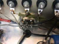
The ceramics should be removed, and replaced with larger electrolytics. 10v/1000uF is recommended. The electrolytic capacitors can be soldered directly to the "105" pads on the bottom of the board. But watch out for height issues! If the stock case is to be used, the electrolytic caps must be no more than 6mm in diameter, and lay perfectly flat against the PCB. Success has been reported with using two 470uF caps in parallel for this purpose. Pics of bottom-of-board pin7 electrolytic capacitor mods:
Alternatively, the electrolytic caps can be soldered on top of the board, directly to the tda1387 IC pins. The capacitor's negative pole goes to pin4 (ground), and the positive pole to pin7. Abraxalito's blog has a picture of this approach.


[h=Increase Decoupling of Analog Stage]%2[/h]

The stock DAC has two electrolytic and four film capacitors for opamp decoupling. Remove these capacitors and replace with as many 35V rated caps as you can fit. Find the lowest ESR you can get (Rubycon ZLH; Nichicon PW,HW; NCC KY, KZE). A well spec'ed recommendation: Nichicon UHW1V821MPD. Digikey 493-6928-ND, Mouser 647-UHW1V821MPD. Implementation pictures:

[h=Output Grounding Re-route]%2[/h]

The first item on Abraxalito's blog, "Re-route the output ground so the opamp filtering caps aren't subject to injected CM noise from the destination component (amp or pre)." More detail, along with an illustrative picture, on
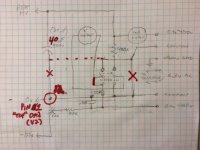
 post #6 on page 1:

Taking a look at the layout there could be a common-mode noise problem in that there are a couple of 220pF caps feeding directly into the opamps' +ve inputs from a dirty ground (the output ground). So first things first, I shall cut the thick track along the red line and route the output ground back to the trafo (indicated by the green arrow).

The pictures in post #53 on page 6 are similarly instructive.


[h=Increase TDA1387 Chip Supply Capacitance]%2[/h]

There are a couple ways to approach this (and doing both is unlikely to be a problem). The first method is analogous to the "Increase Capacitance Across TDA1387 pin7" mod above. Pin5 is the TDA1387 chip's supply voltage. You can remove the stock "104" capacitors on the back of the board and solder bigger electrolytic capacitors in their place. Post #95 on page 10 illustrates the pin5 capactors.

As of this writing, there are no pics of anyone increasing supply capacitance (pin5) on the bottom of the board. However, as with the pin7 mod, you can also solder the pin5 electrolytic caps directly to the TDA1387 IC pins on the top of the board. See post #53 on page 6 for a picture of this approach. (This picture shows added pin5 capacitance on top, directly soldered to the chip pins; and the added pin7 capacitance is on the bottom, using the "105" pads. This picture also shows added supply capacitance as described in the next paragraph.)

Another approach for adding TDA1387 IC supply capacitance is to modify the supply capacitor directly. Look again at post #53: the largest capacitor is bordred by: the heatsink to the right; the TDA1387 ICs to the top; and a big 20-pin microcontroller IC below. In this picture the cap is much larger than the stock one.

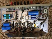
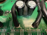
Abraxalito took this a step further, using the original capacitor's through-holes to create a "bus-bar", and hang multiple capacitors off that. From post #31 on page 4:

I've just put a dent in one remaining weakness of this DAC - the bass. Its a very simple mod to add capacitance to the TDA1387's supply. I soldered some 1.5mm copper wire to the two pads for the lytic (just beneath the chips in Matthieu's pic) and used that wire as 'bus-bar' to solder across 4 * 15,000uF 6.3V Panasonic NHG caps in a horizontal position. This tightens up the bass nicely.

This can be seen in the picture on Abraxalito's blog.


[h=Opamp Constant Current Source (CCS)]%2[/h]

From post #125 on page 13:

I'd suggest current sources on the opamp outputs as with an array of 8 DACs the opamps have to source or sink up to 8mA, well beyond classA operation of the output stage. I use the traditional two transistor current source and it goes between the opamp output pin (pin6) and the -ve supply rail.
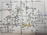
Subsequent 
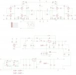
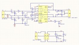
post #126 includes a circuit diagram plus more elaboration:

Here's the schematic for the classA buffer I'm using (four of) in the latest DAC mods. The two transistors at the bottom form a constant current source - its this CCS which can also be used to bias an opamp into classA. The bias current is set here by the 82R resistor for about 8mA. The transistors are literally 'two a penny' types in SOT23.

(Note the above post (#126) assumes the opamps have been removed entirely. The "four of" reference refers to one of these CCS circuits for each of the four channels (R+, L+, R-, L-) in balanced mode operation. This is an advanced modification, which will be described later in this guide.)

See post #155 on page 16 for a simplified circuit diagram of the CCS. This diagram is exactly what is needed for biasing the opamps into class-A operation; also the lines are annotated.

As for component requirements of this circuit, from post #157 on page 16:

Not all transistors will perform as well here - I look for a couple of parameters. First is 'hoe' the output impedance, indicated in Spice models by the parameter 'VAF' - we want a high number as ideally a CS has infinite output impedance. Second we don't want the transistor to have a much lower 'hoe' close to its saturation region - this can be seen on the traditional transistor curve tracer plots. I'll post up some pics later to demonstrate what's important. I don't know about Digikey's pricing but the BC817 (its a SOT23, there are leaded equivalents) is one of the cheapest going - I got a reel of them (3k) and the price was under $30 so less than a cent each.

As for resistors - almost anything will do, I'm using 0805 thick film without noticeable problems. I wouldn't advise 0603 as they do get rather noisy at higher values (like 33k). Leaded metal film will likely have better performance but as for whether you'd notice it, I can't say.

Known working parts:
NOTE: The NOS droop fillter pictured in post #218 on page 22 is erroneous. CCS circuit attachment points to opamp pins 6 and 7 are swapped (i.e. the attachment point that should go to pin7 goes to pin6 and vice-versa).

See post #269 on page 27 for a picture of a correct CCS implementation.


[h=NOS Droop Filter]%2[/h]

Many (most? all?) NOS DACs exhibit a rolloff or "droop" at the highest frequencies, typically about -3dB at 20 kHz. Here's a discussion on Abraxalito's blog.

In 
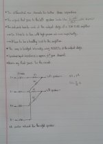
post #24 on page 3, Abraxalito proposes a filter for correcting the high frequency rolloff (aka NOS droop). Further elaboration is given in post #25. Quote from those two posts:

Here's a filter I'm going to try after the opamp - its designed to do two things. First correct for the NOS droop and second attenuate OOB images produced by the DAC. The filter that's currently on the opamp output (220R, 220pF) has a -3dB over 3MHz so isn't doing much (if anything at all) to tame the DAC's images. My filter's 2 pole and it provides 24dB attenuation at 100kHz. The inductor's a Coilcraft MSS1210. The 50k resistor isn't part of the filter itself, its my volume pot 🙂
...
I've been listening now for an hour or so and this filter's definitely for keeps. The rise in HF response makes it sound just a tad more transparent and I'm getting more of an 'in focus' sound, closer to my reference DAC.

See also post #204 on page 21 for a schematic of the NOS droop filter with annotations. Note that in that schematic, "C9999" (far right, in series with RCA connector) is the DC-blocking capacitor. The stock TDA1387 8X board already has these capacitors. They are typically square blue 2.2uF film capacitors, or in some cases axial electrolytics. If your downstream component (typically an amp) has some kind of DC-blocking mechanism (typically a series capacitor or transformer), the caps can be removed. But, if the downstream component lacks a way to block DC (e.g. a series potentiometer for volume control), the cap is needed.

As for component selection, from post #166 on page 17:

For the caps, I've used NP0 ceramics but they're SMT, you could use pretty much any film caps (steer away from mylar though) [if you] want leaded... Resistors - standard metal film leaded will be superior to the thick film that I've used.

Suggested parts:
See post #218 on page 22 for pictures of a completed NOS droop filter.

See also post #219 on page 22 for pictures of another completed NOS droop filter. This is a much neater implementation, which puts the inductor on the top of the PCB, and the RC circuit on the bottom.

See also post #270 on page 27 for yet another completed NOS droop filter.

Desktop Alpair 7p WAW/FAST woofer recommendations

I built a planet10 MarKen 10pT that I'm using as a desktop speaker now and I enjoy it, but I'd like to build something new and would like to get a little more extension in both directions. I can sacrifice some sensitivity and go slightly larger in the cabinet dimensions. The Alpair 7p is on sale at madisound right now, so I'm thinking a 19x12x11" ported box with the Alpair 7p and ~8" woofer crossed over in the 150-300Hz range. I'd like to get down to 35Hz if possible. Looking for woofer suggestions or someone to tell me this is an awful idea as I'm just learning about speaker design. The Satori MW19P-8 seems like it could be a good fit, but is fairly expensive. I'll use something in that price range if there's nothing a little cheaper that works well. Thanks for your help.

Miniature of the power amplifier LM4766 preferred

All of the power amplifier IC I like this.

Not many people like LM1875, or LM3886, more is not the TDA8920 and a digital TA2020.


Previously done much of this IC amplifiers, LM4766 is the most good. And the most simple, power can achieve +-33 V 50 W RMS 8 R. Very appropriate.

LM1875 than a much wider, close to the LM3886. And lasting appeal and the voice was very good.

DESIGN BY LJM

Attachments

  • 4766 SCH.jpg
    4766 SCH.jpg
    228.2 KB · Views: 1,384
  • IMG_2970.jpg
    IMG_2970.jpg
    262.6 KB · Views: 1,262
  • IMG_2971.jpg
    IMG_2971.jpg
    309.8 KB · Views: 1,252

Marantz PM-57 repair for a newbie

Hey all, I was wondering if someone could help me diagnose a broken PM-57 amplifier.

the power light comes on but its stopped working, no relay click, no nothing, I opened it up and using a thermal camera I noticed that the 2SB1353 transistor was very hot and then that resistors 3302(1k) and 3304(330R) had burned out, I also noticed that the two caps were bulging so i replaced these components (except the transistor) and powered it back up to see smoke coming off the board.

can anyone recomend the best procedure for fault finding this amp without damaging it further, I have a scope, frequency generator and multimeters but haven't had much experience with amplifier repairs.

Thanks in advance,

Tim

Streaming from YouTube Music – what are the options?

I have been streaming music via Volumio to a RPi DAC using BubbleUPnP, since BubbleUPnP has native support for Google Play music. Google Play music is ending and will be gone by December 2020. However, accounts (and playlists) are transferred to the new YouTube Music offering. My problem is that BubbleUPnP does not support YouTube Music.

What are the options for streaming music from YouTube Music using a RPi? Does not look like Volumio supports YouTube Music (yet), since that would be first prize, or am I mistaken? I have googled for solutions but right now my head is spinning and I don’t have anything yet. Please advise!

Babelfish M25 , AKA M2 on steroids , AKA M2-XA25 bstrd - kit packages

Presenting thread HERE

Schematic and pcb screenshot post #2 , plenty o pictures after .

Reading entire thread is advisable , same as inquiring any technical question there : Be sure that you are aware of all things electrical and mechanical !

Pcbs are not made for UMS (don't care, don't want) , mounting either on 30mmx50mm L bracket , or directly to heatsink (will show you how) , where even two bolts through mosfets are enough to hold entire shebang in place. Do not hurry - read , think , ask and only when you feel that you want it and can make it , proceed ...... advice which I'm finding applicable on practically anything 🙂


For anything else , write either here , send PM or directly to >zenmodiyaudio@gmail.com<

Prices are mostly dictated with small scale nature of operation (as always is case) and time/work involved in matching and soldering little buggers.

For ordering , contact me at above written e-mail addy .


Kit options :


1.
  • LCH pcb ,
  • RCH pcb ,
  • all smd buffer JFets presoldered ,
  • Hall current sensing chips presoldered ,
  • surrounding smd caps presoldered ,
  • 4pcs of 1uF MKC caps (for critical signal position) enclosed.

Full price , including Paypal fee and P&P for registered shipping all around the Globe - 130E

2.
  • LCH pcb ,
  • RCH pcb ,
  • all smd buffer JFets presoldered ,
  • Hall current sensing chips presoldered ,
  • surrounding smd caps presoldered ,
  • 2pcs of 1uF MKC caps (for critical signal position) enclosed.
-all multiturn trimpots
-output mosfets , 4 pcs , (I'm working on availability of Harris 9240 , but I like Vishay there)
-voltage regs
-cascode bjts
-optocouplers
-all electrolytic caps (Pana , working on availability of Silmic II for 1 position)
-one-pin sockets for special resistor positions
-all (MF 600mW) resistors

to recapitulate - everything what goes on pcbs , excluding signal xformers and pcb/mosfet mounting screws/nuts/washers

Full price , including Paypal fee and P&P for registered shipping all around the Globe - 185E


If I have everything in drawers in moment of order , can ship in 3-5 days ;
If I don't have any of normal parts in drawer , shipping could be delayed up to 3 days;
If I don't have pcbs in drawer , shipping could be delayed up to 7 days;
If I don't have most critical part for getting in my neck of wood - ACS Hall chips , shipping could be delayed up to 3 weeks.

edit , few days later - no Harris IRFP9240 , but resorted to Infineon IRFP9140

EDIT: final iteration of pcbs matched to DiyAudio UMS , final schm and pcb sshot posted in #118, Babelfish M25 , AKA M2 on steroids , AKA M2-XA25 bstrd

Bluetooth adapters and Stereo Systems

I just bought a Bluetooth 3.0 stereo receiver for a car aux port and I was really impressed with the sound, the clarity. I have gone through about six different audio cables in the last 5 years and not having to deal with broken audio cables of varying quality is not really much fun.


I want to use Bluetooth receivers for my desktop and home (vintage) system: so the question is any potential problems with this? Sound quality seems to be acceptable, but I am not sure if there are hidden distortion or quality issues here.


I simply want to connect my phone to play YouTube and streaming audio site music on my stereo.


BTW Hello there after a long break. I am not reduced to a BOSE Sound Color Bluetooth Mono speaker while I fix everything else.

Stereo separation network at the amp output - TDA7388

Hi everybody
So I'm currently desining a budget sound quality (SQ) system for my car and I was wondering if I can build some kind of passive stereo separation network for my rear channels in order to widen the soundstage and make a good use of my rear channels. The network has to go between the amp and the speakers because I don't have access to the input stage of my head unit amp.
.
What I want to achieve is a circuit that can give a decent amount of stereo separation while providing a relatively healthy load to the amplifier. In the attached photo I give my own first thoughts on the network.
.
I'm afraid that whatever resistor value we choose for the circuit, the cross-connection load will always be less than the speaker load, preventing us from achieving an acceptable result.
.
I really don't know what I'm doing so I want your help! 😕 🙂

Attachments

  • 20200916_173726-1.jpg
    20200916_173726-1.jpg
    704.7 KB · Views: 134

Kind advice needed on dc passive filtering

Hi, following the advice from a very kind Moderator of this forum i am quite decided about using dc-dc switching converters as psu.
The reason being that they switch very out of the audio band and potential residual ripple can be easily eliminated with "simple" passive filtering.
Therefore i am about to try a dc-dc switching regulator for a preamp i have at hand working with +/-24V voltage.
My question is ... will just one coil and a bypass cap to ground per rail, as in the pic attached, do the trick ? 🙄
Could someone kindly point me to a calculator for L and C values ?
Moreover ... better to place the filters close to the psu or the preamp circuit ?
Of course any advice would be very welcome
Kind regards, gino

Attachments

  • J9NjL.jpg
    J9NjL.jpg
    26.7 KB · Views: 110

thoughts on this BT\class D amplifier

guys i've gone out and ordered this, but even though its on its way, i would like to know peoples views.

ZK-TB21 TPA3116D2 bluetooth 5.0 Subwoofer Amplifier Board 50WX2+100W 2.1 Channel - US$16.99

i have the 2x50w version as well and it seems to work ok, but interested if there are any tweaks or things to look out for with these cheaper chinese 2.1ch amps. I thought it would be ok for a portable 2.1ch 12v boombox\bluetooth setup

Hornresp simulation required

Hi there!
I'm in the same situation, can't have access to a win pc easily...

I'm thinking about building two prototypes of backloaded horn with the little Faital Pro 3FE22 16 Ohm. If it turns out well I may build many of them for a sound installation...

There already a very nice project of this kind, on the avforum:
last post of the page: Stupid old man with a few good ideas.
I like the design and i think 40x42x10cm it's nice and easy to move/store/hang...
The guy use the discontinued 3FE30.

Can somebody please do a simulation with hornresp with the 3FE22 and maybe also with the 4FE32?

Thank you! Cheers

Enrico

Sony XM-45 amp?

Ran across one these on eBay and would fit my needs real nice, but damn! This thing seems to be from the early 1980's. I cannot find any info, manuals etc. on this thing.

Does anyone know anything about this antique? Any idea where I could a service manual? Right off, there are a bunch of wires, more than you would expect, so that is a bit confusing.

Thanks

Vintage article "A Tuned Pipe for Bass Enhancement" by Raymond Bates

from the 1955 Audio Anthology reprint of the original article. (and a very clean looking issue)

Norman C. Fulmer had already published an article (and patent) for an enclosure with tapered terminus.

This article borrows part of Karlson's 15 aperture for the tapered slot exit.

Subjectively the builder seemed pleased 😀

It appears to be tuned about center of the EV SP12B speaker's resonance.

I wonder how its response would really look.

Attachments

  • BATES_1_1280x.jpg
    BATES_1_1280x.jpg
    607.2 KB · Views: 297
  • BATES_2_1280x.jpg
    BATES_2_1280x.jpg
    509.6 KB · Views: 297
  • BATES_3_1280x.jpg
    BATES_3_1280x.jpg
    372.1 KB · Views: 298
  • BATES DETAIL 1.jpg
    BATES DETAIL 1.jpg
    342.7 KB · Views: 298
  • BATES DETAIL 2.jpg
    BATES DETAIL 2.jpg
    260.8 KB · Views: 290

Analog Active X-Over Question

This question goes to those who have experience with ANALOG active crossovers. Please don't turn this into a DSP thread.

Can I prototype my crossover in DSP to get the frequencies, Q, etc for a filter and then just build the analog circuit equivalent, or will the phase/delay be different with DSP than with an OP-Amp based filter?

In the end, I want an analog an not DSP crossover, but I also don't want to have to build breadboards for each iteration.

Again, I know there are a ton of DSP superfans on here, and that is not the direction I'm going.

Thanks!

WTB-Transformer set(s), OPT and Power

Hi all. I'm just getting back into tube audio after a couple year's hiatus. I'm looking to build an amp, or a couple of mono blocks. Topology isn't important, I'll go pp or se...or even pse....just looking to get north of my current system power, which is about 35wpc maxed out. Reason I'm so open is just for the joy of the build anyway, and for budget purposes. I don't want modern import opt's, so I figured I'd post here and see what anyone has sitting on their bench not being used or planned. I'd rather pay a fellow builder a fair amount and share the project than just order some 100w Hammond Cores. As for power transformers, if it's north of 200-250ma and 400v I'm game.

So yes, if anyone has a pair of some larger opt's and/or power transformer(s) please do pm me.

Thanks much everyone

Loren

Motorboating---Help Please!!

I built Leak TL/50 Plus from scratch ,point to point. The only thing I changed
is the layout: Kt88, EF86, 12ax7 KT88 in that order. All voltages appears fine.
The amp is playing wonderful untill I connect the Feedback. Then it started motorboating at a rapid pace. OK I know for sure that is connected right. It's
Edor transformer and it was in another amp. I tried many resistor but it only
stop if I use like 1 or 2 megs.
OK, I am a dilettante and I am working with only a mulitimeter. Any help or
suggestions will be appreciated.http://44bx.com/leak/Leak/Circuits/tl50_ecc83.JPG

Stereo or 2.1 PC speakers

I love listening to music and have a reasonably good audio system, but I have always wanted to build my own speakers. The thing is, I know nothing about designing enclosures to get the best out of a selected driver or drivers... and I don't want to make an expensive mess, so I figure I should start small and simple and am therefore thinking that some new speakers for my PC are in order - after all, I sit at my desk many hours a day.

My initial thoughts on the matter are that I could build a pair of stereo speakers using 3" or 4" full range drivers, perhaps augmented by a single passive sub if required (if so, I'd need to make that too).

I have a total budget of around £250 including speaker parts and the amp for the project. With respect to the amp, I'm definitely open to suggestions, but I'm thinking about something like the SMSL SA-50 if no sub is required, or something like a Dayton DTA-2.1BT2 100W 2.1 (or a cheaper alternative) if a sub is required.

So, here are the physical design limitations... because I have a large monitor and don't have any space at the sides to put any speakers, the speakers will need to fit on the desk under the monitor. For that reason, they will need to be limited to the following maximum dimensions 20cm (w) by 18cm(h) by 20cm(d) which isn't great - although I guess the height could be increased if part of the cabinet went up behind the monitor (obviously not where the driver is on it), in which case the height limit could be increased to about 45cm.

Given those dimensions and budget, do you think that I'd be able to build speakers that have a reasonably flat response and don't need a sub to get down to around 50Hz (f3)? It might be worth stating that they don't need to go very loud. If not, I could build a sub too, but that would need to fit under my desk behind a vanity panel, and for that reason, the maximum dimensions for the sub enclosure (including excursion/breathing room for the driver) are 40cm(w) by 65cm(h) by 28cm(d).

Although I have a background in physics and some experience in electronics, please treat me as a complete novice and if there are any blogs/pages/papers that you think would be good for me to read before progressing, please let me know. Reading through numerous posts on this forum, I get the impression that it takes a lot of time, experience and effort to become an expert.

Many thanks.

Transistor subs for Marantz Nineteen driver board

Hello all, I have a model Nineteen receiver that is doing excellent with the exception of one channel having offset that is all over the place. It fluctuates between -150mV and +150mV while the other channel is at 5-10mV. I removed all of the transistors from the board And measured them with a Peak Atlas DCA75 meter and they all measure okay, though they’re being measured a very low voltages. The electrolytics are new and the carbon comp resistors were replaced.

Could it be caused by something other than a transistor? A diode? A ceramic cap?

Anyways, here are the transistors on the board per manual.

34-1004
34-1005
34-1007
34-1014
MPSA56

Unfortunately Marantz part numbers make it hard to cross reference parts lol.

For the 34-1004 and 34-1005 Ive read the 2N5320 and 2N5322 would make good replacements. If that’s true, how about the MJE243 and MJE253? Specs would say they’d be equal or better.

For the 34-1007 Ive read the 2N3906BU is a good option and I have plenty of those.

For the 34-1014 Ive read the KSC945C is an option. I don’t have any of those, but have read in certain circuits the KSC1845 is good and in others the

Does anyone have a good suggestion for the MPSA56? I have a large number of transistors and hope I have something on hand.

I only really plan on replacing the transistors creating the issue. Are any of the transistors here supposed to be hFE matched? (Differential pair)

If anyone could point me in the right direction on where to start I’d be very grateful. If you’re ever in Oregon I’ll owe you a drink.

Here is a pic of the circuit and have colored the transistors

34-1004 Blue
34-1005 Green
34-1007 Red
34-1014 Orange
MPSA56 Purple


Thank you,
Dan

Attachments

  • 15BD25AA-9309-4F81-BFAE-47BA842216A1.jpg
    15BD25AA-9309-4F81-BFAE-47BA842216A1.jpg
    1,009 KB · Views: 434

PCM1795 Reset Function

Hello,

Im a bit confused with the power-on/external reset function of this DAC. In my circuit im using CS8416 as the receiver and I have the RMCK of CS8416 driving the SCK of PCM1795. Now the datasheet of the DAC says that the initialization sequence requires 1024 system clocks and after that the DAC is in its default reset state.

From my understanding this pin is only needed to set the registers in the device to their default states after power-on and these default states can be programmed before.

Now the problem is that CS8416 wont be driving the SCK pin if its not receiving anything which means that I must use the external reset since there will be a delay between power-on and system clock activation (the datasheet mentions this).

So I think I need some kind of a circuit that will supply the clock to the SCK pin and pull the RST pin low and then quit after 1024 clock cycles. But since this pin will also be connected to the RMCK pin of CS8416 Im not sure if applying voltage to this pin will damage the CS8416.

Other idea is that I have a mcu which will set up all the register on power-on then I just dont use this pin.

I assume Im either overcomplicating this and theres a simple solution or Im just not understanding the datasheet.

Can somebody give me a better idea or correct me if Im wrong?

Looking for Channel Swapping Software for Windows

I'm looking for a program that allows me to turn a couple of my surround channels into subwoofer channels (or mono, if nothing else) so I can power my subwoofers with the same amplifier (7.1 capable) as the rest of my 5.1 setup. Windows doesn't seem to have native subwoofer presets that allow anything other than a subwoofer signal that gets passed on to a dedicated subwoofer amplifier.

I'm hoping to avoid buying a second amplifier just for some decent bass! Any help would be appreciated!

Edit: I also should mention that I'm trying to do this over HDMI. My previous receiver had analog multi-channel in, so I could simply plug the subwoofer out into one of the other channels. Unfortunately, my new receiver doesn't have more than analog stereo inputs, so I'm forced to use HDMI if I want proper surround.

Simplest schematic of amp within the chip?

Hi, I've been lurking for many years with great interest in pass, jlh, susan parkers zeuss, and other simple amps (the de-lite is special imo). Now the itch to solder something is growing too strong. however i do not have a lab or testing equipment or experience. i wish to use low voltages, less than 75v but preferably around 10-36v. power is not a consideration 1-10 watts, 4-7watts would be fine. distortion as long as it is relatively benign is fine too. i really like the sansui 101 which has distortion of 0.8% i think i'll be happy if distortion is less than 4%. must be able to drive in to 2ohms. preferably class a or a/b but i'll look at others.


My main criteria is this. the chip that i want to experiment with must have the simplest internal structure possible while maybe only needing a single gain stage before or no gain stage. no opt, but input transformers is ok.


im thinking something like the ruby amp Ruby


here's a link to the pdf of the chip which shows an internal schematic https://www.ti.com/lit/ds/symlink/lm384.pdf?ts=1600199329563&ref_url=https%3A%2F%2Fwww.google.com%2F


are there any others you could recommend?


i intend to build some speakers that will be 96db efficient on average with a high qts of about 1.5ish.


many thanks and i hope you come up with some interesting suggestions!

Help with MOV expertise?

Working on non-audio problem: repair of auto Electronic Brake Control Module (EBCM).

My car is famous for common EBCM failure. The EBCM is comprised of 2 PCBs, 1 a big relay board holding 2 big 50A or so relays, and 1 an SMT micro board.

One of the specialized repair houses released this ambiguous blurb for one of their repair options:
Surge suppresion upgrade is available for your repair. This upgrade is much like the power strip on your home computer. Every time your EBCM receives power from the ignition, it goes through a number of housekeeping routines to make sure everything is working before it activates itself for operation. One of the checks that it performs is to make sure the ABS pump is attached and working correctly. For this procedure to work, the EBCM must send out voltage to the pump for a few milliseconds or just long enough for the module to determine if the pump is in good working order or not. Unfortunately, when this happens, a large voltage spike is generated by the pump. This voltage spike can be very hard on EBCM electronics. We suppress this spike so you don't have problems caused by your ABS system.

As the EBCM is quite tightly packaged, my guess is the are just adding an MOV or multiples in parallel.

I am trying to figure out which MOV model. Looking at the Bourns datasheet, the lowest voltage offered, the MOV-14D180K, has specs of:

Max Continuous Voltage: 11 Vrms, 14 Vdc
Voltage @ 1mA DC: 16 Vmin, 18 Vnom, 20 Vmax
Voltage @ Class Current: 10 A, 36 Vmax

Does this sound right? Or is the activation threshold too close to the car's operating voltage? AFAIK MOVs are used for 120V residential surge suppression are usually nominally described voltage much higher than 120V.

My car does run at 14 Vdc typical (by voltmeter I added, not stock gauge cluster).

Spark plug wire for tubes with a top cap?

Spark plug wire has well thought insulation layers very high dielectric strength, its very flexible, the boots can be repurposed to grommet into the chassis, and it looks cool and safe to the touch due to its thick insulation.

Construction-wise, there is straight copper wire, carbon core, spiral wound types and other methods of EMI reduction.


Do you think the straight copper spark plug wire would be a good choice for top capped tubes?
The wire I have just looks so dinky coming off a top cap. I'd replace the actual terminal to the tube with the correct size for the tube of course, or just fix a proper sized ceramic boot.


Constructions:

Getting Wired: Spark Plug Wires 101

A typical copper core set:

Amazon.com: JDMSPEED New 10.5mm Spark Plug Wire Set Replacement for HEI SBC BBC 350 383 454 Electronic: Automotive

Do inuke nu6000dsp speaker outputs have a common/ground?

As an alternative solution to opening up the amp and adding relays to get rid of the turnoff thump I'm looking at putting a relay on the speaker outputs.

If the speaker outputs have a common ground I could use a single relay.

I got out my DVM to check but I can't tell what's what with the hard to access Speakon contacts, and the subs are buried in walls so it's hard to check at that end.

Schematic starts on p.3 here if that helps (it's over my head):

BEHRINGER INUKE NU6000DSP SERVICE MANUAL Pdf Download | ManualsLib
Projects by fanatics, for fanatics
Get answers and advice for everyone wanting to learn the art of audio.
Join the Community
507,827
Members
7,889,912
Messages

Filter

Forum Statistics

Threads
406,326
Messages
7,889,912
Members
507,827
Latest member
Sus12