All of the power amplifier IC I like this.
Not many people like LM1875, or LM3886, more is not the TDA8920 and a digital TA2020.
Previously done much of this IC amplifiers, LM4766 is the most good. And the most simple, power can achieve +-33 V 50 W RMS 8 R. Very appropriate.
LM1875 than a much wider, close to the LM3886. And lasting appeal and the voice was very good.
DESIGN BY LJM
Attachments

I have just built this amp and hooked it to my Iphone. Serious distortion as the volume goes up past half. Any ideas
^ You might want to elaborate martingolder, like what supply voltage you used, whether the gain was the same (did you actually build exactly this amp or just use the same schematic with different values or ???), and whether you mean the volume on the iPhone or the amp itself (if not fixed value like it would be if only using the PCB).
Offhand guess is your gain is too high for the PSU voltage, or there was an assembly error or component flaw.
While there seems to be some English translation issues, I tend to disagree with the statement that "Not many people like LM1875, or LM3886, more is not the TDA8920 and a digital TA2020." Some like class D amps, some like A/B and higher output with LM3886, and some prefer more detail at lower output levels with LM1875.
Of course, some may like the tradeoff of increase in output power while retaining more definition that LM4766 provides. Otherwise they are very similar, the circuit you build around them can make more of a difference.
Any ideas
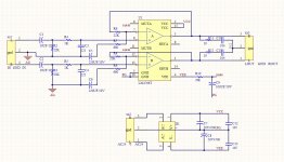
If the PCB is connected strictly according to the schematic shown then the problem could be that there's no connection between input (AG) and output/power supply (ignd) grounds.
I built exactly that amp. I am using 24VAc/1.6Amp transformer. I am using the Iphone volume control. I have tried connecting the input output grounds. I note that the amp seems to work at high volume for about 15 seconds from start and then distorts heavily. the LM4766T heats up quite a bit. I have a pentium heatsink with fan but it is not glued on yet.
LM4766 - Overture Audio Power Amplifier Series Dual 40-Watt Audio Power Amplifier with Mute
Apparently it takes the thing 15 seconds to heat up to where the "SPIKE" protection kicks in for the output power it's running at. What it's doing (the oversimplified version) is keeping the chip from destroying itself. When you properly mount it to a heat sink it won't get so hot and it won't do that.Features SPiKe Protection
It's hard to imagine that the heat sink is going to clear this up. I have held it tightly to the IC but with no heat transfer gel or cement. I am thinking that for some reason it is reaching overload too quickly because of some component value being wrong and so kicking in the Spike. I will recheck all the values and mount the sink on monday when I can get the cement. Then I will post again. Thanks everyone for your comments so far. What an amazing group of people who actually know about all this stuff in technical detail.
cheers till monday or tuesday
cheers till monday or tuesday
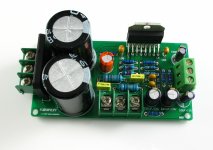
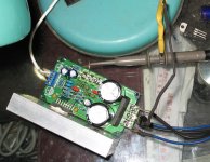
There are photos can see it, this is a most simple IC AMP
There are so many people in the use of it.
There are so many people in the use of it.
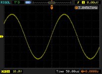
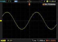
THD + N at 1 kHz at continuous average output power of 2 x 30 W into 8 0.009% (typ)
Very, very low distortion.
Very, very low distortion.
^ Every semi modern chipamp has very low distortion within a certain wattage limit... given the datasheet/spec'd/ideal power for it.
Martin.
remove your unconnected heatsink.
Clamp the chipamp between your finger and thumb, pretty tightly, keeping good contact with the metal back/interface. You are providing liquid cooling via an intercooler.
Now turn on the amplifier with the volume control turned right down for no output signal.
How warm does the chip get?
If you can keep hold in the longer term, turn the volume up slightly for some quiet music. Can you feel any increase in temperature?
Now try increasing towards that half rotation you talked about.
Have you burnt yourself yet?
I recommend that you double National's value for sink size.
remove your unconnected heatsink.
Clamp the chipamp between your finger and thumb, pretty tightly, keeping good contact with the metal back/interface. You are providing liquid cooling via an intercooler.
Now turn on the amplifier with the volume control turned right down for no output signal.
How warm does the chip get?
If you can keep hold in the longer term, turn the volume up slightly for some quiet music. Can you feel any increase in temperature?
Now try increasing towards that half rotation you talked about.
Have you burnt yourself yet?
you don't need to imagine it, just try fitting a proper heatsink as instructed by National in the datasheet.It's hard to imagine that the heat sink is going to clear this up
I recommend that you double National's value for sink size.
Still no joy
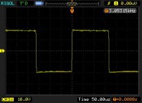
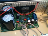
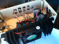
OK the heat sink sure gets the chip cool. The chip is too hot to hold without it but is now quite cool even at high volume for a while however the distortion persists.
The chip is insulated from the sink with double sided heat transmitting tape from the local electronic store. The extra wire you see is the feed to the fan.
I tried some other speakers just to be sure, I'm flumoxed. (=out of ideas!)
Attachments
Zoe_tsang who sold me the amp suggested that 1.67A 24-0-24 would be better at 3A so I bought a 3A transformer just to try (I can take it back). It didn't make any difference and I have not measured more than 1/2A from the transformer at high volume.
to ljm_ljm I see that your power supply uses a centre tap. I am just using the 24VAc to the two outer connections.
ljm_ljm I also see that your C1 and C2 are not installed ?
This without the influence, I will it short circuit.
You need to make IC surface too hot
Hi Martin,
That pic looks like it shows the heatsink separated from the chipamp thermal interface with a layer of sticky goo and the wall of the plastic casing.
This cannot get rid of much heat.
Remove the sticky goo.
Cut a hole through the plastic case. Make that hole big enough to pass the whole chipamp area through.
Now you have a choice.
1.) bolt the chipamp direct to the heatsink face, if the legs of the chip are long enough to reach all the way through.
2.) insert a copper or aluminium spacer plate that slightly exceeds the thickness of the plastic case.
Bolt the heatsink to the chipamp using that highly conductive metal spacer.
Use thermally conductive compound spread very thinly on both sides of the metal spacer. This is to keep the metal surfaces as close together as possible and to eliminate any and all air from the thermal interfaces.
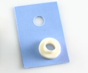
If the chipamp back face is live then the spacer and heatsink will also be live. This is at risk of being shorted to to ground or to +ve supply with careless handling.
To reduce this risk, insert a thermally conductive, electrically insulated space betwee one of the interfaces. If you use mica then both sides of the mica need thermal compound. If you use a thermal washer then you can delete one thermal compound interface.
That pic looks like it shows the heatsink separated from the chipamp thermal interface with a layer of sticky goo and the wall of the plastic casing.
This cannot get rid of much heat.
Remove the sticky goo.
Cut a hole through the plastic case. Make that hole big enough to pass the whole chipamp area through.
Now you have a choice.
1.) bolt the chipamp direct to the heatsink face, if the legs of the chip are long enough to reach all the way through.
2.) insert a copper or aluminium spacer plate that slightly exceeds the thickness of the plastic case.
Bolt the heatsink to the chipamp using that highly conductive metal spacer.
Use thermally conductive compound spread very thinly on both sides of the metal spacer. This is to keep the metal surfaces as close together as possible and to eliminate any and all air from the thermal interfaces.
If the chipamp back face is live then the spacer and heatsink will also be live. This is at risk of being shorted to to ground or to +ve supply with careless handling.
To reduce this risk, insert a thermally conductive, electrically insulated space betwee one of the interfaces. If you use mica then both sides of the mica need thermal compound. If you use a thermal washer then you can delete one thermal compound interface.
Last edited:
- Home
- Amplifiers
- Chip Amps
- Miniature of the power amplifier LM4766 preferred