Thanks Andrew. Not a very good picture. The plastic casing is cut away so that the whole PCB and chip are flush to the outside surface. The chip is tight to the heatsink with thermally conductive double sided insulating tape designed for this purpose from the electronic store.
However lying in bed this morning I had a flash. The transformer 24-0-24 is effectively a 48VAC transformer and I have a 24VAC transformer which is 12-0-12 I think.
However lying in bed this morning I had a flash. The transformer 24-0-24 is effectively a 48VAC transformer and I have a 24VAC transformer which is 12-0-12 I think.
Ok I have ordered a 48v ct transformer. My beginner confusion came from the US naming of the transformer 48V CT versus the UK naming also used in China 20-0-24.
The datasheet says split rail 30,0,30vdc (60vdc total). For that, you start with a 20,0,20vac center tap transformer.
You might could use a 22, 22, dual secondaries transformer with dual snubbed bridge rectifiers for creating a split rail 31,0,31vdc supply (62v total).
Unfortunately the 48vct, a 24,0,24 center tap transformer is too much voltage, can result in a 35,0,35 vdc split rail supply (70v total) and can burn the chip.
But, don't take my word for it--check the datasheet.
EDIT. The needed transformer is less common. Maybe these examples will help:
EI core example
http://www.alliedelec.com/search/productdetail.aspx?SKU=9288566
Toroid example
http://www.antekinc.com/pdf/AN-2220.pdf
Last edited:
Anyone else want to comment on danielwritesbac's comments?
I don't understand how a 24-0-24 ends up as 35-0-35
The rectifier circuit is already built into the PCB see above.
I don't understand how a 24-0-24 ends up as 35-0-35
The rectifier circuit is already built into the PCB see above.
DC output voltage when delivering near zero current is = [Mains input voltage/transformer rated input voltage * transformer rated secondary voltage * {1+transformer regulation} * mains maximum tolerance * sqrt{2}] - diode voltage drop.
If you use the electricity suppliers maximum tolerance for your supply input voltage you can see your worst case High DC voltage. You also should look at worst case Low DC voltage, and include an output current this time.
If you use the electricity suppliers maximum tolerance for your supply input voltage you can see your worst case High DC voltage. You also should look at worst case Low DC voltage, and include an output current this time.
The absolute max supply voltage spec'd is 74V (with input). BUT, the overall design including heatsinking is for less, if you try to "tweak" output higher than the design target it was just the wrong chip to use! WHY OH WHY do people keep thinking let's try to push the limits?? it's crazy but I digress...
Now about actual implementation. What is fit vs wasted power depends on the (speaker) load. Can you do XYZ? Maybe, but why not build optimal for the load considering that in the end, time or electricity cost will make it worthwhile?
We seem to keep seeing posts about "I want to use some part not suited to build something to save on build cost".
The MUCH saner thing to do if you want to (re) use parts you have, is to consider their optimal use and build around THAT. I know this is a generic-like reply but in the end spending too much time on something becomes counter productive... unless you are stranded on a remote desert island and HAVE to make it work... and if you are stranded, we can probably arrange someone help to rescue you. 😉
referring back to ljm_ljm who built exactly the same amp and used 24-0-24. He says thats Ok. Since this is a kit that is used a lot and recommends 24-0-24 I am inclined to go with it. I used to be a hobbyist in the dark ages before IC's and in fact saw some very early IC's in petrie dishes at MIT in 1964. I am enjoying returning to having my desk covered with meters and wires and PCB's etc. I can see that this site is an awesome resource and I have this memory of being able to speak this language. Thanks for weighing in. Cheers
There's no guarantee of success on the following prospect to drop 1 or 2 volts:
Cut the center tap link to form a "dual secondaries" transformer.
Use 1 of KBPC1004 (or BR84) per each secondary (2 rectifiers to purchase because there are 2 secondaries).
Further drop voltage by dropping noise--install 10nF inexpensive polyester dip cap parallel to each diode. There will be 8 of these little caps to purchase.
Arrange the clearly marked rectifiers as if they are the batteries in a 2-cell flashlight. The point between is the 0v line. You can now begin your split rail supply.
You are at 1 or 2 volts lower because of decreased noise. Both lower voltage and decreased noise are good things. Unfortunately, this approach is insufficient for your application.
Instead, do you favor using a voltage regulator and/or cap-multi power supply?
Those are more elegant and can remove more excessive voltage.
Success
The transformer arrived 48V CT or 24-0-24 Big unit. Works perfectly.
I just played 1812 cranked all the way with good clear sound and very little heat detectable from the pentium heatsink with fan. I powered the 12v DC fan from one side of the transformer with a single diode. works fine. seems to see about 10vdc.
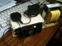
Anyway the picture shows final unit with the monster transformer, the heatsink and fan and the bluetooth receiver and power supply.
Thanks for you help
The transformer arrived 48V CT or 24-0-24 Big unit. Works perfectly.
I just played 1812 cranked all the way with good clear sound and very little heat detectable from the pentium heatsink with fan. I powered the 12v DC fan from one side of the transformer with a single diode. works fine. seems to see about 10vdc.
Anyway the picture shows final unit with the monster transformer, the heatsink and fan and the bluetooth receiver and power supply.
Thanks for you help

Martin did you use the mute feature and R10, C9 on the schematic? That's on the negative power rail, if you implemented it do you have the fan on the positive power rail instead where it is pulling positive rail voltage down faster?
The spec sheet calls for 0.5mA per pin (channel), 1mA combined to stay out of mute mode. Plugging into the datasheet equation your R10 with that transformer could be raised to 30K, but try it with the fan disconnected and swap fan supply to negative power rail & gnd. if that helps.
The spec sheet calls for 0.5mA per pin (channel), 1mA combined to stay out of mute mode. Plugging into the datasheet equation your R10 with that transformer could be raised to 30K, but try it with the fan disconnected and swap fan supply to negative power rail & gnd. if that helps.
Last edited:
I disconnected the fan completely but the pop on power down is still there. The R10 and C9 are installed.
^ You might measure the voltage at C9 (negative pin) to see what it is when the pop occurs. As per the datasheet, increasing the R10 value should raise the voltage level at which the amp goes into mute mode, to the end of having it mute before it pops.
I don't remember your source though, do you have it powered by a separate power supply or subcircuit so when you are turning it off, it turns off faster/sooner than the amp power supply circuit drains?
I don't remember your source though, do you have it powered by a separate power supply or subcircuit so when you are turning it off, it turns off faster/sooner than the amp power supply circuit drains?
Last edited:
The source is a bluetooth receiver and when either the power or 3.mm audio plug are disconnected the pop is gone. Unplugging the power from the receiver when the amp is on induces the pop. So I am thinking that I need to cause the power to the receiver to remain on for a second after the amp is powered down or ?
Yes, but the time period depends on how fast the amp PSU drains, it could be more or less than a second needed. With 4700uF capacitance on the power rails and the R10 resistor at 20KOhm I suspect it would take longer than 1 second, but someone more ambitious can probably calculate how long it would take given no input signal.
The schematic for the amp PSU seems minimalistic, some people add bleeder resistors across both the positive and negative rails to ground as an amp without a source signal (or quiet) could drain power very slowly, but even with bleeder resistors the amp PSU could easily take more time to drain till mute kicks in than it takes for the source power to collapse causing the pop, unless your bleeder resistors were low enough ohm that they consume a lot (too much, probably) power and create too much heat to be reasonable. Even so, I like having bleeder resistors so you know that after the amp is off the capacitors completely drain in a reasonable amount of time.
Another option or additionally, you could use a relay powered by the source PSU to mute it, so when source power is off the relay opens causing the amp to go into mute mode (put relay between R10 and negative power rail or between R10 and the amp mute pins 4 & 6, I'd probably just take R10 off the PCB and use the two pads for wires to connect to the relay and R10 air-wired to it if not on a separate PCB).
Last edited:
fit an instant mute on loss of power that shorts the input signal hot to input signal return.
What might that look like? a transistor switch?
I was thinking maybe a 50mf capacitor and 100ohm resistor across the 5v input to the bluetooth receiver to cause a softer power down spike.
- Home
- Amplifiers
- Chip Amps
- Miniature of the power amplifier LM4766 preferred