Hi all,
After completing an Aleph J and F5 over the past few years, I've decided to take the next step and build a pair of F5 Monoblocks.
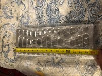
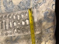
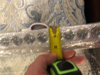
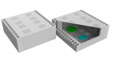
I've purchased some really interesting aluminum cases with Boulder-style heatsinks, which you'll see in the attached pictures. These heatsinks are very heavy, and measure about 6 inches tall and 15.5 inches deep. They are about 2 inches wide.
I bought these primarily for ascetic reasons, and I have no idea how good they will be at dissipating heat. Does anyone have experience with heatsinks of this type?
I'm not set on making each channel 100W, but I'd like to make them as powerful as possible without risking overheating.
Any thoughts on what the right rail voltage would be for heatsinks of this type? I figure, at a minimum, I could do 50W per monoblock and use the standard 24V rail voltage for the F5. But I'd like to push higher than that if possible.
Any recommendations would be appreciated before I spend the money on transformers.
Thank you!
After completing an Aleph J and F5 over the past few years, I've decided to take the next step and build a pair of F5 Monoblocks.
I've purchased some really interesting aluminum cases with Boulder-style heatsinks, which you'll see in the attached pictures. These heatsinks are very heavy, and measure about 6 inches tall and 15.5 inches deep. They are about 2 inches wide.
I bought these primarily for ascetic reasons, and I have no idea how good they will be at dissipating heat. Does anyone have experience with heatsinks of this type?
I'm not set on making each channel 100W, but I'd like to make them as powerful as possible without risking overheating.
Any thoughts on what the right rail voltage would be for heatsinks of this type? I figure, at a minimum, I could do 50W per monoblock and use the standard 24V rail voltage for the F5. But I'd like to push higher than that if possible.
Any recommendations would be appreciated before I spend the money on transformers.
Thank you!
Attachments

Those are lovely& I’d estimate around 50 watts or more easily - that’s a lot of metal and in a pinch you could always dial back the bias a bit.
The thermal interface between the devices and the sink is important to get right, so spend as much time on that as you can !
The thermal interface between the devices and the sink is important to get right, so spend as much time on that as you can !
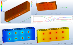
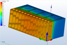
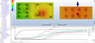
Did you make any decisions on your configuration yet? I'm starting to get into CFD analysis for my own case designs and I did some rough modeling of your plate to get some of the bugs worked out of my process. I am still not dialed in with a workable enclosed/vented case YET. But in terms of bare bones thermal performance I think the model is looking pretty good.
The first pass was without thermal pads and the final pass was with a thin film resistance based on the spec of those Red pads offered at the Diy store. The first run stabilized at 73C and it creeped up to 75 with the pads.
The general setup is as follows:
Plate-6061 Al
Transistors-silicon @ 12.5W each
Ambient air temp - 25C
Natural Convection
Spacing based on the Diy universal mounting guide for the F5
The plate in my model weighs 10.6 pounds so if you can weigh your plate we could get a good idea of how accurate my geometry is. The general hole features are 1" dia. with a 1.175" spacing and an overall size of 15.5 x 6 x 2.
Do you have a target temp for the transistors? How about an expected max ambient temp?
Attachments
Haze Head,
This is amazing! Thank you! I will get back to you with more details! 25 degrees C is a fair ambient estimate. The heat sinks are in NY, but I will weigh them when I return next week.
What do other recommend for target temp for transistors in F5 turbo?
Thanks again.
This is amazing! Thank you! I will get back to you with more details! 25 degrees C is a fair ambient estimate. The heat sinks are in NY, but I will weigh them when I return next week.
What do other recommend for target temp for transistors in F5 turbo?
Thanks again.
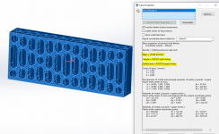
Getting a strong suspicion that each one of those plates is designed specifically to handle 50W. I stumbled onto an interesting coincidence that is perhaps more than just coincidence. Having put 50W total into the four center chips the plate temp stabilized in the 50-56C region. Doing a little digging, the Boulder 1161 stereo amp [$22,000 😀] shows a very similarly sized plate, and of course the same geometry (glad you mentioned Boulder).
The 1161 is rated for 150wpc, but they do not mention any details about class and so on. Then I came across this review: The Boulder 1161 Power Amplifer – Reviews | TONEAudio MAGAZINE
They must have teased the spec. out of Boulder because they put the 1161 at 17W in pure Class A. Here is where it gets interesting. The following is found on the First Watt site:
"At Pass Labs the bias is set to the value which raises the heat sinks 25 – 30 degrees C. above ambient temperature. The result is a heat sink which you can put your hand on for about 10 seconds or so.
As a practical matter, this means that our X (Class AB) amplifiers are biased to
dissipate roughly half of their rated output power. The XA (Class A) amplifiers are
biased to dissipate roughly three times their rated output power."
Not sure if the same "times 3" rule applies to the F5 (lots thermal info. in the F5 manual to digest still); if it does however, that 50W plate rating will knock your Class A output way back down to 17W per plate! I'll mention one more time that I'm a noob with thermal simulations as well as circuit topology and could be way out in left field, so there's that. Maybe someone can jump in with more insight? Whatever the case, arriving 17W [16.7W] Class A (based on the Pass 3x rule), independently, and then finding the original design application to be right on that number put one helluva smirk on my face lol-
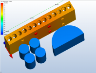
Attached is a half enclosure (your case cut down the center) with 12.5W pure waste heat going into each of the four center chips (assuming 2 plates with 4 chips each for the mono) for 50W total heat energy.
If you want to go with more power and keep within the recommended Pass guidelines there are probably a dozen ways to go about it. Fans would be a no-brainer, whether or not that would be blasphemy is another matter. Personally I'm getting into liquid cooling applications because I come from the PC mods gang where managing 100 plus watts of pure waste heat in a small package is fairly pedestrian. What the world really needs is micro F5v3 cooled with liquid nitrogen!
The 1161 is rated for 150wpc, but they do not mention any details about class and so on. Then I came across this review: The Boulder 1161 Power Amplifer – Reviews | TONEAudio MAGAZINE
They must have teased the spec. out of Boulder because they put the 1161 at 17W in pure Class A. Here is where it gets interesting. The following is found on the First Watt site:
"At Pass Labs the bias is set to the value which raises the heat sinks 25 – 30 degrees C. above ambient temperature. The result is a heat sink which you can put your hand on for about 10 seconds or so.
As a practical matter, this means that our X (Class AB) amplifiers are biased to
dissipate roughly half of their rated output power. The XA (Class A) amplifiers are
biased to dissipate roughly three times their rated output power."
Not sure if the same "times 3" rule applies to the F5 (lots thermal info. in the F5 manual to digest still); if it does however, that 50W plate rating will knock your Class A output way back down to 17W per plate! I'll mention one more time that I'm a noob with thermal simulations as well as circuit topology and could be way out in left field, so there's that. Maybe someone can jump in with more insight? Whatever the case, arriving 17W [16.7W] Class A (based on the Pass 3x rule), independently, and then finding the original design application to be right on that number put one helluva smirk on my face lol-
Attached is a half enclosure (your case cut down the center) with 12.5W pure waste heat going into each of the four center chips (assuming 2 plates with 4 chips each for the mono) for 50W total heat energy.
If you want to go with more power and keep within the recommended Pass guidelines there are probably a dozen ways to go about it. Fans would be a no-brainer, whether or not that would be blasphemy is another matter. Personally I'm getting into liquid cooling applications because I come from the PC mods gang where managing 100 plus watts of pure waste heat in a small package is fairly pedestrian. What the world really needs is micro F5v3 cooled with liquid nitrogen!
Attachments
If the heatsinks are good for 50W each at 30 degrees above ambient
That's 100W per monoblock
At 25V rails you could bias 2A
At 32V rails you could bias around 1.5A
That's 100W per monoblock
At 25V rails you could bias 2A
At 32V rails you could bias around 1.5A
Getting a strong suspicion that each one of those plates is designed specifically to handle 50W. I stumbled onto an interesting coincidence that is perhaps more than just coincidence. Having put 50W total into the four center chips the plate temp stabilized in the 50-56C region. Doing a little digging, the Boulder 1161 stereo amp [$22,000 😀] shows a very similarly sized plate, and of course the same geometry (glad you mentioned Boulder).
The 1161 is rated for 150wpc, but they do not mention any details about class and so on. Then I came across this review: The Boulder 1161 Power Amplifer – Reviews | TONEAudio MAGAZINE
They must have teased the spec. out of Boulder because they put the 1161 at 17W in pure Class A. Here is where it gets interesting. The following is found on the First Watt site:
"At Pass Labs the bias is set to the value which raises the heat sinks 25 – 30 degrees C. above ambient temperature. The result is a heat sink which you can put your hand on for about 10 seconds or so.
As a practical matter, this means that our X (Class AB) amplifiers are biased to
dissipate roughly half of their rated output power. The XA (Class A) amplifiers are
biased to dissipate roughly three times their rated output power."
Not sure if the same "times 3" rule applies to the F5 (lots thermal info. in the F5 manual to digest still); if it does however, that 50W plate rating will knock your Class A output way back down to 17W per plate! I'll mention one more time that I'm a noob with thermal simulations as well as circuit topology and could be way out in left field, so there's that. Maybe someone can jump in with more insight? Whatever the case, arriving 17W [16.7W] Class A (based on the Pass 3x rule), independently, and then finding the original design application to be right on that number put one helluva smirk on my face lol-
Attached is a half enclosure (your case cut down the center) with 12.5W pure waste heat going into each of the four center chips (assuming 2 plates with 4 chips each for the mono) for 50W total heat energy.
If you want to go with more power and keep within the recommended Pass guidelines there are probably a dozen ways to go about it. Fans would be a no-brainer, whether or not that would be blasphemy is another matter. Personally I'm getting into liquid cooling applications because I come from the PC mods gang where managing 100 plus watts of pure waste heat in a small package is fairly pedestrian. What the world really needs is micro F5v3 cooled with liquid nitrogen!
Haze head,
You were very close! They weigh about 11.5 pounds each.
If the heatsinks are good for 50W each at 30 degrees above ambient
That's 100W per monoblock
At 25V rails you could bias 2A
At 32V rails you could bias around 1.5A
I was thinking about using 35V transformer which will give me 48V rails. Is that too high for this enclosure?
You would need to bias at 0.5 A for a 50W rated heatsink
That's not really optimal unless you really absolutely needed 48V rails.
Maybe determine what you actually need.
What speakers do you have etc.
Alternatively buy 2 of those cases and do mono blocks or get the biggest 5U chassis you can buy, and save that chassis for another project.
A few options there.
Last edited:
Sorry for confusion, but I did buy two and am planning monoblocks. Does that change answer at all on the rail voltage?
Sorry for confusion, but I did buy two and am planning monoblocks. Does that change answer at all on the rail voltage?
Yeah so 1A per channel (mono block) at 48V rails.
That might be ok.
40V rails (with 1.25A Bias) would be more optimal most likely, depending on speakers.
If it was me, I would go with 32V rails and 1.5 A, but if you really need the extra voltage then that is different.
Basically if your speakers are 87dB, 32V would be more than enough, and you will get a greater class A region.
If your speakers were 83dB then yeah you'll probably want 48V rails, but biasing is not the most optimal.
Last edited:
Just clamp a known Dissipator on one, preferably adjustable. Now you can measure real world the performance. maybe a mock biased output stage or a big aluminium power resistor?
Yup. Barbaric but you would be sure. 🙂
Yup. Barbaric but you would be sure. 🙂
I did something similar with one of my heatsinks and then simulated the model next to a rough estimation of the mystery heatsink. Matching the simulation up to the actual result at 99w input, I then throttled back the power until the mystery plate was about 55C. IIRC, the total power came out around 80W-88W. Seems like the range of the model is 50W at the low end up to 90W on the extreme high end, depending on how much ambient airflow is being exchanged around it.
Looking forward to seeing whether these simulations are viable or just a good way to trick oneself with pretty charts and graphics 😀
Looking forward to seeing whether these simulations are viable or just a good way to trick oneself with pretty charts and graphics 😀
Attachments

I think if you get the heatsink surface area right, I would expect the simulated result to be within 10% of reality.
In the end it doesn't matter too much, he has to work with what he has, which is basically bias the thing for around 55C operation, whatever that ends up being is what he'll have to work with.
In the end it doesn't matter too much, he has to work with what he has, which is basically bias the thing for around 55C operation, whatever that ends up being is what he'll have to work with.
@ 2 picoDumbs
What I noticed with doing simulations before physical tests vs after is that accounting for the exchange of air volume is the tricky part. Currently I'm having to add a fair amount of exchange to bring the temps down to the
physical measurement. The simulated temps out of the box are about 10C above the actual, until the circulation is cranked up.
If it lands within 10% of actual that would be pretty cool. Unfortunately my model is about 8% undersized from the actual so that will tend to muddy the result. Much below 90% accuracy is probably not worth the time when it's so easy to pump a dummy load into the actual plate and get the number.
I'm curious, if the plate will actually handle 10W per chip (on the high side) for a total of 80W.....what is that in "class A" output? Or, to know that value would the resistor in water test be required?
I'm curious, if the plate will actually handle 10W per chip (on the high side) for a total of 80W.....what is that in "class A" output? Or, to know that value would the resistor in water test be required?
80W disspation will give around 35W to 40W Class A for a push-pull circuit, if set up correctly. It could be less if the circuit can't swing all the way to the rail voltages.
That's per channel.
160W total dissipation for 35W to 40W for Class A stereo, in a near perfect circuit. F5 won't be quite as good as that.
In Eliasb's situation it seems he is prepared to give up some Class A power for added Class AB power.
Nothing wrong with that if his speakers need that sought of extra voltage. It's a balancing act between bias currents and rail voltages to get the best result. Very much determined by the speaker.
Last edited:
@ 2 picoDumbs
Considering the M2 is push-pull as well; if my M2 is running on 19.5V rails and the total power input is 54W than is it safe to assume the output is around that rated 25WPC figure?
Seems surprisingly efficient! I must be missing something....
Considering the M2 is push-pull as well; if my M2 is running on 19.5V rails and the total power input is 54W than is it safe to assume the output is around that rated 25WPC figure?
Seems surprisingly efficient! I must be missing something....
Is that 54W per channel?
It's probably closer to 20W
How are you determining this input power figure?
It's probably closer to 20W
How are you determining this input power figure?
Last edited:
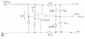
Correct, I just have a single channel built. It's a pure DC source "off-grid" build and Zen Mod hooked me up with a cool hack to generate that negative rail; see here https://www.diyaudio.com/forums/pass-labs/359411-m2x-powered-dc-source-2.html#post6345721
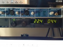
54W is coming out of the Sorensen benchtop supply measuring 39VDC @ ~1.37A. That feeds voltage dividers that power an audio amp that converts one of the rails over to -V.
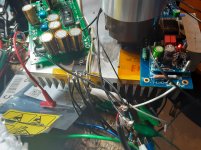
Power at the M2 is ~19.5V per rail. I'll attach a pic of Zen Mod's circuit-
Edit: had to throw in a pic of the grungy beast!
54W is coming out of the Sorensen benchtop supply measuring 39VDC @ ~1.37A. That feeds voltage dividers that power an audio amp that converts one of the rails over to -V.
Power at the M2 is ~19.5V per rail. I'll attach a pic of Zen Mod's circuit-
Edit: had to throw in a pic of the grungy beast!
Attachments
Last edited:
- Home
- Amplifiers
- Pass Labs
- PSU Voltage for F5 Turbo Monoblocks with Unusual Heatsinks