You are using an out of date browser. It may not display this or other websites correctly.
You should upgrade or use an alternative browser.
You should upgrade or use an alternative browser.
Filters
Show only:
Audio Precision 2522 - Need Service Manual
- By mp006ltk
- Equipment & Tools
- 3 Replies
Does anyone have the service manual or schematic for the Audio Precision System 2? I can find the System 1 all over the internet, but nothing on the System 2. I've seen a picture of it in a binder, but nothing downloadable including the AP website.
Sympatico amplifier - impressions?
- By supernet
- Twisted Pear
- 66 Replies
I am thinking of buliding stereo (later active) 2 way system for my friend, using Sympatico amplifier modules. It will be feed through balanced connections with DAC/preamp or miniDSP. Since I have not get yet any listening experiences using LM4780 in such configuration, I am asking Sympatico builders about their opinions about this project, which loudspeakers are you using and how far should I put sound performance expectation?
Thanks in advance.
Thanks in advance.
EL84 and 6V6 in parallel???
- By youngb4
- Instruments and Amps
- 137 Replies
Hello everyone,
I've been working on some simple single ended guitar amp designs over the past few months and I really want to try running a 6V6 and an EL84 in parallel for the power amp section! I've drawn a rough schematic and attached it to the post, so can someone take a look real quick and let me know if I'm on the right track and if this can be done?! I know I'll need an ideal primary impedance of 3000 ohms on the OT, but the hammond 125ese can be had with a 2500 or 5000 primary so that should be close enough right? As I said before the schematic is purely conceptual, I haven't breadboarded anything yet, I just want some people's opinions on whether this can be done with no issues and also if there are any recommended changes to my design.
Thanks for your help and comments in advance!
Attachments
Netflix, The Social Dilemma, is the most important documentary of our times
- By olsond3
- The Lounge
- 79 Replies
Remember how the people who invented the atomic bomb came out later saying that they regretted it. I was reminded of that after watching the creators of social media interviewed in "The Social Dilemma" now available on Netflix. I found it terrifying. It is not perfect or anything, but watching the people who built the machine describe how it works and what it is really doing is a must see. I have worked in software for many years, I had only a vague idea of what was going on. It is too long, and too polished, but that may appeal to the widest audience. If you have ever spent time developing an algorithm that optimized something, you understand how badly single parameter blind optimization can go wrong. Imagine how long it would take an optimization algorithm with the only goal of maximizing the acceleration of a car to figure out that running into a solid wall gives the peak acceleration. Look around at your family and friends and see if you can pry them away from social media for a day. Go ahead and try. Turn off the internet at your house, you will find yourself alone in a few hours as the others go find internet elsewhere. Remind you of a gambling addiction?
Zaph’s ZRT
Just wandering if anyone has a different crossover for exactly same drivers arrangement dual 18w8531 and 6600 aircirc tweeter It can be 2way ,2.5 way or even 3 way. Not looking for computer simulations. Thx for reading my post
Technics SU Z780
- By Cliffwag118
- Solid State
- 7 Replies
I have an oldie but a goodie Integrated Power Amp Technics SU Z780. The power On/Off switch (ESB8249V) fails to remain making contact and of course the amp goes off. If I hold the power button in, the unit will stay on. I can't find this switch or any replacement on the market. I am hoping someone has an idea where I might get one.
Elekit TU-8500 Best buy Award
Moon and Stereo
Best Buy Award
Mono and Stereo High-End Audio Magazine: THE GREATEST BANG FOR THE BUCK - ELEKIT TU-8500 REVIEW

Best Buy Award
Mono and Stereo High-End Audio Magazine: THE GREATEST BANG FOR THE BUCK - ELEKIT TU-8500 REVIEW
Can get negative voltage from HD Plex 300
- By fdojose
- Power Supplies
- 9 Replies
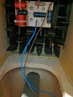
Hi guys, I need your advise, for a project I need +5v gnd -5v, I have a HD Plex 300w power supply and I´d like to use it, but it only give + voltages.
Do you know if there is a way to get a negative voltage from any where inside that psu?
I know I could do it with an oscilator, diodes and capacitors, but could be more elegant just to get it from psu.
Thanks,
Do you know if there is a way to get a negative voltage from any where inside that psu?
I know I could do it with an oscilator, diodes and capacitors, but could be more elegant just to get it from psu.
Thanks,
WTB: DIYtube Get Set Go PCB
Hi
Looking for 1 pcb (unpopulated or used) for a pair of 6B4G I’d like to listen to...
Please send me a PM if you have one you don’t intend to use.
Thanks
Eric
Looking for 1 pcb (unpopulated or used) for a pair of 6B4G I’d like to listen to...
Please send me a PM if you have one you don’t intend to use.
Thanks
Eric
B&G Neo 3/Pdr fails
- By WrineX
- Planars & Exotics
- 0 Replies
I was constructing a new metal plate for a test. and took another look at the B&G neo 3 PDR.
Why are they so efficient and why do my measurements of them look so bad?
well here is the answer. i dont know how old they are to be honest.
RECTIFICATION! , i say somewhere 1.5 Khz at 1 watt. that should be 2.85 volt. in this case being 4 ohms ~ means 2 watt.
- i say it distorts insanely at 1.5khz.. it is actually 3 Khz..
Common B&G Neo 3/PDR Planar Tweeter failures - YouTube
Audiostatic, dot problems
- By clog
- Planars & Exotics
- 13 Replies
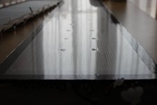
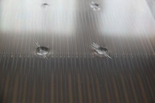
Recently I rebuild a pair of Audiostatics ESH100. An almost full range electrostatic with integrated bass reflex for the lowest octave.
Listening to the end result I noticed that one of the ESL's had a lower output and that when playing louder distortion is occurring sooner than on the other one.
To stabilize the diaphragm Audiostatics applied silicon dots between the wire stator and the diaphragm. Upon inspection it turned out that on the low output speaker the silicone dots were much bigger than on the other one. And what's more it looks like the dots are sucking the diaphragm closer to one side of the stator. The pictures are showing clearly that the silicon sealant is producing dents in the diaphragm. In my opinion caused by shrinking of the sealant.
I would appreciate to get some help about alternatives, like advice about non shrinking (clear) silicon kit or paste, the use of double sided foam tape or perhaps the use of kneadable rubber/putty.
Attachments
ALD's Double Inverted ChipAmp
- Chip Amps
- 12 Replies
Howdy Neighbours,
Just fer giggles, let's try this:

..puttin' the DIY BACK into diyaudio...
Hun, so this is a REcreation of " "T's" Inverted GainClone ". It obliviously wasn't his, but rather somebody took his idea of an inverted gainclone power amp and thru a pot on the front ...


 ...
...
Doh! [1st Task: why is this 'amp' unstable? ]
So I recall T noting (re his power amp) that using an opamp [no matter signal or power] in invert. config. has some advantages:
A) You can choose the values on the +input so they match the -input's (better balance; tweak by actual measurement)
B) Invert. operation provides that nifty virtual ground that, because of the fet input, physically ACTS almost IDEAL [acting purely mathematical, with no real-world 'fudge' factor] and thus has these tech. advantages ... blah, blah, blah, ... I can't recall what he said.
...oh, oh , and I thought:
C) Well, because [in this particular case] the pot sets the input impedance, Rin and Rf can be dropped by an order of magnitude to provide better noise and more current through the resistors [and junction] that provides further benefit by ... blah, blah, blah, I can't recall what I thought. ;}
D) So I'd like to correct and develop this circuit and build it and do some basic testing and listening and ... and, d o i t m y s e l f , ... if ya know what I mean ...
Cheers from the
ALD
man!
PS And YES that's how yer supposed to spell n e i g h b o U r s!!11!1!
PPS It's not DOUBLE inverted .... Yet!
PPPS This project wasn't getting much traction in the Loungy thread sooooooooooo ..................
Just fer giggles, let's try this:
..puttin' the DIY BACK into diyaudio...
Hun, so this is a REcreation of " "T's" Inverted GainClone ". It obliviously wasn't his, but rather somebody took his idea of an inverted gainclone power amp and thru a pot on the front ...
... Doh! [1st Task: why is this 'amp' unstable? ]
So I recall T noting (re his power amp) that using an opamp [no matter signal or power] in invert. config. has some advantages:
A) You can choose the values on the +input so they match the -input's (better balance; tweak by actual measurement)
B) Invert. operation provides that nifty virtual ground that, because of the fet input, physically ACTS almost IDEAL [acting purely mathematical, with no real-world 'fudge' factor] and thus has these tech. advantages ... blah, blah, blah, ... I can't recall what he said.
...oh, oh , and I thought:
C) Well, because [in this particular case] the pot sets the input impedance, Rin and Rf can be dropped by an order of magnitude to provide better noise and more current through the resistors [and junction] that provides further benefit by ... blah, blah, blah, I can't recall what I thought. ;}
D) So I'd like to correct and develop this circuit and build it and do some basic testing and listening and ... and, d o i t m y s e l f , ... if ya know what I mean ...
Cheers from the
ALD
man!
PS And YES that's how yer supposed to spell n e i g h b o U r s!!11!1!
PPS It's not DOUBLE inverted .... Yet!
PPPS This project wasn't getting much traction in the Loungy thread sooooooooooo ..................
Portable hifi speaker
I'm new to diy speakers, only starting down this rabbit hole a week or so ago. I want to build a high end portable bluetooth boombox. Something that will wow me and my family that I can bring along when we go on trips or parties.
This is my list so far
Monoprice Premium Bluetooth 5 Transmitter & Receiver- for the bluetooth
minidsp 2x4 hd - using it as crossover
ICEpower 50ASX2SE - for the tweeter and midrange
ICEpower 125ASX2 - for the woofer
Drivers
ScanSpeak 15W/8530K-00 - midrange
ScanSpeak Illuminator D3004/6040-00 or the be version if that is worth the extra 200$
not exactly sure what woofer to get
Currently considering passive radiators or ported but not entirely sure what the advantages and disadvantages are. Also considering just using a predesigned center speaker and modifying it somewhat to make it bluetooth and portable.
spray paint a driver and passive radiator?
- By SNIRAVIV
- Subwoofers
- 13 Replies
Dayton Audio SD215A-88 8"
+
Dayton Audio DSA215-PR 8"
do you think i can just spray paint them ? will need 2-3 coats of paint i guess
+
Dayton Audio DSA215-PR 8"
do you think i can just spray paint them ? will need 2-3 coats of paint i guess
WANTED: DCA75 Pro Tester
Following the suggestions that everybody should have one 😀
Situated in Spain, payment PP gift or SEPA transfer.
Thank you.
Situated in Spain, payment PP gift or SEPA transfer.
Thank you.
Correct Sealant Glue I Need
- By Mr Streekz
- Multi-Way
- 4 Replies
Hi and good morning all
ive aquired a pair of B&W DM305 Floorstanders and 1 of the prism back panels vibrates at certain bass frquencies ive taken the driver out and can see that B&W only glued them top and bottom of cabinet to the prism piece and not to sides which seems to be where the vibration occurs ive taken a pic of original glue but not sure what it is or what i could use instead to reseal the sides inside to try and stop vibration. Obviously i need a longish nozzle to be able to get inside cabinet and reach past prisms to reach sides.
Any help would be appreciated
Attachments
Tony gee's humble optimo?
Greetings from Indonesia.
I am interested to build my first diy loudspeaker. And I stumbled on this optimo design. These drivers are commonly available here in Indonesia, so I think I will give it a shot.
Can someone help me with higher resolution pdf on the built sheet, concerning the measurement of the box please..?
Many thx before
WTB: Teabag diode bridge TO247
I have some MUR3020 diodes I want to use in an upcoming dual mono PSU build, does anyone has ie. the Teabag PSU diode bridge PSU for offer, not the complete PSU, would appreciate that
My post on Karlson - Oliver "klam" projector speakers
- By freddi
- PA Systems
- 3 Replies
perhaps there's someone here who remembers them.
https://www.diyaudio.com/forums/ful...-rocket-rise-klam-projectors-post6343074.html
https://www.diyaudio.com/forums/ful...-rocket-rise-klam-projectors-post6343074.html
I suppose I should introduce myself :D
- By NickKUK
- Introductions
- 3 Replies
I thought I'd finally say hello 🙂
I'm a complete novice & beginner but also curious - which can be a very annoying combination for experts. Why? 😀
Creating a small headphone capable DAC/Amp is on my list of things todo, which according to the Mrs is long and involves completing the new Koi pond first (13,000 litres or 3434 US gallons) that is taking my spare time, and should be complete sometime next year. However as winter sets in - it limits the dig/concreting that can be done so I start thinking of next thing on the list..
Last december I looked at the soekris DAC and this this year I've been researching Marcel & Naughtiboy's tube DACs as a comparison. I have to say it seems more attractive from an implementation POV plus the tubes should keep me warm in winter!
I have an old pair of Castle Harlechs (v1), Musical Fidelity A220 and a Myryad MC100 CD player that doesn't really get much of a play now days compared to the Mac and headphones. Not high end, but quite class-A with the A220 and Myriad being 'A-biased' AB.
I've been in software for over twenty years, ranging from embedded (Z80 to ARM and Blackfin) through FFT based GPU based image processing and deconvolution using FIR etc to quantum computing and cryptography (the day job).
Music - I tend to be open minded, although I play guitar and drums badly since school. I still have my old Fender Strat '88 and listen to a very wide range, probably a good example of my eclectic collection 🙂
* Opera - Puccinni arias mainly
* Stanton Moore - All Kooked out, that's New Orleans..
* Police, Clapton, prog-rock
* Reggae from Alberosie, Queen Ifrica
* Electro-music - from Garry Neuman through Art of Noise, Orbital etc
* Hard dance - wide range here, but typically more intense.
* James Brown - drumming at it's finest
* Led Zeppelin, Iron Maiden, Nightwish, Devin Townsend
* Meshuggah, Opeth, some Panzerchrist, Symphony X etc.
I suppose anything that drives emotion and intensity perhaps!
Anaview AMS 100-2300 Class D amp
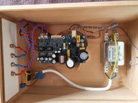
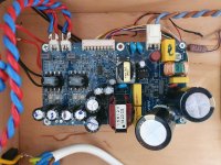
For sale verry good sounding D class amp.I put this some time ago in wood enclosure with some AC filter and conectors.The main capacitor are now supern Nichicon KX.Thie little unit souns superb and the sound is worth every penny.I have try this against some verry expensive amps and the little Anaview was superb in all areas.Im using now tube power amps,so dont use this anymore.Just plug and play.price 150 euro plus shipping or best offer.
Attachments
Hello from France
- By GooseyGander
- Introductions
- 4 Replies
I'm a complete novice at DIY audio and only picked up a soldering iron for the first time a few weeks ago. I am trying to finish a chip amp and need help. I hope this is the place I'm going to find it! Other places I've tried, have, shall we say, been a little snobby and very unhelpful. I have hope in you lot! 🙂
FS Audax tweeters, dome midranges, Philips dome mids & Laspada crossovers
For Sale:
multiple pairs of:
Audax - dome midranges - p/n HD13D37 8 ohms - Soft fabric dome material - used but good to very good working cosmetic condition. All sound good /normal. $ 49/pair. Willing to sell singles.
Phillips - dome midranges - p/n AD 0211 SQ8 8 ohm - soft fabric dome. Rear isolation chamber is part of housing. 8 spoke 'grill' over dome. Made in Belgian. I believed these were used in Bang & Olufsen ( B&O ) speaker systems, maybe in some ADS or Canton or Kirksaeter. $ 49/pair. Some are barely used, others used for short term testing, others look new (NOS). **** 1 - single - left ****
Polydax / Audax tweeters - p/n HD9x8D25 - 8 ohms - soft fabric domes. Rectangular front face / flange. Used, but in good working condition. Sound good. $ 39/pair
Laspada 3-way crossovers - BL-3W-1920. Current model on their website. List for $ 199/pair. 2nd order, 8 ohm with 850 and 3,500 crossover points. asking $ 125/pair. They look unused, but they may have seen some minor use/testing. *** 1 pair left ***
Also have (2) Dayton 12" woofers. Model # ST305-8 - 8 ohms. Like new. Only used for brief testing. 92dB, go down to 25 Hz. $ 75/pair + shipping (they are heavy...).
Message me for pictures or more info.
Will work decent discount if you want multiple items. thanks.
pi speakers, crites spearkers, cornwalls - next build?
Hi everyone,
I am contemplating a new speaker build but am undecided about the direction. I am fairly new to this, especially compared to the caliber present on this forum. Maybe someone could share his or her perspective?
I am looking to build a two or three way design with a 15inch driver plus waveguide. If I was buying new, Klipsch Cornwall Four would be nice. However, this is over budget and would not be as fun.
The speaker should be very efficient and pair well with my diy Firstwatt Amps (M2X & Alpeh J). The listening room will vary depending on speaker size but could go up to 380 square feet (36m2).
My current favourites are
four pi speaker (Pi Speakers, four Pi speaker)
People say good things about the performance as well as the owner! Big plus!
the Crites speakers (
Crites Speaker Style A | Critesspeakers.com)
Are you familiar with either of them or both? If you are familiar with both, how do they differ in sound? Do you have a clear favourite or an alternative suggestion?
Looking for an established, working design.
Your advice will eventuall be repaid with speaker porn.
Thank you for your kind consideration.
All the best
How reliable are bias servo methods?
- By profdc9
- Solid State
- 2 Replies
Bias servo methods that adjust the quiescent current of a class AB stage amplifier typically place a diode or transistor on the heatsink so that the offset voltage between the bases of the output transistors are decreased to oppose the increase in quiescent current with temperature. Are these control loops stable or do they tend to sometimes fail with the quiescent current increasing to high, perhaps damaging levels? I have done some testing with the classic "rubber diode" bias servo methods and it seems like once the quiescent current exceeds a certain value that a runaway effect may occur. Is there a good way to apply additional negative feedback to the bias servo to make the servo loop stable?
FS: beyma TPL-200 tweeters
- By Lowrideris
- Swap Meet
- 3 Replies
used, mint condition, with original boxes.
700 eur.
im located in Lithuania, so European buyer is prefered.
pictures if needed i can be sent in private
700 eur.
im located in Lithuania, so European buyer is prefered.
pictures if needed i can be sent in private
Dayton PS95-8 boombox .. Sub or nah ?
- By pandax
- Full Range
- 4 Replies
Hi guys ! 😉
I was about to start building myself a small boombox, out of 2 Dayton audio PS95 speakers.
Got all the parts, plans, etc.
But i found (alone and sad) a Peerless SDS-P830656 speaker, laying around in my basement from an old project. 😱
And thus, questionning began !
Should i use it in the build ? To help in the lower end ? Or is it more trouble than else ?
And yes, i know, i know, the SDS is no subwoofer.
But it's def better in the low end than the PS95 ... So, hmm, yeah, it might help ?
If so, could anybody help me with the volume and port size ?
I tried winISD, but miserably failed to get anything out of it ...
Regardin amp, i got a small Wondom (Sure) 2*15W.
Thanks y'all ! 🙂
Induction motor knocking sound per rotation
- By 50AE
- The Lounge
- 30 Replies
🙁
Hi folks,
I need help from someone with experience of such issues.
My winding machine induction motor has been knocking annoyingly lately and the knock amplitude seems to increase with ambient temperature, as if some parts become loose with thermal expansion. The knock is a single loud tap feeling being transmitted from the entire motor body to the entire machine
The knock occurs only at a SPECIFIC point of the axle per each revolution which I marked with a pen. It also happens only when the belt is put on and under tension, which gives a hint that the side belt pulling force is needed on the axle. The more the belt is tensed, the more heavy is the knock.
Two engineers already gave me a hint that a possible reason could be some clearance between the pulley and the axle and proposed me to disassemble it, put some anaerobic bearing glue and put the parts back. Sadly I already did it and it didn't fix the problem at all.
Now disassembly of the motor will be quite hard. 🙁
It doesn't make sense for me to be a ball bearing, but what if it is the housing having a clearance. Aluminum has greater expansion coefficient than steel, so it makes sense to check the motor bearing housings. What do you think?
WTB Seas W17ex002
- By EssentialE
- Swap Meet
- 0 Replies
Looking for a pair of Seas w17ex002 drivers. Found a pair along with some morel mdt33 in my closet nib and would like to do a mtm setup. thanks in advance.
NAD C326BEE
- By parote
- Solid State
- 5 Replies
Hi,
I'm aware this isn't really a DIY-related issue, but I thought this forum would be a good place to post because of the technical nature of the issue I'm having.
I had a NAD 3020 for about 30 years until it recently gave up, and after a bit of research decided to replace it with a NAD 326BEE.
I used it with a pair of Audiomaster MLS4 speakers (quite large speakers, around 2 cubic feet) and it was able do drive them perfectly at loud volumes. However the new NAD shuts itself off at over a certain volume (which is much lower than I've heard it go with the old NAD, despite the new one being a more powerful amp). I tested the speakers with my son's quad power amp and surprisingly the exact same thing happens, the amp shuts itself off and flashes a red light at quite a low volume.
One of the problems is that I'm unable to find any technical data on these speakers but I seem to recall that they had an impedance of 8 ohms which should be fine when paired up with the new NAD (it is ok with 4 ohms and above).
I imagine some sort of circuit breaker is being tripped, but why this should be happening is beyond me, as both amps are able to provide more power than the old NAD. Does anyone have any ideas about what may be happening?
Thank you for any help
Suggest an amplifier for my power supply
- Solid State
- 20 Replies
Hi all,
I have been given an old, home made PA amp that was blown in one channel and dodgy in the other. It seems to be a lateral mosfet design, somewhat simpler than the hitachi data sheet design and not really capable of the power supply the chap had fitted.
I have junked then amp boards and am left with two 625VA 42vrms dual secondary transformers (the amp was dual mono) and 20,000uf of capacitance.
This translates to fail voltages of around +- 60v unloaded and around 52v at 10 amp load.
I have been casting around for a suitable power amplifier circuit to use this with. It seems that the voltage is too high for class A designs and so am looking at class AB.
I have read around the subject and cannot decide between mosfet or bjt based output stage amplifiers, it seems more down to the implementation than the underlying technology from what I have been able to gather but would welcome correction or comment on the same.
I of course have seen the Honeybadger sticky and a couple of Apex audio amps but would appreciate more suggestions to research too.
Wanted - Fairchild ul926 jk flip-flops
Hi, I am seeking a couple of ancient Fairchild uL926 rtl jk flip-flops to repair a frequency counter. Hoping someone has some old stock or pulls from an old logic board?? Original part number is uL92629. Anyone?
Importance of OPT bell housing
- By DoktaDave
- Tubes / Valves
- 4 Replies
Hi all. I've just found that I've mis-measured, and my OPT won't fit inside it's transformer can. If I remove one side of the bell housing to make it fit, will that cause any problems (lost sheilding etc)?
4P1L vs 4P1S
- By 316a
- Tubes / Valves
- 4 Replies
I have some 4P1S tubes and got round to running some through the tester as triodes . Compared to 4P1L with -22V grid bias for approx. 35mA anode current ~5mA/V , with 4P1S I need to back off the bias to -27V to stay within dissipation limits and get around 4.2mA/V for a 35mA target current . Anyone running these filament bias are going to cook their 4P1S pretty quickly...
It almost seems as if these are different valves in terms of biasing which is hardly subtle . Has anyone got a (preferably translated) datasheet for the 4P1S or run any triode curves ?
316a
It almost seems as if these are different valves in terms of biasing which is hardly subtle . Has anyone got a (preferably translated) datasheet for the 4P1S or run any triode curves ?
316a
50x50 MEH testbox (snail pace project)
- By SpeakerBob
- Multi-Way
- 49 Replies
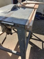
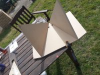
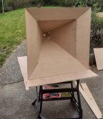
For about 3 years now I've been reading up on Tom D's synergy horns and collecting some drivers / getting my tablesaw sorted with a sledge guide / sledge etc (I found a post by me on here from June2018 saying I'm about to make a sledge 😀 )
I've finally made a test horn. I decided to try a 50x50 horn. Maybe later on I will build something more 90/60 but for now this project is to test the speakers and learn how to get the crossovers done well.
Drivers are BMS 4550 1" CD, with 2x Celestion TF0410MR mids.
I chose Fane Sovereign 10-250 bass drivers but it's been so long now that they have been discontinued 😱 .
For now I'm just concentrating on the tweet / mids....
I used 18mm MDF for testing with plans to use proper plywood when I do final builds.
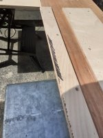
I used Bwaslo's synergy calculator to get the panel sizes, however for my set up I had to work out a bit of extra length for the flare pieces (My saws blade tilts the opposite to Bills so I am removing material from the sizes given by the spreadsheet, whereas Bill is 'adding' material if that makes sense)
The spreadsheet requires you to line up the underside of your workpieces to the 'sacrificial' strip. The way I've chosen means I can line it up from the top which seems easier for me. I marked the sacrificial strip with a sharpie pen before running through to give me a sharp black edge to align to. Once the piece to be mitred is pushed to the edge just enough to hide the black edge I can clamp and be happy its accurate.
Here's a couple of pics of the sledge setup and the cabs. The screws in the flares have been removed and filled / sanded.
I've finally made a test horn. I decided to try a 50x50 horn. Maybe later on I will build something more 90/60 but for now this project is to test the speakers and learn how to get the crossovers done well.
Drivers are BMS 4550 1" CD, with 2x Celestion TF0410MR mids.
I chose Fane Sovereign 10-250 bass drivers but it's been so long now that they have been discontinued 😱 .
For now I'm just concentrating on the tweet / mids....
I used 18mm MDF for testing with plans to use proper plywood when I do final builds.
I used Bwaslo's synergy calculator to get the panel sizes, however for my set up I had to work out a bit of extra length for the flare pieces (My saws blade tilts the opposite to Bills so I am removing material from the sizes given by the spreadsheet, whereas Bill is 'adding' material if that makes sense)
The spreadsheet requires you to line up the underside of your workpieces to the 'sacrificial' strip. The way I've chosen means I can line it up from the top which seems easier for me. I marked the sacrificial strip with a sharpie pen before running through to give me a sharp black edge to align to. Once the piece to be mitred is pushed to the edge just enough to hide the black edge I can clamp and be happy its accurate.
Here's a couple of pics of the sledge setup and the cabs. The screws in the flares have been removed and filled / sanded.
Attachments
EC88 (6DL4) NOS Mullard - any use at all?
- By Gilgy
- Tubes / Valves
- 6 Replies
Just got a couple of these, impulse buy from a real old-fashioned electronics shop, £3 each. Apparently they make good cathode followers, any other use for them? If not for hifi then I was thinking maybe a summing amp for vintage studio fun.
Change password truncates password
- By doz3r
- Forum Problems & Feedback
- 5 Replies
Having been having trouble logging in to the site a couple of times, have had to reset password and login everytime.
It seems like change password silently truncates passwords while login does not. This leads to situations where if you change password to something too long(and thus gets truncated) you cannot login and have to reset the password. This goes unnoticed since changing password does not immediately require you to login with it.
It seems to happen in the 32-64 character range.
DC offset readings
- By Sandm0n
- Solid State
- 8 Replies
Hi All,
I have a Rotel RA-971 mk2, when I measure it's DC offset on the speakers outputs I get 16.8mv for the left channel and 37mv on the right channel but on both the left and right channels my Fluke shows a "-" reading like the reading is in reverse polarity.
1. What is the reason for the reverse polarity reading?
2. How can I "balance" the DC offset readings between the left and right channels?
on the pcb there are only 2 bias adjustment pots
Thanks
Need help identifying: what diode is this?
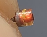
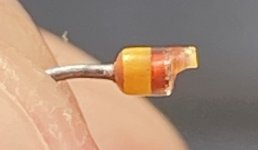
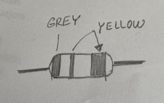
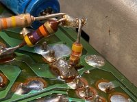
Hi all
this diode has cracked in half in my project Eumig deck. It's not on a diagram, it is a part of a later upgrade. I need help identifying it, pictures are attached. Thank in advance.
this diode has cracked in half in my project Eumig deck. It's not on a diagram, it is a part of a later upgrade. I need help identifying it, pictures are attached. Thank in advance.
Attachments
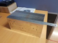
What are my heatsinks good for?
Hi Members,
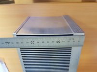
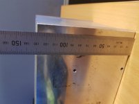
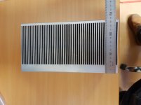
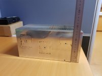
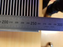
I was wanting to post this in "Solid State" but I thought it may be too general. I've salvaged 6 of the following heatsinks:
260(L)x130(H)x135(D)mm with a ~20mm base plate.
I was hoping to use them for an F5, Alpha Nirvana or something else entirely (fishing for suggestions 😀 class A or A/B). But I'm not sure how they translate to the recommended heatsink size. Both designs are recommending a larger attachment surface area heatsink, but they generally smaller fins and thinner base plates than what I've managed to salvage. Has anyone used something similar for a design like mentioned above?
I don't have a c/w rating unfortunately. Otherwise that may make things easier. I was also contemplating cutting them in roughly half, to turn them into 12 heatsinks...
Thanks for your time.
Attachments

Planning on trying to build Dyi speaker for the first time
Hey all, as the title suggests im currently in the planning phase of trying to build my own portable bluetooth speaker..
my question is, should i pick 4 Ohm speakers or 8...?
The AMP im planning on using is 2.1ch 2x50W+100W, rated for 12-24v operation.
I dont really want to have to build my own battery packs and Im Having a hard time finding a 24v rechargable battery pack.. so planning on using a 12-24v step up transformer aswell just so i can squeez more W out of my amp... (because im guessing the listed Wattage on the amp is at max operating voltage..?)
Im fairly new the while dyi audio scene so any tips regarding anything really is appreciated..!😀
NOS EICO 580VCT @275mA transformers
got them over at Ebay - price here - $40 plus $15.05 medium Priority box
weigh roughly 10lb 2oz


weigh roughly 10lb 2oz
Digitally controlled earth/gound/lift
- By mutedsounds
- Analog Line Level
- 8 Replies
Dear experts,
I am looking for solutions to digitally control the route of the pin1 of XLR/TRS combo inputs to either earth or signal ground or lift. PCB mounted miniature electromechanical relays such as Omron G6 are a solution. But are there valid alternative -cost and area effective- solutions?
Thinking of mosfet-transistors, mosfet-based analog switches such as CD4066 or newer equivalent components or optocouplers, I am actually not sure of the electrical requirements related to the pin1 to earth in line-level connections to be effective as earth to earth shield: maximum Ron, maximum current/voltage, earth noise isolation to control signal/gnd/vcc paths, etc
Would you suggest reference components to do that function?
Tube Operational Amplifier
- Tubes / Valves
- 40 Replies
Do anybody experimented or work around Operational Amplifiers made only with vacuum tubes/valves (No ss at all)?
I have some ideas, but mu brain is open to newer/different ones. What I need is a differential triode/pentode pair wit inverting and noninverting inputs, one or two inverted outputs.
Any suggestion or example is welcomed.
I have some ideas, but mu brain is open to newer/different ones. What I need is a differential triode/pentode pair wit inverting and noninverting inputs, one or two inverted outputs.
Any suggestion or example is welcomed.
Zion, a ready made Phono Stage by the Paradise team
- Vendor's Bazaar
- 188 Replies
We decided to design a new phono stage and make ready made modules availlable. We are also thinking to offer a fitting PSU and maybe a cabinet.
All you have to do is assemble the unit mechanically and do some soldering.
All you have to do is assemble the unit mechanically and do some soldering.
Soldering Aluminum Wire - Help
- By Pano
- Equipment & Tools
- 33 Replies
I'm having no success at all soldering aluminum wire. Maybe someone can help.
The wire is 23 AWG and 32 AWG purchased from Magnepan to repair speaker panels. Included in the kit is a short piece of thick solder, hopefully for aluminum. It seems to have a high melting temperature.
I have read threads here and elsewhere about aluminum soldering, read papers, watched YouTube videos, etc. It seems that it is possible for some to solder it, but no success for me.
The wire is enamel coated so I remove all the insulation with 320 grit sandpaper. Seeing the removal is easy, as the wire changes from amber to a silvery color. I have used contact spray cleaner afterward to clean, or tried without a chemical clean. Getting the supplied solder to tin the soldering iron tip is very difficult, if not impossible. It mostly just beads up. Same for the wire, it will bead up but never wet the aluminum wire. There is flux inside the solder, rather foul smelling and dark.
wiki requests: images, nowiki
- By Mrdrewk
- Forum Problems & Feedback
- 5 Replies
Seems that the [image] tag is broken. I don't want to risk broken links and images over time, so I wanted to upload all the JPGs directly to the wiki. But when I get them in there (upload new file wiki) and link to the image on the page in question, I get a "spinning ball." I believe I saw this bug reported elsewhere. As a "fix" I'm going to use imgur for these images, but like I said: that sort of thing can break over the years.
I also found keywords are getting automatically linked to existing wiki pages. Simply typing the words: introduction, wiki, or system, automatically links over to the corresponding wiki page. This makes my own links, that are actually relevant, get buried. There is a fix for the auto-linking, a tag called <nowiki></nowiki> but that doesn't work either. And it would be annoying to have to comb through my page removing these things anyhow.
thanks![/image]
Input noise calculation
- By SemperFi
- Analog Line Level
- 6 Replies
I think I may be suffering from NCUD (Noise Calculation Understanding Disorder).
When calculating the noise due to input current and source resistance, why do we not use input bias current Ib but only input noise current In which is much less?
Surely the Ib goes thru the Rs and creates a voltage noise...? In an inverted config the feedback Rf is in parallel with Rs but not so in a noninv config.
For instance many opamps have In less than 1pA but Ib up to 1uA. Why ignore Ib for noise calculation?
Thanks for enlighten...
Have you used XMOS interface with a USB3 port on an AMD (Ryzen) motherboard
- By lasercut
- Digital Line Level
- 0 Replies
The source of my DIYinHK multichannel XMOS interface refusing to play unless set to 16bit output in the CP was the USB port, specfically the 3.1 ports on a Ryzen mobo.
These 3.1 ports are a part of the Ryzen CPU's SoC (System on chip), typically (e.g Intel mobos) all the USB controllers are part of the chipset and both AMD and Intel have their own USB3 controller hardware I think (they use different drivers at least).
The interface works fine with USB3 ports on an Intel PC, it also works fine with the chipset based USB2 ports on the same AMD mobo.
I'm curious to figure out where this strange and specific issue comes from, if it's unique to this diyinhk interface and/or this mobo/cpu model or a greater issue with XMOS drivers and the Ryzen CPU's USB controller.
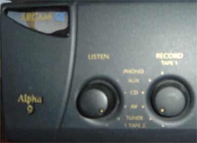
Arcam Alpha 9 amp troubleshooting help needed
- By sif
- Solid State
- 16 Replies
Hello,
Would be grateful for any help...
The listen knob which selects the input (tuner, phono, CD etc) seems to be faulty on my Arcam Alpha 9 amp. It adds static to the sound and sometimes only causes sound to come through one speaker. Only when push and prod it a bit does the sound improve (relatively).. Was wondering if anyone on this forum knows what is causing the problem and whether I can fix it myself. Here's a pic of the offending knob. May be surplus to requirements, but just in case:
[check message length]
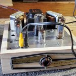
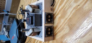
My first tube amplifier
- By redride27
- Tubes / Valves
- 10 Replies
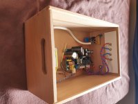
This little guy was built from a reader's digest portable record player. I salvaged what I could and i used some spare capacitors/parts to complete the circuit. (Single ended Dave gillsepie design)
I probably have about 10 dollars into it.
It's built for better output transformers, but I need to save up for those.
I'm not posting this to brag.
I'm posting this to thank everyone on here.
I probably have about 10 dollars into it.
It's built for better output transformers, but I need to save up for those.
I'm not posting this to brag.
I'm posting this to thank everyone on here.
Attachments

Ideas/advice TPA3255 project
I have started my first project, a 3e audio TPA3255 with a douk 400w 48v smps and some bits from audiophonics.fr. The problem I have is doukmall on eBay sent me a the 24v version of the power supply and are being d*cks about correcting their mistake. I’m in the Uk and need to find a cheap compact 48v smps or something like a TPA3251 in Europe to get my project back on track quickly. Any ideas? Thanks in advance.
Audience SX52B discrete op amp
- By Rolox
- Analog Line Level
- 13 Replies
I just ordered a bunch of those "Audience" (Douk Audio, breeze audio, whatever other "Chinese" brand, they're all the same) SX52B op-amps.
Because I also bought a Breeze audio active crossover.
The crossover is a two way and uses a total of five NE5532 in sockets.
So my dumb question is: how can I be sure that the PSU will be able to supply enough current to the 5 op-amps, knowing one op-amp quiescent current is 30mA? Is it just a matter of adding it all? Like, in this case, total quiescent would be 150mA? Then I should just check with the regulators specs if I'm good to go? or is there something that escapes me?
And other question: has anyone here tried those op-amps? I'm usually working with OPA2132 and LM4562, this is my first foray into (cheap) discrete, if I like what cheap discrete do I might invest in something like Sparkos Labs. This is meant as an experiment)
Charger for Li battery, very cheap and dirty way
- By nironiro
- Power Supplies
- 9 Replies
I am not familiar with battery chargers, and need some quick and dirty DIY solution, so any help would be apreciated.
Problem is: charger for Li battery (for photo camera) is dead.
Unfixable, to many SMD components.
Charger specs are: output = 4.2V 200mA
Li battery is 3.7V 740mAh
Can I use charger for mobile phone (output = 4.9V 700mA) for charging that Li battery?
Just to connect + and - pole from mobile chargers to Li battery?
What about third contact on battery, can I ignore it?
Thanks for any suggestion.
Ampere Audio 8k
- By mnhiphop101
- Car Audio
- 11 Replies
This amp came in with a blown ps. I replaced the emitter follower pairs and have good drive on all banks. After installing the fets i powered it up and something popped but I can't figure out what it was and now when I apply power the amp turns on without the remote connected and the fets on one of the banks is heating up. When i pull the fets out of that bank the amp powers up fine and the voltages and drive signal on that bank are normal.
Yamaha cr-3020
- By stofbj
- Solid State
- 29 Replies
Hello everyone,
I have a nice Yamaha cr-3020 which I got in for a service, the owner wanted the power board recapped, Output transistors new heat transfer paste, power amp boards recapped, and new bulbs, and all switches cleaned. All above done without issue. The receiver also had very low volume on FM (before all above work also) I have found where the signal is lost. It's fine where R219 joins to R167 and at the other end of R219 the signal is gone.(just under IC104) So if TR135 is turned on, which is probably is as the Base =0.64 (slightly higher on other voltage meter) it would pull the signal to ground I presume, I have tested the following:
R219= 14.7k
Tr135 = hfe212, uF=687mV, B=0.64, C=0V, E=0V
B=0.64, C=0, E=0V
New c171 & c170 even though they tested fine, I had them out for testing so replaced them.
C143=46pF is fine.
I see TR142 and TR141 look like they detect DC on the output possibly?
I have read the following The base on both are B= -11.76, E=0, C=0V
, as far as I can see E & C are expected at 0V and Base should be -10.44 hard to see on diagram
I checked the voltage with relative to ground on D116 (IS1555) and anode end = -11.71 and cathode= -1.52
What voltage should I expect at the cathode? If we expect TR135 should be in off state, then we need a lower voltage on the base? Am I seeing this right? I'm no expert so could do with some advise please?
Attachments

Audio Note L1 type full amp
- By rclourenco
- Swap Meet
- 0 Replies
To sell a complete built kit of the Audio Note L1 Amplifier clone board, which includes:
- Full Main board totally built (it has worked for some 50 hours)
- The board has all the goodies: Audio Note supply capacitors; Elna Silmic II cathode caps for the driver tubes; Black GAte capacitors + Mills resistors for the power tubes cathodes; Schotky diodes for rectifiers; Audyn True copper signal caps.
- Inlcuded a pair of Lundahl LL1682 Output transfores, already configured for the amp.
- Included the custome Power Transformer (230Vac primary).
- Included slow start board, filaments are connected upn power on, then after 45 seconds, the B+ plate voltage.
- Included a matched quad EL84 Mullard tubes (modern fabrication).
- Included a matched pair of ECF80 Telefunken tubes.
Just had a chassis, some binding posts, a volume pot, and some line-in selector, and you'll gave a fully working super clean and top sounding amplifier.
Selling because I've changed loudspeakers and I need more power.
Total asking price is 750€ + 3% Paypal fee + shipping to be calculated depending the destination.
Drop me a PM if interesteed, I will pack everything very well and double box.
Thanks for your interest.
Regards
Rui L
Portugal
Attachments

IPS Munich - International Parts and Supply 2021
"The Society also announced that the large MOC venue would simultaneously host another show, the IPS Show (International Parts and Supply), a B2B event in which audio manufacturers can directly connect with parts suppliers from around the world."
IPS - HIGH END Society
High End Munich 2021 Is Officially "On"! | Analog Planet
IPS - HIGH END Society
High End Munich 2021 Is Officially "On"! | Analog Planet
Marantz CD5000 - display very dull - help?
- By audio_tony
- Digital Source
- 42 Replies
I have just acquired a Marantz CD5000 with the intent of modifying it. However, upon delivery, the display is very dark. There doesn't appear to be a dimmer option on the remote, so all I can assume is there is a fault.
Can anybody offer any guidance as to where I should start looking? Unfortunately I don't have a schematic, otherwise I could look there first.
I suspect this might be some kind of 'stock' fault with a quick fix.
I can see the diisplay if I cup my hands around it, but only just - however it is working - just not bright enough.
Can anyone help please?
Thanks, Tony.
NOS Harris IRFP9240s, Vgs matched quads and pairs [The Europe Group Buy]
- By Lazybutt
- Group Buys
- 57 Replies
Hello,
Seeing as the group buy organized by Dennis in Canada was a huge success, I am doing a copycat of it for fellow EU DYIers.
I'll be matching using the famous Locky_Z curve tracer.
Will be mainly Vgs matched, but we'll see if we can curve match
Matching at room temperature by default, but depending on the number, I *might* match at a higher, vaguely controlled, temperature of 50 deg C 😉
We're looking at 6€ per part + Paypal + Shipping (price will be confirmed based on import fee)
Expect to receive the parts by year end
I will leave the group buy open for one week, in fear that the stock from the supplier might disappear too quick. No upper limit, but I will only buy the parts if we reach 100 parts (25 quads)
As always, put your name, type and quantity needed.
Update 01/07/2020, here is the final pricing:
Matched pairs: 11€ Sold Out
Matched Quads: 24€ Sold Out
Matched Sextets: 39€ Sold Out
and the matched Septet is available for 45.50€ if you feel like keeping a spare (Edit : Sold Out)
+Packing and Shipping (within EU, it's your choice of tracked letter for 6.50€ or Express insured "Colissimo" for 13€, outside EU, ask by PM)
+Paypal Fee 5% (or 0€ if you "Send Money to Family or Friend" within the EU)
These are late Harris-Intersil parts and they bear the Intersil “i” logo which is different from Infineon Logo), which means they are post 1999 manufacturing date.
The story is: Harris purchased Intersil in 1988
In 1999 Harris spun off the Semiconductor division, so parts manufactured are produced under the Intersil brand. But of course these are the same parts, same manufacturing process, etc)
Distributor is Rochester Elec.
Seeing as the group buy organized by Dennis in Canada was a huge success, I am doing a copycat of it for fellow EU DYIers.
I'll be matching using the famous Locky_Z curve tracer.
Will be mainly Vgs matched, but we'll see if we can curve match
Matching at room temperature by default, but depending on the number, I *might* match at a higher, vaguely controlled, temperature of 50 deg C 😉
We're looking at 6€ per part + Paypal + Shipping (price will be confirmed based on import fee)
Expect to receive the parts by year end
I will leave the group buy open for one week, in fear that the stock from the supplier might disappear too quick. No upper limit, but I will only buy the parts if we reach 100 parts (25 quads)
As always, put your name, type and quantity needed.
Update 01/07/2020, here is the final pricing:
+Packing and Shipping (within EU, it's your choice of tracked letter for 6.50€ or Express insured "Colissimo" for 13€, outside EU, ask by PM)
+Paypal Fee 5% (or 0€ if you "Send Money to Family or Friend" within the EU)
These are late Harris-Intersil parts and they bear the Intersil “i” logo which is different from Infineon Logo), which means they are post 1999 manufacturing date.
The story is: Harris purchased Intersil in 1988
In 1999 Harris spun off the Semiconductor division, so parts manufactured are produced under the Intersil brand. But of course these are the same parts, same manufacturing process, etc)
Distributor is Rochester Elec.
Advice building circuit from schematic only
- By Mrdrewk
- Construction Tips
- 9 Replies
I have some experience with soldering, built a few kits. I'd like to try my hand at a build from a schematic. I have a hard time getting from the electronic component drawing, to where stuff is actually going to go into a board.
Which board? One of those boards where you scratch off the back side to disconnect rows? How to lay things out so it makes sense.
Perfboard, veroboard, scratch board.?
Thought I'd take a stab at the whammy headphone amp.
WHAMMY headphone amplifier - diyAudio Guides

This instructable talks about a wiring planning sheet.
I may be walking myself to an answer here huh. Is there software for this? Other techniques, or YouTube videos that come to mind?
I know there are pcbs available for the whammy. But I could use a headphone amp, I'd like something class A, and don't want to practice on $500 worth of parts. I'd still like to have a thing when I'm done.
Thanks!
Which board? One of those boards where you scratch off the back side to disconnect rows? How to lay things out so it makes sense.
Perfboard, veroboard, scratch board.?
Thought I'd take a stab at the whammy headphone amp.
WHAMMY headphone amplifier - diyAudio Guides
This instructable talks about a wiring planning sheet.
I may be walking myself to an answer here huh. Is there software for this? Other techniques, or YouTube videos that come to mind?
I know there are pcbs available for the whammy. But I could use a headphone amp, I'd like something class A, and don't want to practice on $500 worth of parts. I'd still like to have a thing when I'm done.
Thanks!
Best albums that are only available on cd (or vinyl)
Since I mostly use Qobuz to stream music, have a decent amount of music in DSD, Flac, WAV and a good selection of LP's, but hardly any CD's, I'm curious what great albums that are only available on CD (or vinyl, maybe some D2D) I'm missing out on.
Please share albums you think are great, cannot be found on Tidal, Qobuz, Spotify, etc. and are not for download somewhere.
I'm looking forward to all your contributions🙂
Please share albums you think are great, cannot be found on Tidal, Qobuz, Spotify, etc. and are not for download somewhere.
I'm looking forward to all your contributions🙂
JCricket in Denver aka mark - hello again
- By jcricket
- Introductions
- 8 Replies
Hey Folks,
I am in Denver and registered here quite some time ago, For waht ever reason I settled at AK for quite some time. I had to take a break from there for several years to weather some of lifes storms. Anyway, I am really getting back into my audio hobby and Diy stuff. I have built many tube amps and a few E-Waves.
My next build is going to be a pair of frugal horns. Mydrivers are the Foster fe163's. I'll start a thread in teh speaker forum soon.
So hello again from Denver
Mark
Motorola parts for McIntosh MC2205
It looks like I need to replace a channel in my amplifier. The output transistors appear to be motorola parts numbered
132-133 7439
152 7552
132-134 7426
151 7552
any idea where I could find these or what an appropriate replacement might be?
Thanks
--
Mike
132-133 7439
152 7552
132-134 7426
151 7552
any idea where I could find these or what an appropriate replacement might be?
Thanks
--
Mike
Garrard 401 PSU
- By lt_texan
- Analogue Source
- 31 Replies
[edit: new link as old one is dead]
http://members.rennlist.org/lt_texan/GarrardPowerSupply.pdf
[/edit]
I don’t know if this is the right forum, but here goes:
I’m in the UK and I’ve purchased a Garrard 401 turntable. It is a UK model, so it runs on 240VAC/50Hz.
But it looks like I might need to use this in the US, so I need to convert 115VAC/60 cycles to the UK standard.
I found Dr. Imbabi’s DIY power supply that fits the bill:
http://www.eng.abdn.ac.uk/~eng289/401/401ps.jpg
I figure mains transformers with 115/230 primaries will get me what I want.
Does anyone have experience with this design? I can’t find anything in these archives (except a reference to the above site).
I also don’t understand a couple things, so I’ll toss these out and see if I get a bite:
1. Any ideas on what capacitance should be on each of the “back to back” caps at the output of the LM3886?
2. T1 and T3 rectification looks drawn to be full wave with centre taps to ground, but the voltages calculate as if it is bridge rectification (where CT would not go to ground).
BTW, I know I can convert the 401 to run on 115VAC/60cycles, but I would have to:
1. buy a new motor pulley
2. buy a new strobe lamp
3. buy a new turntable platter (yikes!)
Bet the psu is cheaper, and then I have clean power too.
Thanks much in advance,
Dan
FS: NOS Harris IRFP9241 Matched Pairs
Hello,
I have 4 matched IRFP9241 pairs left for sale
These are NOS Harris parts (with the H logo) which I purchased at Rochester Elec.
They are essentially the same thing as IRFP9240, just with lower max Vds limit (150V instead of 200V)
Curve matching, using Locky_Z curve tracer.
Matching at +/-0.1%
Vds = 20V
2 pairs might be considered a Quasi-Quad = 2 Pairs which are very close to each other at +/-0.25% one pair versus the other
The 2 other pairs look perfect (at +/-0.02% each no kidding ! LOL .. I know this kind of accuracy is meaningless given the measurement accuracy, no continuous mode, blahblah, etc , but I mean they are really close on the curve tracer 😀)
Price is 7€ per pair
+Packing and Shipping (within EU, it's your choice of tracked letter for 6.50€ or Express insured "Colissimo" for 13€, outside EU, ask by PM)
+Paypal Fee 5% (or 0€ if you "Send Money to Family or Friend" within the EU)
Cheers
Fred
How to match Mosfets ?
- Parts
- 4 Replies
Hi,
I apologize if my question is stupid, but I don't have the knowledge to answer it...
A friend of mine asks me if it is possible to measure the MOSFETs in order to get them matched, like we use to do with the Bipolar transistors. And of course, HOW to proceed...
The MOSFETs that he would like to get matched are the IRFP140N.
Thank you very much for your reply,
GU-50 Amp
- By maricopacty
- Tubes / Valves
- 10 Replies
Hello everybody, please take a look at a prototype GU-50 amp ive built.
Attachments
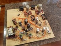
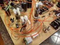
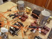
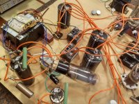
low pass filter for DSD
- Digital Line Level
- 208 Replies
How to calculate a low pass filter for DSD? like other LPF for example if I want a LPF of 50kHz R 32,83 ohms & capacitor 100nF?
Newbie from ontario
- By carlaj
- Introductions
- 5 Replies
Hey folks, Happy Friday.
Looking forward in participating more discussions. The one with immense love on Gadgets.
Looking forward in participating more discussions. The one with immense love on Gadgets.
Hello from an audiophile/tapehead in Ontario, Canada!
- By RyPow
- Introductions
- 5 Replies
Hello everyone! I am an audiophile and tapehead, and am working on building my skills in the repair and restoration of vintage cassette/open reels decks, amplifiers, receivers etc. I knew of these forums previously, but came upon some threads here when I was looking for a replacement Toshiba 2SK170GR JFET used in the playback amplifier of a Nakamichi ZX-9.
I can find my way around a schematic, and a reasonable amount of circuit troubleshooting/diagnosis, but my circuit design and component-level theory definitely needs work! My memories of electric circuits from university (couple of courses) are a bit foggy. Looks like I have found a great place to learn from those with a lot of experience!
Ryan
NAD2240PE
- By nadster2240
- Introductions
- 3 Replies
Hi I’m new here and have been working on a NAD2240PE. Got an issue that maybe someone on this site has experienced before. Right channel is distorted and can’t get the bias set and yes I did desolder the short. It’s plugged into a DBT and the light does not glow. Also when I turn power off sound will still come out of the left channel and distorted out of right channel. Thanks for your help.
Recent F2J - Full-range, plus current source w/ filter realizations...
I recently acquired one of Mr. Pass' FW F2J amps--the F2 with JFET upgrade. I don't think there are many out there, so I was thrilled to find it for use with my Charney Companions (tractrix horns) using the Omega RS-7 drivers. The difference from my (no slouch) SS 110 wpc integrated was positive and immediately noticeable. But, I still thought the mids were overwhelming some musical information in the upper mids to lower high frequencies. The transient snap of the snare wasn't there, and cymbals seemed to be recessed beyond the fundamental--no ring or shimmer to speak of. The upper harmonics that give strings their "bite" were recessed.
So, I revisited Nelson's current source plus filter articles and decided to DIY some switchable filters, which I have now done--3 switches, 4 coils, 4 caps, 4 resistors for each side, including the choice to short the components (not all three at once, of course). The reason I'm writing is because I spent way too much time looking for a simple explanation of the series filter in parallel "notch filter."
Yes, there is a bunch of stuff, including threads here, that talk about the concept, design, etc. But, there is some confusing information (for me, at least)--statements that I never really found good explanations for. I believe I've reasoned them through, so I'm posting both for confirmation and for the benefit of others who may come after me.
How do the RLC components work in a series filter in parallel with the speaker, as opposed to a parallel filter in series with the speaker--in layman's terms?
I had a good idea of how caps act in high-pass and inductors act in low-pass filters. The resistor seemed straightforward, and it was pretty clear to me early on that higher resistor values had opposite effects in the voltage-source vs current-source scenarios. Then, I got hung up on trying to determine the resonance frequency and bandwidth of my filter from the reactive components, and statements to the effect that capacitors become inductors and inductors become capacitors (in the "current source" case) confused me. I wondered, for example, if the resonance frequency of the filter was affected the same way when changing the combination of caps and coils. A literal translation of the statement above would seem to indicate that caps become low-pass components and coils high-pass. I couldn't immediately square that with my intuition or what little I know about electrical theory.
Here is what I never actually read, what I think is correct, and what would have been very useful to read...
In the "voltage source" filter, the signal must pass through at least one of the RLC components because the filter is in series. Therefore, the high-pass function of caps acts to pass high frequencies to the speaker, and vice versa for inductors.
On the other hand, the "current source" filter provides a parallel (alternative) path for the signal to ground, and that signal must pass through all three RLC components.
The resonance frequency of both filters using the same value components is the same. The difference is that the "voltage source" (parallel filter in series) passes the filtered signal to the speaker, while the "current source" (series filter in parallel) passes the filtered signal away from the speaker. The caps and coils still do what they do regarding their frequency effects. It's just that one filter is determining what goes into the speaker, and the other is determining what stays away from the speaker. In that sense, the caps and coils can be thought of as having the opposite effects on frequency.
But, they are not functioning differently in their electrical interactions with the signal. They are simply pointed in opposite directions relative to the speaker.
Am I correct? It occurs to me that the resistor being in series vs parallel with the reactive components may cause them to behave somewhat differently, but my intuition is that the resonance frequency of the filter won't change.
I wasn't sure where to post this, but Mr. Pass seems to come up in most discussions of this stuff, and it is his F2J and work in the "current source" area that led me down this path.
The switchable filters are fun, btw--Dayton Audio caps and resistors with Jantzen coils and Lorlin switches. Even my wife is enjoying the critical listening. 🙂
Louis
Motor speed regulator IC
- By doremi
- Analogue Source
- 3 Replies
A friend brought a Philips 423 turn table which does not turn anymore.
It seems to me that the TDA1059 Motor speed regulator IC is defect. But to get this IC would cost about 30$.
Are there any more common replacment IC available?
In one thread LM317 was suggested, which differs slightly from the TDA1059 - see attachement (copyright Grundig?).
PS
TDA1151 is similar to TDA1059
Attachments
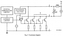
Turntable Lid
- By Spike47
- Analogue Source
- 14 Replies
Hi
I have a Technics Turntable and one of the tongue on the lid has broke, does anyone know what is the best way stick/glue/weld it back on, that is if it can be ! .
Cheers
Spike
I have a Technics Turntable and one of the tongue on the lid has broke, does anyone know what is the best way stick/glue/weld it back on, that is if it can be ! .
Cheers
Spike
Attachments
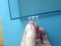
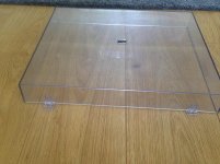
Cut list Optimizer (Web/Free)
- By Napalm44
- Software Tools
- 0 Replies
Great site for when it comes time to start cutting your panels 🙂
Put in what size panels you need, enter the stock you have, and it works out the most efficient layout.
Works with Metric or Imperial
CutList Optimizer
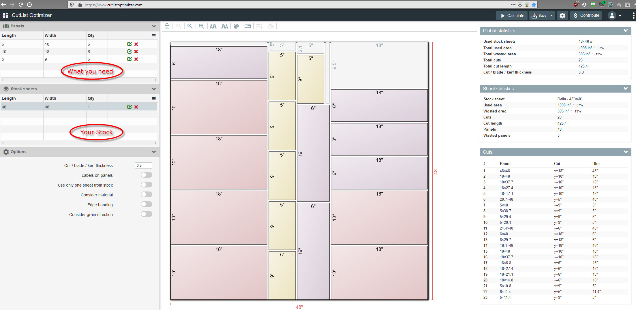

Put in what size panels you need, enter the stock you have, and it works out the most efficient layout.
Works with Metric or Imperial
CutList Optimizer
Load more
Projects by fanatics, for fanatics
Get answers and advice for everyone wanting to learn the art of audio.
Join the Community
507,815
Members
7,889,511
Messages