I have some experience with soldering, built a few kits. I'd like to try my hand at a build from a schematic. I have a hard time getting from the electronic component drawing, to where stuff is actually going to go into a board.
Which board? One of those boards where you scratch off the back side to disconnect rows? How to lay things out so it makes sense.
Perfboard, veroboard, scratch board.?
Thought I'd take a stab at the whammy headphone amp.
WHAMMY headphone amplifier - diyAudio Guides

This instructable talks about a wiring planning sheet.
I may be walking myself to an answer here huh. Is there software for this? Other techniques, or YouTube videos that come to mind?
I know there are pcbs available for the whammy. But I could use a headphone amp, I'd like something class A, and don't want to practice on $500 worth of parts. I'd still like to have a thing when I'm done.
Thanks!
Which board? One of those boards where you scratch off the back side to disconnect rows? How to lay things out so it makes sense.
Perfboard, veroboard, scratch board.?
Thought I'd take a stab at the whammy headphone amp.
WHAMMY headphone amplifier - diyAudio Guides
This instructable talks about a wiring planning sheet.
I may be walking myself to an answer here huh. Is there software for this? Other techniques, or YouTube videos that come to mind?
I know there are pcbs available for the whammy. But I could use a headphone amp, I'd like something class A, and don't want to practice on $500 worth of parts. I'd still like to have a thing when I'm done.
Thanks!
Lots of members use perf board, myself included. Instead of "scratching" a track open simply use a hand held drill bit on the next hole (perforation). A couple of turns with soft hands will eat away the copper track around the hole.
When planning your layout consider that the circuit diagram generally runs input to output from left to right. So that the flow you need on physical layout. Importantly it keeps low level circuits away from high level where interference may occur.
Try to use only dual opamp packages keeping all the circuits for one channel on the same side of the packages and, if you can, line then up in a more or less straight line. This keeps similar functions together (but on opposite sides of the IC for each channel) and makes the progression from in to out logical and easier to debug.
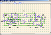
You can still use something like Eagle (free version) or other software to help you layout a circuit that's going on perf board or similar. I've done it many times. Just have in your mind that you are lining everything up as if it were on a perf board.
You might also look at DIY Layout Creator by bancika but the Whammy circuit might be a bit complex for that
You might also look at DIY Layout Creator by bancika but the Whammy circuit might be a bit complex for that
Learn a schematic and pcb layout program, like Kicad or Diptrace. Yes, there is a learning curve, but only once.
Then when you've learned the pcb layout program, it will actually be faster and easier to design and stuff a pcb with
few or no mistakes, than building a circuit on a breadboard and debugging it, which can be difficult and take real time.
If you use a layout program to make a breadboard diagram, you might as well go ahead and make a real board,
it's not much extra work after that. Also, then it's easy to make more copies of the board, even with some changes.
If you lay out one channel, then it takes only a couple of keystrokes (copy and paste) to add a second,
identical channel on the board. Or you can make identical mono pcbs for each channel. Dual mono layouts,
on the same board or not, will work better too. With a layout program, a double sided board is no more work
than a single sided board. In fact, it's usually easier to lay out, with fewer constraints.
Last edited:
Also remember a board has two sides! even through hole components. You don't have to have everything on one side - go 3D. Use the attached leads of resistors etc. to jump other components, use heat shrink if needed
This is perfect, it should get me started. You folks shop at digi-key, or mouser for your stuff? I've usually used mouser, they're okay. Sometimes out of one thing, and 6000 of another that looks the same.
I appreciate the over view. The suggestions on layout programs looks great.
@rayma super helpful. What's the process for "go ahead and make a real board."?? Found a hackaday about "why are you still making pcbs?" and how there's something called a "board house" that will print PCBs from electronic files and send 'em to you. That sounds like what you're talking about? Which board house might you recommend? What kind of costs would I be looking at? When it comes to audio equipment, are PCBs necessarily worse than point-to-point wiring a rats nest? 😉
You are on the correct path but chose a too complex project, doubly so if it´s the first one.I have some experience with soldering, built a few kits. I'd like to try my hand at a build from a schematic. I have a hard time getting from the electronic component drawing, to where stuff is actually going to go into a board.
Which board? One of those boards where you scratch off the back side to disconnect rows? How to lay things out so it makes sense.
Perfboard, veroboard, scratch board.?
Thought I'd take a stab at the whammy headphone amp.
I may be walking myself to an answer here huh. Is there software for this? Other techniques, or YouTube videos that come to mind?
Since you want to make it useful afterwards, build this predesigned/made PCB.
For learning, go step by step.
Choose a project with no more than , say, 15 components, first breadboard it on a solderless push-in type protoboard, then repeat what you did on perfboard, either Veroboard or similar, where parallel tracks are already there and you cut/scratch what you don´t need, or the simplest version, where you have only unconnected copper rings at each hole where you later connect them with copper wire.
And for that, Bancika´s DIY Layout creator is supreme.
Earlier versions (those which work only in Windows) come with user designed examples, which give you ideas.
Practice makes perfect, like with anything else, don´t skip steps.
Ada Fruit make a host of prototyping products, I suggest you start with their mid sized breadboard ($5)

then transfer is a-is, point by point, to their fancy stripboards ($4.50 each)

or the utilitarian ones:TEN for 4.95

for the full line:
Prototyping : Adafruit Industries, Unique & fun DIY electronics and kits
I would have KILLED for such convenient products when I started. 😛
For some ideas and inspiration have a look here Post Pictures of Your Vero Board Designs Here.
veecad along with TinyCad is an excellent option for more complex circuits, allowing you to layout with confidence due to built in error checking against the schematic.
Tony.
veecad along with TinyCad is an excellent option for more complex circuits, allowing you to layout with confidence due to built in error checking against the schematic.
Tony.
Attachments
Last edited:
I'm going to take your guys' advice here and stick with something that's established as a DIYer project, and has PCBs available. I settled on a Pass F5 Turbo builders thread. Thanks for posting, I look forward to more interaction on these forums!
Veroroute...
I can't recommend Veroroute highly enough as layout software for PCBs or perfboard. Its free and incredibly easy to learn. VeroRoute download | SourceForge.net
I can't recommend Veroroute highly enough as layout software for PCBs or perfboard. Its free and incredibly easy to learn. VeroRoute download | SourceForge.net
- Home
- Design & Build
- Construction Tips
- Advice building circuit from schematic only