For about 3 years now I've been reading up on Tom D's synergy horns and collecting some drivers / getting my tablesaw sorted with a sledge guide / sledge etc (I found a post by me on here from June2018 saying I'm about to make a sledge  )
)
I've finally made a test horn. I decided to try a 50x50 horn. Maybe later on I will build something more 90/60 but for now this project is to test the speakers and learn how to get the crossovers done well.
Drivers are BMS 4550 1" CD, with 2x Celestion TF0410MR mids.
I chose Fane Sovereign 10-250 bass drivers but it's been so long now that they have been discontinued .
For now I'm just concentrating on the tweet / mids....
I used 18mm MDF for testing with plans to use proper plywood when I do final builds.
I used Bwaslo's synergy calculator to get the panel sizes, however for my set up I had to work out a bit of extra length for the flare pieces (My saws blade tilts the opposite to Bills so I am removing material from the sizes given by the spreadsheet, whereas Bill is 'adding' material if that makes sense)
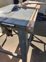
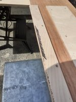
The spreadsheet requires you to line up the underside of your workpieces to the 'sacrificial' strip. The way I've chosen means I can line it up from the top which seems easier for me. I marked the sacrificial strip with a sharpie pen before running through to give me a sharp black edge to align to. Once the piece to be mitred is pushed to the edge just enough to hide the black edge I can clamp and be happy its accurate.
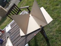
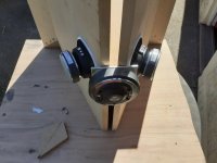
Here's a couple of pics of the sledge setup and the cabs. The screws in the flares have been removed and filled / sanded.
)I've finally made a test horn. I decided to try a 50x50 horn. Maybe later on I will build something more 90/60 but for now this project is to test the speakers and learn how to get the crossovers done well.
Drivers are BMS 4550 1" CD, with 2x Celestion TF0410MR mids.
I chose Fane Sovereign 10-250 bass drivers but it's been so long now that they have been discontinued
. For now I'm just concentrating on the tweet / mids....
I used 18mm MDF for testing with plans to use proper plywood when I do final builds.
I used Bwaslo's synergy calculator to get the panel sizes, however for my set up I had to work out a bit of extra length for the flare pieces (My saws blade tilts the opposite to Bills so I am removing material from the sizes given by the spreadsheet, whereas Bill is 'adding' material if that makes sense)
The spreadsheet requires you to line up the underside of your workpieces to the 'sacrificial' strip. The way I've chosen means I can line it up from the top which seems easier for me. I marked the sacrificial strip with a sharpie pen before running through to give me a sharp black edge to align to. Once the piece to be mitred is pushed to the edge just enough to hide the black edge I can clamp and be happy its accurate.
Here's a couple of pics of the sledge setup and the cabs. The screws in the flares have been removed and filled / sanded.
Attachments
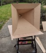
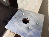
I decided to use ally plate for the CD baffle. I had my old workplace laser cut a plywood template with the 1" hole and the 2x holes for the mounting bolts. I cut the hole in the ally 1st with a 19mm holesaw. The hole ended up around 23mm ! I then bolted the plate to my ply template and used a flush trim router bit to tidy up the ally. Worked out well.
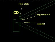
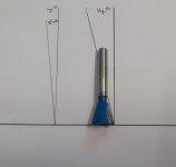
I screwed and epoxied the ally plate to the square opening on the horn then used a flush trim router bit to 'round out' the square. I'm pleased with it but have ordered a 7degree dovetail bit to run round so that there is no flat spot in the tweeters expansion (the BMS drivers exit angle is 14 degrees so it will be matched into the ally plate / mdf)
I screwed and epoxied the ally plate to the square opening on the horn then used a flush trim router bit to 'round out' the square. I'm pleased with it but have ordered a 7degree dovetail bit to run round so that there is no flat spot in the tweeters expansion (the BMS drivers exit angle is 14 degrees so it will be matched into the ally plate / mdf)
Attachments
Last edited:
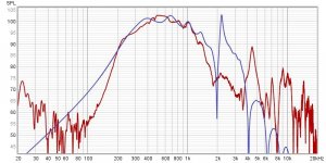
The measured response of the mids matched the hornresp sim fairly well. I have a bit of space between the mid cone and the ports and hornresp suggests that if I minimise this I could move the resonant spike at 4.5k further up and hopefully reduce its intensity.
Attachments
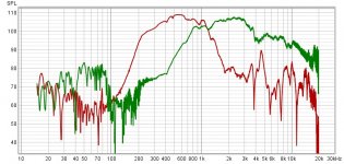
That looks really good. Plenty of response overlap to work with.
Thanks Bill,
I might re measure the front chambers on my mids to see if they match the model.(model done so long ago I'm not sure how close to the real chamber they are. Might explain the difference) The spike around 4.5k is bothering me a bit and I'd like to reduce it acoustically if possible before getting the final xo done.
Rob.
Hi Rob, you could try adding some polyfill in front of the mid to reduce the spike. Looking great so far, the bandwidth of your mids is good. In my build I experimented with volume reducers and found that overall bandwidth increased for the mids at both the low and high end:
https://www.diyaudio.com/forums/multi-way/335062-bm-d446-ph-4220-a.html#post5771061
https://www.diyaudio.com/forums/multi-way/335062-bm-d446-ph-4220-a.html#post5771061
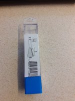
Received my 7 degree router bit today so hopefully will have a smoother transition from the CD to horn tomorrow afternoon. Will be interesting to see if anything changes in the tweeter measurement.
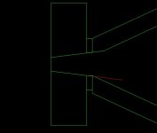
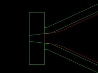
I did a quick sketch on cad to see how different it will look. (actually did it to see if the router bit would go deep enough) This only looks right for the exact middles of the horn panels but does seem smoother.
I did a quick sketch on cad to see how different it will look. (actually did it to see if the router bit would go deep enough) This only looks right for the exact middles of the horn panels but does seem smoother.
Attachments
It's a dovetail cutter. I couldn't find a bearing version with a 7 degree angle so will make a template to bolt to the ally mounting plate, and use the shaft of the bit to follow the template. I'd have preferred one with a bearing.
I did start think about a 16 degree bit to smooth the transition to the 25 (50 overall) flare but decided so little material would be removed that a bit of sandpaper would probably get close enough.
Cheers,
Rob.
I did start think about a 16 degree bit to smooth the transition to the 25 (50 overall) flare but decided so little material would be removed that a bit of sandpaper would probably get close enough.
Cheers,
Rob.
Last edited:
Have you heard of Wealdon Tools? Their router bits are superior, I found this after posting last night, they have some other variations dotted about their router bits section:
Bowl Bevel
Bowl Bevel
Page 8 gives a good profile to match:Detail of how much material will be removed in the corners. Not much but still smooths the flat spot. (red line on bottom panel)
Should get the real thing done this afternoon.
http://www.excelsior-audio.com/Publications/QTWaveguide/QTWaveguide_WhitePaper.pdf
Have you heard of Wealdon Tools? Their router bits are superior, I found this after posting last night, they have some other variations dotted about their router bits section:
Bowl Bevel
They do look good, just a little over my budget for the amount of use they'd get
Page 8 gives a good profile to match:
http://www.excelsior-audio.com/Publications/QTWaveguide/QTWaveguide_WhitePaper.pdf
Thanks Art,
I've read that paper before, will take another look tonight.
Rob
Well a bit of a disaster this afternoon
I set up the new router bit with a template I made. (the 1" hole needed to be a little smaller to allow for where the cutting edge stops away from the shank.)
Set the depth up perfect on a test piece, bolted template to tweeter baffle and routed it out.
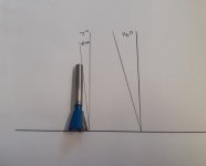
It seems even though the router bit is labelled and boxed as 7 degrees it actually measures 14 degrees. Has made a bit of a mess of the throat.
I've contacted the seller to see if they actually sell a 7 degree bit.
This project on hold for a week now. Will stuff the throat full of car body filler tomorrow to start over when I get the right bit. Luckily it is a test box so not as bad as it could be.
Rob.
I set up the new router bit with a template I made. (the 1" hole needed to be a little smaller to allow for where the cutting edge stops away from the shank.)
Set the depth up perfect on a test piece, bolted template to tweeter baffle and routed it out.
It seems even though the router bit is labelled and boxed as 7 degrees it actually measures 14 degrees. Has made a bit of a mess of the throat.
I've contacted the seller to see if they actually sell a 7 degree bit.
This project on hold for a week now. Will stuff the throat full of car body filler tomorrow to start over when I get the right bit. Luckily it is a test box so not as bad as it could be.
Rob.
Attachments
Hi Art,
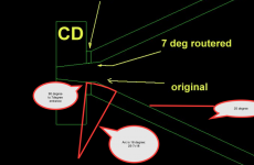
I've just drawn that curve for my horns and its a bit weird due to the straight entrance angle. I thought I should be trying to match my CD's angle at 14 degrees, but this profile doesn't take the exit angle of the driver into account ?
I thought the idea was to have as few discontinuities as possible ?
(Red bit is the Peavey flare profile)
Thanks,
Rob.
Attachments
Rob,1) I thought I should be trying to match my CD's angle at 14 degrees, but this profile doesn't take the exit angle of the driver into account ?
2)I thought the idea was to have as few discontinuities as possible ?
1) You are attempting to blend the 7 degree (1/2 of 14) throat angle to the 25(1/2 of 50) horn wall angle, an 18 degree (25-7) arc radius.
2) Yes, that is true, with the concept of the expanding wave being "normal", (90 degrees) to the horn wall at every point.
You won't find a router with the proper arc radius without making one, and you are attempting to blend a circle to a square. With so little material to remove, a half round file is really the tool to use. Filleting the horn corners to the driver exit diameter is also a good idea.
Art
Attachments
- Status
- This old topic is closed. If you want to reopen this topic, contact a moderator using the "Report Post" button.
- Home
- Loudspeakers
- Multi-Way
- 50x50 MEH testbox (snail pace project)