Feedback on 18Sound 10NDA610 as midrange

Anyone has heard/measured these and can provide some info?

The intended application is from 400/500Hz to about 2kHz, under a TPL-150H, and over dual 10" Beymas.

On paper it looks good: 102+ dB/W from 500 to 2kHz, super low Le of 0.06 mH, smooth impedance curve with a minimum of 6.5 ohm.

Unfortunately there is little published data and scarce comments online that I found. I wish there was some distortion data, and I'm a bit concerned with directivity at 2kHz. Unfortunately they don't make an 8" version, and the 6ND410 seems a bit shy in the lower end of the intended usage range.

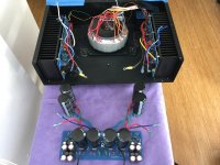
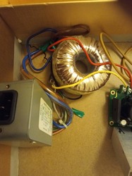
FS: for sale aluminum case for hypex ncore amplifers

For sale aluminum case for ncore hypex amplifiers.

I use one case for nc252mp + nc100hf

Case is made of 3mm alu plates with 10mm front.

It have power off/on on the back, hole for remote, and led in front.

I would like to get 100euro for case with power supply connector but without XLR and binding posts.

Or 135euro for case with power supply connectors and stereo (2 channel ) Cardas CCBP binding posts or 150euro for 3 channel Cardas CCBP binding posts.

I will reuse XLR connectors.

Price is without shipping and money transfer costs (as paypal fee ).

I can send high resolution pictures via mail...

Thanks

Attachments

  • 20200726_101204_copy_1814x1020.jpg
    20200726_101204_copy_1814x1020.jpg
    233.2 KB · Views: 920
  • 20200726_145903_copy_1871x987.jpg
    20200726_145903_copy_1871x987.jpg
    230.6 KB · Views: 909
  • 20200726_145809_copy_1377x1056.jpg
    20200726_145809_copy_1377x1056.jpg
    209.9 KB · Views: 900
  • 20200726_150038_copy_1866x855.jpg
    20200726_150038_copy_1866x855.jpg
    212 KB · Views: 888
  • 20200726_150127_copy_1841x845.jpg
    20200726_150127_copy_1841x845.jpg
    244.7 KB · Views: 891

Understanding INA217 preamp schematics and extending it

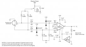
Hey, I have built a preamp from the INA217 datasheet sample schematics (https://www.ti.com/lit/ds/symlink/ina217.pdf, section 8.2, attaching a screenshot to this post).

There is something I don't understand about C1,C2 capacitors.

Why are they so huge? From the hi-pass filter perspective it would make sense to have them 10 times smaller (like 4.7uf, given the following 2.2K resistor). From the phantom power filter perspective there is another 47uf capacitor near the phantom power switch.

The second part I don't understand about the same capacitors is the requirement: «Use non-polar capacitors if phantom power is to be
turned off». What will go wrong if I use polarized capacitors and will switch the phantom power off?

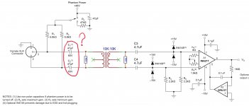
Next thing is that I want to modify that preamp to add an isolation transformer (I have a 10K:10K transformer). Using my mad photoshop skills I've painted the planned schematics (it's not marked on the screenshot, but the phantom power and XLR grounds are planned to be isolated from the grounds after the transformer).

So, the question about the same C1,C2: do I need them given the transformer (which is supposed to block DC from the power supply)? And the second question: is there something fishy with my modification?

Thanks.

Attachments

  • ina217.jpg
    ina217.jpg
    147.5 KB · Views: 370
  • ina217_mod.jpg
    ina217_mod.jpg
    182.7 KB · Views: 366

NNeed advice converting JVC RX-801

file:///C:/Users/donlo/Downloads/hfe_jvc_rx-8010vbk_service(2).pdf

I'm converting this 5 channel AV receiver to a 4 channel bi-amp. It was brain dead (I have a stack of brain dead AV units). I already tested the amplifier boards and they all work. I already designed a control and protection circuit and it's installed and working. I have the power amplifier assembly on the bench now and I'm trying to finalize everything and I'm hung up on one feature of the original unit, which I'd like to either eliminate or integrate into my build.

Look at Page 34, board LVA1022-1. The circuit around Q811 and Q812 seems to control V+ to the differential input stages. It is associated with the 4/8 ohm switch. It looks like it drops V+ to 22 volts.

This doesn't make sense to me. The V+ is much higher than this (around 47 volts on 4 ohm setting). Is this a safety feature? Is it their way of limiting power output? Is this an anti-latchup feature?

I didn't test this feature because the unit was a zombie when I got it. I ripped most of the boards out and hotwired the rest and it works on 8 ohm setting. I didn't have the 4/8 ohm switch wired up but now I do (it controls relays on the power transformer board).

Can I rip this stuff out and replace it with a resistor like the V- diff supply? Do I need to scrub a few volts off to avoid latchup? I will probably leave it in the 4 ohm position (plenty of power) and drive 8 ohm speakers.

Thanks in advance for any ideas, advice, or comments.

Mark Johnson's H9KPXG LV On-Off Switch / Soft Start PCB

Folks:

I'd like to gauge the interest level for Mark Johnson's terrific-looking H9KPXG low voltage on-off switch / soft start board (see PCB: low voltage On-Off switch drives AC mains relay \ includes soft start .. H9KPXG). Because of shipping and customs expenses, this offer is limited to members in North America.

Assuming the boards are no more than $3.00 (US) apiece, postage (without tracking or insurance) is $4.00, the cost of the mailer is $0.20, I figure delivered prices (including PayPal fees) in the US should be no more than the following:

1 PCB = $7.75
2 PCBs = $10.80
3 PCBs = $13.90
4 PCBs = $17.00
5 PCBs = $20.10

Actual prices may be lower as the number of PCBs ordered rises; prices to Canada and Mexico will be slightly higher due to increased postage. You get the idea.

No one is committed. I'm just assessing interest. My plan would be to order the boards in a week or two; shipping to purchasers would occur in less than a month.

Anybody want some?

Regards,
Scott

Basic question

Hi Guys,
Building my first SE hi-fi amp using 12AU7/EL84 combination. Now I've seen different ideas of the location of the volume control, at the input or between the stages, any basic advice out there, or could I use a preset pot on the input to prevent preamp overloading and the "real" volume control between the stages?
Sorry if this shows my ignorance as a newbie, but you guys have previously been very helpfull.

Steve

Needing extra attenuation

so im using the headphone amp whammy as my preamp and have noticed that the thing works and sounds better at gain of 5 or greater, from probably the opamps being more stable. But x5 is too high for my setup and i need to attenuate without changing the gain of the circuit.

The setup of the whammy is as follows-
10k pot>input cap>100kohm to gnd>1k ohm signal/100k ohm to ground>opamp input pin

I changed the ratio of the 1k ohm/100k ohm at the opamp input to 70k/30k to work as an Lpad and the bass became feeble, possibly because the input wants higher value resistor to gnd to set its impedance?

I suppose i could put an input resistor before the pot to attenuate it but if theres no harm then id rather attenuate at the opamp's input to reduce all the preceeding noise.

What should i do?

Successful repair Philips CDR-870

Just a quick post to share how I repaired a Philips CDR-870 cd player/recorder.
It wasn't turning on at all when arrived. Turned out a connector got loose, from Power supply to main board! First time I saw something that simple for DOA.

Then, it would not read discs. Had a look at the drive: wouldn't clamp the disc. Discovered two broken pins which are "joints" of the disc clamp. No way that glue would work - would break again. Also, one of the broken pins had got lost. My luck here was that I had another very similar (almost identical) player: CDR-880. So I could compare how a working unit would be.
I managed to drill two tiny holes in each side and insert and glue in place a bit of hard wire, to make new pins. It worked. Had to make a spacer at the back, because clearances were different, I simply used a blob of hot glue as spacer. So, now it would clamp fine the disc, but still it was failing to read TOC on most CDs! They wouldn't spin! Laser tested out working (digital camera test), was also focussing. Then I tried the old trick: gave a small "impulse" with my finger to the disc at the critical moment when it tried to spin it - and yes, then it would spin and TOC was read most of times!
I was clueless. Decided to swap drives between the two players. Now that was weird! The drive turned out to be fine, my repair was perfect. So the problem was in the Mainboard!
I had a close look, comparing the two mainboards and then it struck me: a discovered a tiny SMD component that had simply broken off and vanished!!!! it was in the circuit are related to motor drive (hall motor), so really important and would explain the disc not spinning well. Now, the problem was to identify the component. Fortunately I had the other good mainboard from the other player, because as the component had vanished, and service manual is NOT complete, I would never have discovered the lost component.
A good search on the net revealed it was a shottky diode.
I had no SMD shottky diodes, so I found a normal shottky diode and managed to solder it in place. Tested and YES, working absolutely fine now!

Another player back to service. It's a pitty these recorders reject most of modern media, though... so I'm selling both.

Attachments

  • DSC_2607_.JPG
    DSC_2607_.JPG
    639.3 KB · Views: 218
  • DSC_2608_.JPG
    DSC_2608_.JPG
    466.9 KB · Views: 219
  • DSC_2610_.JPG
    DSC_2610_.JPG
    570.5 KB · Views: 271
  • DSC_2611_.JPG
    DSC_2611_.JPG
    602.9 KB · Views: 461
  • DSC_2612_.JPG
    DSC_2612_.JPG
    303.5 KB · Views: 220

Audio Precision system one THD vs Power (W)

Hello,

I have a system one with DSP, Analogic Generator and Analyzer : SYS-222, runing with APWin and PCMCIA card. Selftest is OK.

- Is it possible to make a sweep : THD (or SINAD) vs Power (W) ? I can't find anyway to do that...
- What means a white "R" on the top of a graph, sometime on all the graph, some time just in part of it ?

Thanks.

Emmanuel

DIY Carnhill transformers colour for DIYRE Palette

Hello everyone,

I am new here so I would like to apologise preemptively if I'm starting a thread to a subject that might have already been discussed.

I have recently sparked my interest for putting together gear and though my knowledge and experience is still very basic I would like to expand on it.

I purchased a DIYRE palette with 2 colours and was wondering if I could build the 3rd colour myself. It might be stupid or overambitious, but I'm toying with the idea of connecting a Carnhill transformer like the ones used in 1073-s to the empty colour cards sold by DIYRE.

I understand this is a huge transformer that would not fit on a single colour of the palette. I was wondering if I could attach it to a separate blank 500 series PCB (AML-07-091) which would supply power to the transformer while being wired to the blank PCB in the palette.

Has anybody experimented with diy colour boxes using Carnhill transformers. Does anyone have any experience with AML-16-018, and could this be directly wired to the blank colour PCB in the palette?

Any info would be greatly appreciated! Thank you.

Which grade LSK389 to use for hybrid cascode a la Merlin B.

I'd like to make a stereo pair of the hybrid cascode input stage described in MerlinB's "Building High Fidelity Tube Preamps" using a 12AU7 and an LSK389 (matched pair of LSK170 jFETs on a single 6-legged device).

I have no experience with 2SK170, LSK170, etc., and I notice that there are three grades, A, B and C, rated for different Idss. For this application, which grade do I want?

Also, I ran some simulations in LTspice, using a couple of different models for LSK170 and 2SK170. In all cases I get the best results (easiest biasing, lowest predicted THD) using the C grade, which is the one that draws the most current (highest Idss, I think). Strangely, these are slightly cheaper than the A and B grades. Is there a downside to using the C graded part? Any reason to specify an A or B grade? They're expensive, so I'd rather avoid buying multiples to try and see.

Thanks.

What amp do I need to drive this speakers?

Hi!

I just acquired a rather old speaker Cerwin Vega HT-S5 (2 unit) and the subs HT-10D.

Here is the spec:

HT-S5: Power handling 60watts, 8 ohm, 91db. FR: 125hz-20Khz
HT-10D: Power handling 100 watts, 8 ohm, 93 db. FR: 40hz-125hz.

Data were taken from the manufacture.

So I figure the whole system needs (2x60)+100 = 240 watts, adding headroom (from what I read 50%) then it would be around 360 watts.

These speakers have cross over build-in, L/R source > subwoofer > L/R speaker. This is the back of the subs looks like.

I think the HT-10D is 100 watts per channel (showed in the manual)

My questions:
1. How much the sub can take? 100 watts in total or 200 watts in total?
2. Let say the sub take 100/200 watts, how much will be pass on to the left and right speaker?
3. I'm planning to use TDA7498E Kit (160wattx2), will it be okay?

I tested the speaker with TPA3116D2 on mid-volume, just to see if the speaker works ( it works and sounds great), but I think it's under power and I don't want to damage the speaker.

I guess what I'm trying to ask is what would be the best way to bring out this speaker to somewhat its full potential without breaking the bank.

Why does secondary emission show at low current?

Tetrodes and many pentodes show a kink or dip in the anode curves (anode current vs anode voltage) due to secondary emission at around 50 to 70V. This is always most obvious at low anode currents.
Why is it most obvious at low currents?
In beam tetrodes (eg 6V6, 6AQ5) etc, the beaming causes a space charge after the screen dense enough to repel secondary emission electrons back to the anode - that is said to be the idea of beam tetrodes. So it is reasonable to assume that at low anode currents there isn't sufficient post-screen space charge to make this work.
But you see this behaviour in ordinary non-power non-beam pentodes eg 6BH6 (a small signal RF pentode) as well. I would have thought any variation in post-screen space charge would be insignificant compared to the field established by the suppressor grid, even with a pretty open suppressor grid pitch.

Pro restoration for Pioneer RT-707, And vintage Tandberg tape decks needed.

Are there any reel-to-reel enthusiasts located within the NY, NJ, CT, and the tri- state area? I have a Pioneer RT-707 that is in dire need of either a complete restoration. The problem with this deck is that it's not recording, even though meters show that it is, and it also needs to be checked for other problems as well. My Tandberg Model-2, and Model 5 Stereo Quadruple both need the same attention as well.
The reason for picking these areas, is that I'm a firm believer in transporting my pieces by car, rather than risk damaging by shipping them.
If any of you fully restore these or knows of anyone in the area who does, please give me a heads up.
Sincerely, In The 21st. Century

Tenacious 6 - latest 3D Printed Driver vs previous 3D Printed drivers

Hello everyone

I recently released my latest Full Range 3D printed driver, Tenacious 6 on Patreon. This will go out to everyone on December 5th. This is a advancement on the FD51 driver and WF81 woofers before it, and the video goes over how it is performing!

Tenacious 6 VS FD51 & WF81 - 3D Printed Driver Showdown! - YouTube

Driver requires magnets, wire, washers, and glue to be made up. The chassis, cone, spider, surround. All 3D printed components.

Still not the SPL performance you get from a industry driver, but work on that is in full swing now. Just posting here in case any of you are interested in this aspect of things. Effectively trying to create the start of a new section of DIY audio where we can work on developing our own drivers without big tools or factories.

Any questions etc, feel free to ask away!

Paul 🙂

PS hack for Adcom GFA-5400

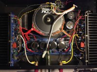
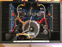
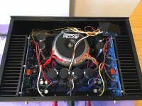
This ingenious hack squeezes in a CLC for the front end PS, while also tripling the PS capacitance of the output stage. PS ripple is so low on the front end that my Fluke meter can't read it, and PS ripple on the output stage is cut to one-third.
I put taller feet to help cooling and dialled the bias up to almost 4W in class A, where it idles on the warmer side.
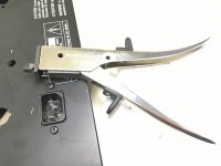
Also I put in multi-turn pots for easy bias and DC offset adjustments, <1% matched source resistors, Kerafol pads, and new electrolytics all around. Used my nibbler to cut a nice rectangular hole for the power entry. Very pleased!

Attachments

  • IMG_1689.jpg
    IMG_1689.jpg
    343.3 KB · Views: 1,024
  • IMG_1391.jpg
    IMG_1391.jpg
    322 KB · Views: 574
  • IMG_1389.jpg
    IMG_1389.jpg
    307.5 KB · Views: 612
  • IMG_1386.jpg
    IMG_1386.jpg
    309.4 KB · Views: 761
  • IMG_1341.jpg
    IMG_1341.jpg
    293.7 KB · Views: 612
  • IMG_1337.jpg
    IMG_1337.jpg
    358.2 KB · Views: 524
  • IMG_0027.jpg
    IMG_0027.jpg
    142.9 KB · Views: 537

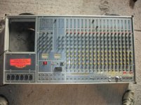
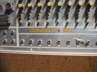
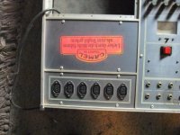
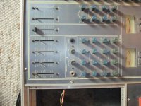
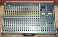
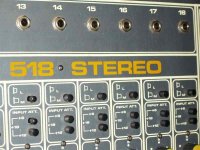
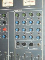
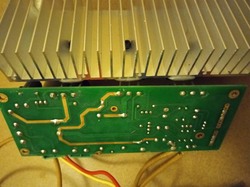
LEM Mixer 518 Stereo - Service-Manual wanted

Who has overtaken this company ? and from where I can order schematics ?
The only URL's I find are this:
LEM Audioersatzteile - gem-lem-service
Generalmusic Promega 2+
But nobody can help there.
Best thanks for an advice in advance.

Attachments

  • DSCF6060.jpg
    DSCF6060.jpg
    995.2 KB · Views: 327
  • DSCF6065.jpg
    DSCF6065.jpg
    1,022.3 KB · Views: 235
  • DSCF6066.jpg
    DSCF6066.jpg
    1,003 KB · Views: 183
  • DSCF6071.jpg
    DSCF6071.jpg
    1,006.9 KB · Views: 327
  • DSCF6072.jpg
    DSCF6072.jpg
    1 MB · Views: 294
  • 195153_kep.jpg
    195153_kep.jpg
    60.7 KB · Views: 141
  • 195154_bemenetek.jpg
    195154_bemenetek.jpg
    47 KB · Views: 131
  • 195155_jobb.jpg
    195155_jobb.jpg
    30.4 KB · Views: 142
  • 195156_monitor_potik.jpg
    195156_monitor_potik.jpg
    43.1 KB · Views: 124
  • 195157_muszerek.jpg
    195157_muszerek.jpg
    37.9 KB · Views: 111

Help with Hood Class A board (mockup fail)

Hi all

I bought a couple (actually 4) of Hood 1969 premade Class A amp boards from ebay. They are premade and have 6 screw terminals on them. They work at about 22-25v AC and I tried to mock up a mono amp with one of them. I should probably point out here the boards would be more than 10w.

This was kind of hard as I needed to heatsink the boards. The boards are no longer on ebay but they are very similar to these ones with different 2 black caps in the middle and pre-adjusted POTs. I used a large aluminium heatsink and a 22-0-22v toroid to try and mock up one channel (click for zoom):


Please excuse the poor soldering - I have just got my station and it's not like a cheap iron. The speaker terminals are not shown used (I needed the wire). The mains block is from a Plasma TV and should provide some filtering as far as I know (I can remove this from the equation).

The result: bad. The amp board simply buzzed the speaker and did not amplify any input signal. I hope the method I used is clear from my pictures.

I have another 3 of these boards if the one I tried is now bad but I can't return it 🙁 Any general advice or did I do something wrong? Experts unite!

Power transformer mA specifications

Dear people,

I have been looking at power transformers for a 100 watt Marshall style build and I am confused about the mA rating of the HT.

What would be the effect of over- or underspeccing the mA rating of the HT?

Classictone 175 0 175 @ 290 mA HT
TAD 173 0 173 @ 300 mA HT
Hammond 175 0 175 @ 420 mA HT

From my understanding the amp will draw the following current:
- preamp tubes 6x 1 mA = 6 mA
- el34's @ 450V = ( 25W/450) x 4 = 222 mA
- screen current 222 mA / 6.5 (screen-to-anode current ratio in datasheet) = 34 mA

Total amp draw 6 + 222 + 34 = 262 mA

Then there is also the RMS ripple current that flows around the transformer and rectifier which I cannot calculate because I do not know the source resistance of the transformer.

Necessary transformer mA is thus 262 mA x unknown ripple current ratio.

Is there something else I am missing in the amps current draw on the transformer?

F5X -- the EUVL Approach

There are 100 ways to skin a cat. I made a promised last year to tell you how I would skin the F5 balanced circuit. In order to help me to focus on this task alone, I have opened a new thread to concentrate information relating to this approach only.

I shall try my best to answer all technical questions related to this approach (only) as much as I can, and as time allows. Please kindly bear with me if I choose to answer certain questions at a later date, e.g. after the prototype build. Please also kindly respect my wish to restrict posts to only those with technical content. If you wish to discuss other approaches, or to comment on personalities, or else, there are already quite a few other threads around for those purposes.

You can find further information about the construction here :
http://www.diyaudio.com/forums/pass-labs/208880-f5x-euvl-approach-build-thread.html


Patrick

Basic stuffing question

Hello. Despite the fact the tech literature treated the subject of stuffing effect in respect of Q of the system I.m pretty much interested about the stuffing effect in the mids and hight into a full range sealed enclosure. Are the mids and hights affected by using stuffing in full range sealed cab please ? In what way ? Can the effects in mid and hights be predicted in respect of material and quantity used please ? I.m not referring at the damping resonances effect. Thanks.

FS: Owon SDS 7201V 100mHz Oscilloscope

FS: Owon SDS 7102V 100mHz Oscilloscope

I have replaced my Owon SDS 7102V 'scope with a Tektronix. The 7102V is 100mHz, 1GSPS, 3.5nS. The auto-set function is very handy. Much easier to use than my Sencore 3100.

Asking price is $225, plus shipping, but happy to consider offers. I'm not sure I have the box any more but do have the manual. Excellent condition, used about 2 years.

GU-50 PP + 10k:16-8-4 Ohm ,20w OPT..what is the best to do?

I Bought this 6AQ5-12au7-12ax7 DIY tubeamp from a seller for 85USD, it's still operational and plays music but not to my liking...maybe because of old caps and components needs to be upgraded. It's 10w pp amp with 4 6aq5 as output...I plant to dismantle it and make use of the bulky power trafo,OPT,5U4G rect and the choke...

Now, the plan i have in mind is to maximize OPT power of 20w. the trafo is japanese made intended for 6AQ5,6bq5 and 6L6. impedance is 10k: 16-8-4ohms terminal. The power trafo is from General transformers with 350vac x 2, 5v,6.3v and still unknown secondary. I only have GU-50 power pentodes and i think overkill for the OPT...so as not to destroy the opt i seek your suggestion of what gu-50 pp schematics is best fo the said opt.

I'm also thinking of GU-50 PP in triode mode.self bias..which will make use of the tube rectifier to lower down the B+ to around 320vdc as seen in the schema.Which is also allowable for triode connection which has 400v max for gu-50 IMHO.
Now, gentlemen i would ask your suggestion.. I'm no tube designer and I'm just an amatuer builder for tuibe amps and i want this amp to stay in my music room so i want the best if possible...TIA

Attachments

  • rear view.jpg
    rear view.jpg
    467.4 KB · Views: 971
  • 6AQ5 PP Int amp.pdf
    6AQ5 PP Int amp.pdf
    213.7 KB · Views: 208
  • inside.jpg
    inside.jpg
    568 KB · Views: 928
  • Side top view.jpg
    Side top view.jpg
    463.3 KB · Views: 894

Reclocking balanced PCM63

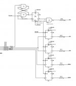
I'm attempting to work out a reclocking schema for a Pass D1 derived DAC. The plan is to adapt the schema proposed on the Audio DAC pages for use with the balanced DAC's. http://members.chello.nl/~m.heijligers/DAChtml/dactop.htm

Everything seems relatively straight forward except how to best to handle inverting the L and R data lines. I was initally considering using the q-bar outputs but came across a thread which suggested there is a delay of roughly 150ps between q and q-bar. I'm not sure how significant this timing difference actually is, but it does make me wonder if I would be better off using XOR gates at the input to the reclocking 74HC175's and use only the q outputs to ensure data is clocked out simultaneously?

any thoughts?

cheers
Paul


note: U5 = 4HC02, U3 = 74HC175

Attachments

  • tent_reclock.jpg
    tent_reclock.jpg
    40 KB · Views: 2,452

Why has noone tried to clone the JAMO D830???

I used to own a pair of these, but I sold them and I really regretted doing that! Id like to get another pair some day, but because Im more into DIY these days, I had a quick search and found noone has tried to clone these legendary speakers. Well there was one dude who was looking into it, but the thread didnt go far. I know the drivers are only available through jamo, but has anyone made a close to original D830?

Problem with 1980's Craig head unit.

Hey,


I have an old Craig head unit that I am bringing back to life. After changing the belt in it, I ran the tape for a few min with no issues- but then it stopped. There seems to be some intermittent issue, but it is "not working" more than it is working.


Checked all solder joints, etc.. Wiggled components, does not seem to make a difference.


Looking for ideas? Or if anyone happens to have a datasheet for the CX-065 motor controller chip? (X-Ref may be M51725L and NTE1300- but the NTE datasheet does not have much information https://www.nteinc.com/specs/1300to1399/pdf/nte1300.pdf)


Schematic linked. Capture — ImgBB


An externally hosted image should be here but it was not working when we last tested it.

Tweaking vacuum tube SPICE model

For info, I found that some SPICE vacuum tube models have to be tweaked in order to work properly in SPICE simulation when a stage drives the grid of the vacuum tube. Marshall Leach is probably the source of the finest vacuum tubes models but even in his text he mentions that that a tweak has to be done. It consists of eliminating the resistor RG1 and the Diode in series between the grid and the cathode of the tube. Leach explains that it is in the model to deal with grid current when the tube is in the positive grid region. On the other hand, it has the effect of loading heavily the driving stage since RG1 is in the 1k range. I don’t know if you guys found that already but I thought that it would help you avoid the pain of finding why your driver stage is performing weirdly and why it reaches the cutoff so fast in an unexpected way.
Cost effective / fun way to add two surround channels for home theater

Hi all,

First off I have spent the last couple hours browsing DiyAudio for the first time, looks like a great community!

I currently have a pretty basic setup with a smart TV / analog out to two Adams A3X studio monitors. I've been toying around with adding a couple of surround channels for fun (in an apartment so I fear I can't add a sub). It seems that the cheapest AVR with preouts is the Denon X3600, and this feels like a bit of overkill because I'd only be using two of its amps.

So I started down the rabbit hole of HDMI audio extractors, found this guy which seems decent but I'd still need volume control. Then of course I started thinking well maybe I should get a DSP in the signal chain for some more fun possibilities (eq/timing). In a previous life I worked in entertainment tech so none of this is particularly scary to me. However I can't seem to wrap my head around the best option for HDMI->DSP->line level analog, I'm willing to go somewhat custom but it's been a while since I've soldered anything.

Also I'm currently using the Android TV build into my X950G, but it sounds like there are still a number of issues with eARC / it might not be supported by these extractors, so I'd be willing to switch to a streaming box if that is the right choice. However, I'm correct that I shouldn't use the S/PDIF out of my TV right? As it doesn't have the bandwidth needed for DD+/Atmos? This all seems crazy to me as someone who used to be in the pro world by the way, why can't I just plug a USB audio interface into my TV and get 12+ channels out? The consumer world is crazy.

Just curious what you'd do if you were me? Maybe the best answer really is drop $800 on an AVR, and a couple of passive speakers for surrounds, and then I get room correction with one button. That doesn't sound like fun though.

measuring freq. response, dynamic range, total harmonic distortion, + signal to noise

Hello,

I have what to some of you might be a really simple question, maybe not.

I built a custom ADC and DAC for the Teensy 4 / Teensy 4.1. I'm considering selling them, but market research shows that people want these measurements. (frequency response, dynamic range, total harmonic distortion, and Signal to noise)

What's the easiest way to perform measurements of my system? Are their any tutorials you are aware of that can help me find these measurements?

Jay

Kenwood DDX5901HD has problem playing Hi-Rez files.

I'm not sure where to post this but here goes:

A while back I donated my Kenwood 5901 to a buddy and he has been happily playing MP3's on it via a USB thumb drive with no problem. Recently he ventured into large FLAC files, some of which are 24-bit, 96KHz and the playback is very strange. It is as if someone reduced the speed of playback to 1/3 or 1/2 speed...and playback continues slowly until the file ends or a new lower bit rate or 8-48 kHz file is selected.
When I used this 5901 I either played small FLAC files or MP'3's and did not notice this problem that I remember.

Anyone have any idea what is going on here?

Thanks for any replies.

Horn with circular flare, Q&D

Being a lazy sod, I have been wondering for while how a horn made from two quarters of a pipe would sound. Finally got around to it today, construction & measurements are very rough & ready, (and bear in mind I'm probably getting cancellation from the rear of the driver), but it looks like a reasonably broad boost is possible:

Attachments

  • h0030.jpg
    h0030.jpg
    24.6 KB · Views: 220
  • h0031.jpg
    h0031.jpg
    25.2 KB · Views: 218
  • h0033.jpg
    h0033.jpg
    23 KB · Views: 229
  • hornpipes.bmp
    hornpipes.bmp
    161.4 KB · Views: 69

Simple HP test amp questions

Because of the corona mess (I can't go home) and high import costs for "exotic"
components ordered from out of the country , I made a small and simple test
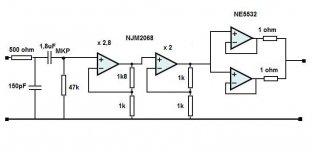
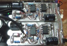
HPamp with the easy to get and very cheap NJM2068 and NE5532.
I had to test the power supply (Elvee's DeNoiser), and protection circuits I had
build with something other than LED's.

Last interesting HPamp design I saw , was with the now discontinued (boo T.I)
LM49600 like in its application information . It's a simplified version of tomchr
(neurochrome)'s HP1 which he isn't sharing . Another is an HPamp with
OPA1622, but this is ridiculously small ( double boo for T.I).

My objective is to have an HP amp that can take my 300 ohm HP's with the tiny
signal from my computer and Mp3 player. They can't handle 300 ohms.
So I made a simpel (boring) one :
After the 1,8uF I measured 7mVdc offset ! (with or without input signal . After the
cap I expected 0mV) . I guess this is the 2068's 150nA input bias current going into
the 47k ? It gets amplified 5,6 times and combined with the 2068 and 5532's offset
to show 37mV at the output. Now I know why nwavguy's O2 has the cap behind the 2068.
Makes a case to lower the 47k to 10k or less , but then the input cap should be
bigger.

Here are my questions:
Am I right that this is the 150nA bias current that creates this 7mV DC offset?
Is there an other easy solution to get that offset down? (no servo).
I'm now using it with an 32 ohm HP :
Is 37mV dc on output dangerous for a small on the ear HP ?
Can I use the NE5532 like used here ( on 2 x 14.6V) with a 32 ohm HP without
damaging it?
Both 2068 and 5532 get hand warm .
The 5532 comsumes about 8mA x 29 V= around 232mW , the LM317/337 deliver 18mA with 7V over them = 126 mW , yet the LM's feel warmer . Weird.

The amp sounds good , like a fuller sound compared to the computer output. But that could be subjectieve.

Attachments

  • Test HPamp.JPG
    Test HPamp.JPG
    21.2 KB · Views: 259
  • DSCF9030.jpg
    DSCF9030.jpg
    114.4 KB · Views: 241

Parallel 6P1P SE Output Transformer Impedance?

Hi new here and also new to tube amps. I got a Nobsound 6P1 Amp a few months ago off Amazon and am looking to mod it a little.

Reading up it seems there are a couple of issues with this amp right out of the box. The first issue is the power transformer primary is rated for 110V, which throws off all the internal voltages when used with the 122V my house has, plus makes everything run hot! I setup a 12V bucking transformer to deal with that issue. But also the first cap after the rectifier is WAY too big at 150uf, so replaced it with a 22uf. Then I rolled in some matched pairs of the Russian 6P1P-EB tubes, and it sounds pretty sweet now for such a cheap amp. Seems the early versions had an undersized rectifier tube as well, mine came with a Russian 5Ц4C in place of the Chinese 5Z4, they both have a 2ma filament but this Russian tube has a higher load rating while keeping the B+ the same.

Anyway, I'm interested in trying a mod to replace the output transformers with something a little better, that can also be setup for UL mode. I would probably set it up with a switch for triode/UL and also want to play with a switchable schade feedback loop while I'm modding it to see what that sounds like. I'm listening through some high efficiency Klipsch KB-15 Icon Bookshelf speakers so it does pretty well for a low watt amp. Given the power supply had some design flaws, I'm not sure the supplied output transformers are an ideal Z anyway + they aren't marked what they even are.

I've attached the original schematic (with issues noted) along with the one with my proposed mods. My question is what impedance transformers will I need? I've read that parallel tube designs like 1/2 the normal rated impedance for SE use. I've also read this tube, and it's US electrical equiv the 6AQ5, like 5K in an SE amp, so does a 2.5K transformer sound right for this use? I'm also open to suggestions for the resistance for the shade loop, most seem to be 180k-220k so I picked something in the middle.

I don't need blasting loud sound, but I don't want to kill the output either. It sounds really sweet with jazzy type music setup in the factory triode mode, but my hope is rock type music will sound punchier in UL mode. I'm not running any preamp or tone controls, just straight out of a Yamaha S300BL CD deck.

I am thinking about a pair of Edcor GXSE10-2.5k at 8ohm as they physically will fit without hanging off the chassis, 10W each should be plenty (I get bigger is better, but this is a sub $300 amp lol), and they have a 40% UL tap to play with. A pair would be less than $80 + shipping.

Again, new to working on tube amps so let me know if I'm off on my thinking here. I'm seriously hooked on how great tube amps sound and have a SEUL KT88 build planned for the future.

Steph

Attachments

  • Nobsound-6P1-schematic-edit-Stephe.gif
    Nobsound-6P1-schematic-edit-Stephe.gif
    82.3 KB · Views: 1,021
  • Nobsound-6P1-schematic-edit-Stephe-2.gif
    Nobsound-6P1-schematic-edit-Stephe-2.gif
    40 KB · Views: 1,489

PPI PCX1500

Amp powers up and plays audio but very distorted audio and when a load is put across the speaker terminals as far as a dummy load or a test speaker the amp will start drawing excessive current and the test speaker will start screeching .


Any ideas on what to check ?

The amp is producing both + - 15 volts on the opamps and +- 40 volts of rail at idle

Attachments

  • FFF208BD-E76D-4E90-BF52-F826A1D2FD96.jpg
    FFF208BD-E76D-4E90-BF52-F826A1D2FD96.jpg
    1.1 MB · Views: 116
  • BC9CF33C-358B-47AC-9B9D-3C1C38D8923A.jpg
    BC9CF33C-358B-47AC-9B9D-3C1C38D8923A.jpg
    1.1 MB · Views: 141

Turntable hum pickup in right channel only

I have the following setup:

Thorens TD-160 Super turntable
Mayware Formula 4 arm
Denon DL103 pickup
Lundahl LL1678 step-up transformers
American Audio - Audio Genie Pro phono preamplifier (temporary solution for measurement)
Analog dual channel oscilloscope (battery operated)

The issue is some hum in the right channel. If I swap the R and L cables coming from the turntable, the hum moves to the other channel. There is a grounding wire attached to the arm, this wire is not connected to the chassis. The chassis is connected to the mains earth though the IEC mains socket earth pin. The other end of the grounding wire is attached to the earth screw on the phono preamplifier.
I checked the continuity between the arm wires and the earth wire (no connectivity) and between the R and L GND (no conn). How is the R channel is different from the L channel so that it picks up some hum and the L channel does not? (The motor generates some more hum in both channels, but the hum in the R channel is present even with the motor off).
Sorry I can't give any quantitative data because my measuring phono preamplifier has variable gain. In my case the hum peak-to-peak is about 4x the peak-to-peak noise in the R channel. The L channel noise is the same but no hum.

What is your fave podcast

Me, hands down, Dennis Miller -- last week he interviewed Mike Rowe "Dirty Jobs" fame. Do not listen to this unless you have the headphones on.

My son was flying from SFO to EWR listening to the Miller interview of Orson Bean two years ago (sadly Bean RIP last year) and he, headphones and all was laughing so hard his wife was punching him to shut up during the flight!)

Otherwise, for me it's a bunch of biz pods -- "Big Brains" from UChicago, "Masters in Business" from Bloomberg.

Audio loopback - THD & Signal/Noise ratio

I'm looking for some way to corroborate some stuff I am working on.

If I:

- plug a loopback cable between Line out and Line in

- Play a 1kHz tone (at 48kS/s)

- Record that tone (for say a second)

- Run Fourier Transform over that data

- Adjust the playback and capture gains until the optimum point is found (just below clipping is detected)

Is there any examples of what these spectrums should look?

And then if:

- I remove the the 1kHz tone from the data.

- Remove the subsonic/ultrasonic components (I assume there is a standard weighting that could be applied here)

Then what is left over is a measure of THD+Noise?

What sort of figures would you expect to see for THD+Noise on a nasty audio CODEC and a good audio CODEC?

In my current experiments I'm getting figures over about 0.005% on a laptop and 0.01% on a desktop. Do those numbers sound about right?

Extra tuned box to cancel standing waves in speaker box

Ok, so this is about standing waves (top to bottom) in tower speakers, a common problem, and can easily be seen as a bump on the impedance curve if the woofer is mounted close to the end.
I have tried killing this with internal damping/stuffing, and it works ok, but I have seen people building towers with a small resonator (separate box and port in to the main enclosure) in the bottom to cancel these standing waves, and would be interested in trying this. I'm modifying some towers that actually has a box for sand filling in the bottom and woofer at the top, so they would be a perfect candidate to try this.

Hobby Hifi (Germany) apparently had an article about it, but I have not been able to find any info on the web.
I would like to see how it's calculated and practical examples with measurements, how to fine tune etc would be even better. Should be something out there..?
Hope somebody can share links? Or experiences?

Good closed cab for 6" speaker and low wattage tube amplifier

Hi guys,

does anybody now of a design of a good sounding 6" guitar cab/amp for playing in the living room?

I have a small low wattage (0.5W) marshall style tube amp that would be perfect for that. Through a 12" speaker it sounds incredible. Through a 6" jensen alnico it sounds more bell like, with piercing highs and no low end.

Are there any tricks (like venting, bass reflex,...) that could be used to tame the highs of a 6" speaker and give it more bass response?

I find amazing how there are tiny bluetooth speakers with tons of bass, but not a single small-ish tube amp. If one neglects speaker distortion, would that be an option?

I would like to learn a bit more about acoustics to give it a try. Any suggestion where to start?

CAOW1 2-Way / Dennis Murphy Design

I've tried to do my due diligence in the threads before posting but some external links have expired and I'm finding more about the brother speaker MBOW1 (and bit about the Salk Song Surrounds). Not so much on straight CAOW1 build experiences.

I was curious to know if anyone currently uses the CAOW1 or has built according to the cab schematics on Dennis Murphy's site. Had seen a picture of a now sold build featuring the SEAS ER15RLY in place of the C15RLY (identically spec'd from what I can see).

In any case, just trying to gather some real-world listening intel/impressions od the CAOW1. I know Dennis' crossovers are legendary. Was a little thrown by audiosciencerev's measurements on the MBOW1.

I know nothing as Buddha might say.
M
  • Like
Reactions: szczemirek

How to apply separate pot for bass speaker driver

My speakers are bi-wire able.
Upper section consists 2 midrange drivers and tweeter.
Bottom section just bass driver.
I would like the bass driver to be more flexible in addition to whole speaker volume regulation from amplifier.
That means, while low level listening it can be fully engaged, when volume rises, I want to reduce its output to my liking. And I would like to do it on the way from speakers terminals of amplifier to the speaker post.
The best one volume pot for both right and left speakers. Is that possible?
Thank you

How do I start?

Forgive me if this have been asked before, a quick search didn't reveal what I was looking for.

Basically I would like to hear your ideas on how to educate myself, so that I might be able to understand what I'm doing, when I eventually dare to build a DIY amplifier.

I have no ambition of getting an engineer worthy degree of sorts, I just want to be able to follow a DIY guide for Nelson Pass designs, and be able to trouble shoot and understand what the significance of the components are.

So the baseline is pretty low, high-school level understanding of electricity, and due to my former employment I understand some of the speaker/amplifier specific terms - but not nearly enough to just go ahead and build anything yet.

I have access to O'reilly, so hopefully some of the books that might prove valuable 🙂

Beyma 15MI100 - TSP confusion

Hello,
I am building a system using Beyma 15MI100 (and some other components).
The pdf datasheet is showing VAS = 166liters and fs = 48Hz.
Loudspeakerdatabase.com is showing 264 litres / 37Hz.
Who is right? Can we trust loudspeakerdatabase.com in any way? What about their built-in "simulate this driver in a closed box" online feature (as I am going to use it in a closed box ~93liters)? Is loudspeakerdatabase any good site?
Also, in what way do the stock TSP parameters change, if the 15" has been used already ~200h at medium to high power in a BR cabinet?


(Please no comments here about the early rolloff, the low QTc and the high corner frequency. This is intended for the the midbass way. And gentle but sophisticated DSP crossover will align both 2 x 15" and 2 x 18" to have almost linear acoustic response down to 20Hz. The 2 x 18" will also be closed box, but bigger.
I will open another thread about the build as soon as I have designed the parameters right. There you can comment and critisize my calculations and intended system build. But first I need reliable TSP parameters for 15MI100.)
Thanks!

Nakamichi ta-3a turns off completely. Dead no power all of a sudden

Have ta-3a . Worked fine for years.
Now I have sudden loss of power
After listening to music for a little it shuts off completely. No power button light (neither red nor green)
I use remote with this amp. The very first time this happened it switched from green light to orange light ( orange is stand by or dc relay protection mode). I could power it back on with remote. I believe it just turned off

Second and 3rd times it just dies completely.
I can manually turn it back on it will play for a min and turns off completely (no lights at all)

I've read somewhere about 22k resistors that go bad on nakamichi ta-3a

But the symptoms of those is that an amp goes to protection mode.

Could it be those resistors or it's something else

Sansui G4700, random fault, help!

Hello people. I am repairing a Sansui G4700 receiver, only one channel has a random fault, it only amplifies the positive part of the signal, this problem appears and disappears by itself. It is not a problem with the preamplifier, only in the power stage. The funny thing is that it can be working perfectly for a week or more, and suddenly the fault appears, lasts a few minutes and then disappears. Check all the welds, solve the ones that seemed suspicious, change some components affected by glue, but the problem remains. It is not false contact. The duration of the problem, does not allow me to make many measurements, in a short time it normalizes. I suspect some transistor, for the moment, I decided to exchange a group of transistors with the channel that works well and leave it in test to see if the fault persists or moves to the other channel. Any idea or suggestion is welcome.
Satori mw16p vs Vifa NE180W

Hi friends!.
Looking opinions for my next build. It will be a slim 2.5 way floorstander.
The tweeter will be the satori ring radiator and I want to debate on the Satori mw16p vs Vifa NE180W drivers.
I know that satori is easier to work with and has better distortion profiles, but I've read many people saying that vifa ne180w actually sounds better.
Also the vifa ne180w is about 20 dollars cheaper per unit.

4P1L Filament Supply Confusion

I'm confused about the proper filament supply design for the 4P1L, or any DH tube, I suppose.

I've seen PSE schematics that show each channel (2 tubes) being heated by the same filament supply.

Yet, I've read posts elsewhere that claim that DH tubes always need to be heated using a separate filament supply for each individual tube, regardless of whether the topology is SE, PSE, PP or PPP.

Which is correct and does it apply under all circumstances? In other words:

Do different topologies (SE, PSE, PP, PPP) affect what is allowable?

Do different bias schemes (cathode, fixed, filament) affect what is allowable?

Pass Aleph 5c amplifier - hum on both channels

Good day peeps

I have a Pass Aleph 5c kit amplifier on the bench of a friend.

It has an unacceptable high hum on the speaker outputs.

There is virtually zero DC offset. Grounding was done according to all the tried and tested theories (including referencing to Douglas Selfs writings).

The hum is present when the inputs are shorted and also when the ground is lifted.

Any pointers...?

What makes a good pass transistor in a serie regulator

About ripple rejection what BJT parameters are important.
In a topology, i am working on, Early voltage makes a lot of différence.
I understand there à feed through effect coming from the collector dynamic resistance related to Early voltage.
I think a good pass BJT should have hight VAF.
Low collector capacitance matters too.
What do you think.

12AU7 tube amplifier powered by batteries

Hi, for some time I was playing with the idea of building a portable speaker with tubes. I normally build guitar amplifier, but this time I gave this a shot.
F9CAL4DKDX3PNKW.jpg


FWLFJPSKDX3PNKV.jpg


I posted the whole design and build process over instructables How to Build a Portable Bluetooth Tube Amplifier : 14 Steps (with Pictures) - Instructables, maybe you find it interesting.

And a picture from the interior:
FNJDETFKEJYQPBW.jpg


For a low cost tube amplifier build it turned out pretty nice.
Cheers.

Schneider TA 4000 sound issue.

Hi,


I have a problem with my Schneider TA 4000, sound still coming out of the right channel when volume is at zero. The issue is not in the balance or volmue potentiometers and I have not been able to track down the service manual. Any ideas on what is happening, is there a simple pot to tweek, thanks?


PS How do folks get the boards so clean, is there a special super small cotton bud that does fall apart?

FS: scan speak 21W8555-01

Hi
Would like to sell scan speak 21W8555-01
I have 4 of them

Thay have not been used for a while, have been laying in the closet with no use so I would like to sell them.

Two of those I have buy new and two used.

On the picture are those that I have buy new.
The other two I can post pictures in a couple days.

Thay are all working great.

I would like to get 150euro for those on picture ( 2 x 21W8555-01 ).
Or 200euro for all 4 x 21W8555-01
+ shipping costs and pay pall fee if applied...

I think that shipping inside EU is only reasonable.


Thanks

Attachments

  • 20201007_185956_copy_1814x882.jpg
    20201007_185956_copy_1814x882.jpg
    185.9 KB · Views: 331
  • 20201007_190052_copy_1814x882.jpg
    20201007_190052_copy_1814x882.jpg
    231.2 KB · Views: 327
  • 20201007_191623_copy_1716x952.jpg
    20201007_191623_copy_1716x952.jpg
    245.9 KB · Views: 322
  • 20201007_191701_copy_1814x882.jpg
    20201007_191701_copy_1814x882.jpg
    201.7 KB · Views: 324
  • 20201007_191724_copy_1814x882.jpg
    20201007_191724_copy_1814x882.jpg
    232.8 KB · Views: 322

The Northern Pikes

Thought I'd share something I completed a little while ago. This one was whipped up over a few weekend and then a few more weekends since spring, but the effort has been worth it!

The Northern Pikes were a band from my home town, they were a big deal when I was growing up. Highly recommend giving a listen if you're into 90's rock.

It's an AMT3-4 on top, a Wavecor WF120BD03 in the middle, and a Vifa M26WR09-08 on the bottom. Around back is a CSS APR-12. The result is a fantastic combination with exceptional clarity.

The baffle is African Mahogany with Maple accent, and maple veneer on the sides. It was my first time veneering, and learned some valuable lessons. There is some cracking in the veneer unfortunately, as I learned that wood glue iron on mothod is best used on paper backed only, so next time I am using contact cement instead.

The phone photo unfortunately shows a lot more red than there is in reality, the second up-close photo is more proper colour.

attachment.php

Attachments

  • y774lmi4zz33.jpg
    y774lmi4zz33.jpg
    395.2 KB · Views: 429

Distortion-measurment at high levels

Hi.

I´m building a small PA-ish speaker with 2x6" and driver+horn.
(Posting here and not in PA, as I hope for relevant input here)

Crossover is 1.6Khz, 4th order, fully active. 120Vpp amp for mid-basses.

Sound is OK, at moderate levels, but at high levels it becomes "unpleasant".
Amp is not clipping as far as I can see.

The drivers are high-power units with 2"voicecoil and rating of 200/400W pr unit. 91dB/W.

I'm trying to measure distortion with my (cheap) measuring mic and and STEPS/ARTA.

What level of distortion shall I expect? at moderate levels I get around 0.5% and at high levels I get 2-5%. At very high levels I get peaks of 20% distortion at some frequencies.

I will try to capture some waveform and post here.

All inputs are welcome 🙂

Kind regards TroelsM

Latest project 100 watt biplolar amp based on 1980's Maplin disco amplifier

I have taken the 1980's Maplin 225WRMS disco amplifier and brought it up to date with modern transistors and a better circuit.
Constant current source on front end. Better front end decoupling.
Decreased power output to 100 watts RMS.
Output transistors are MJ15003/4.
An externally hosted image should be here but it was not working when we last tested it.
Projects by fanatics, for fanatics
Get answers and advice for everyone wanting to learn the art of audio.
Join the Community
507,765
Members
7,887,482
Messages

Filter

Forum Statistics

Threads
406,178
Messages
7,887,482
Members
507,765
Latest member
aleminx