I'm attempting to work out a reclocking schema for a Pass D1 derived DAC. The plan is to adapt the schema proposed on the Audio DAC pages for use with the balanced DAC's. http://members.chello.nl/~m.heijligers/DAChtml/dactop.htm
Everything seems relatively straight forward except how to best to handle inverting the L and R data lines. I was initally considering using the q-bar outputs but came across a thread which suggested there is a delay of roughly 150ps between q and q-bar. I'm not sure how significant this timing difference actually is, but it does make me wonder if I would be better off using XOR gates at the input to the reclocking 74HC175's and use only the q outputs to ensure data is clocked out simultaneously?
any thoughts?
cheers
Paul
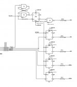
note: U5 = 4HC02, U3 = 74HC175
Everything seems relatively straight forward except how to best to handle inverting the L and R data lines. I was initally considering using the q-bar outputs but came across a thread which suggested there is a delay of roughly 150ps between q and q-bar. I'm not sure how significant this timing difference actually is, but it does make me wonder if I would be better off using XOR gates at the input to the reclocking 74HC175's and use only the q outputs to ensure data is clocked out simultaneously?
any thoughts?
cheers
Paul
note: U5 = 4HC02, U3 = 74HC175
Attachments
150pS skew would not be an issue in this location. What is important is the bit clock arrives sufficiently later (usually half to one master clock cycle later) to clock in the data bits.
The LE signal at the PCM63 is the one to be very nice to. Double buffering (deeper fifo) has sounded better to me. If the DF is an "older" one with a deglitch output, usually one master clock earlier and inverted to the LE signal, re-re-re-reclock it to get a deeper fifo and better jitter rejection. If you have a differential clock, you can ping-pong the d flops to get double the number of stages in at the same time delay.
Good to see interest in the classic PCM63. It can be very enjoyable, involving, musical.
Share and Enjoy,
WMS
WMS,
Thanks for the advice. I wasn't sure if the critical point for timing was loading data into the DAC. Using q-bar should simplify things quite a bit. I'll try getting the modified Tent schema working before delving into re-re-reclocking 😉
I realise I'm going to be better off with picogates, but if I stick with 175's I seem to have two options:
a) run LE thru one '175 and data thru a second.
b) use a '175 located close to each pair of pcm63 and reclock data and LE at this point.
I'm tempted to use option b as this allows '175s to be located very close to the DAC's will allow trace lenghts to be better matched.
DF is SM5842APT, and the clock is a Tent VCXO.
cheers
Paul
Attached is an "in progress" schematic. It's based on the Pass D1 front end with the following changes:
a) Jocko Homo's spdif input replacing everything up to the CS8412/4
b) D1 VCXO/PLL modified to work with the Tent Labs VCXO
c) Audio DAC project reclocking schema modified for balanced operation, replacing the XOR gates used in the D1.
d) Provision for WMS loop filter mod 😉
Most component values, power supply and other details are still missing.
Attachments
Hit post a little too quickly...
I'm a bit puzzled about how to best handle the series termination on the lines from the DF to 175's and the LE lines from 175 to dacs. I've read somewhere that it's best to split the lines at the source and add series termination to each of the lines. This is what I've done on the LE outputs. Is this worth doing on the lines from DF -> 175's and should I also use this strategy on the CLK line to the individual dacs?
cheers
Paul
spzzzzkt said:Attached is an "in progress" schematic. It's based on the Pass D1 front end with the following changes:
a) Jocko Homo's spdif input replacing everything up to the CS8412/4
b) D1 VCXO/PLL modified to work with the Tent Labs VCXO
c) Audio DAC project reclocking schema modified for balanced operation, replacing the XOR gates used in the D1.
d) Provision for WMS loop filter mod 😉
Most component values, power supply and other details are still missing.
please get rid of HC4046 or derivatives, these are horribly noisy.........
then keep up the good work !
best
Hi Gudio,
Thanks for the advice - I'll look at some alternatives for the PLL. At this rate I'm in danger of ending up being a direct lift of the Audio DAC front end - not that would be a bad thing given it's pedigree 😉
cheers
Paul
Thanks for the advice - I'll look at some alternatives for the PLL. At this rate I'm in danger of ending up being a direct lift of the Audio DAC front end - not that would be a bad thing given it's pedigree 😉
cheers
Paul
spzzzzkt said:Hi Gudio,
Thanks for the advice - I'll look at some alternatives for the PLL. At this rate I'm in danger of ending up being a direct lift of the Audio DAC front end - not that would be a bad thing given it's pedigree 😉
cheers
Paul
Hi Paul
Get the point, we have saying like " beter goed gestolen dan slecht bedacht ", you are free to use the design for your own purpose
cheers
Hi Guido,
Thanks for clarifying the situation on reuse of the circuit. I'm also looking at doing something like Jos Van Eijndhoven's pic based pll. http://www.eijndhoven.net/jos/dac2/index.html
Obviously that is significantly more diy...
cheers
Paul
Thanks for clarifying the situation on reuse of the circuit. I'm also looking at doing something like Jos Van Eijndhoven's pic based pll. http://www.eijndhoven.net/jos/dac2/index.html
Obviously that is significantly more diy...
cheers
Paul
spzzzzkt said:Hi Guido,
Thanks for clarifying the situation on reuse of the circuit. I'm also looking at doing something like Jos Van Eijndhoven's pic based pll. http://www.eijndhoven.net/jos/dac2/index.html
Obviously that is significantly more diy...
cheers
Paul
Hi Paul
Ye, that is. I know Jos very well. he is not giving away the code for that PLL as it took a long time to design that thing
best
Guido,
just wondering which smd ferrite beads you recommend for the chip supplies? I couldn't find any reference to the specs of the ferrites used in the Tent DAC.
I'm getting close to a solution for the PLL, so once that is sorted I'll get back to the reclocking schematics....
cheers
Paul
just wondering which smd ferrite beads you recommend for the chip supplies? I couldn't find any reference to the specs of the ferrites used in the Tent DAC.
I'm getting close to a solution for the PLL, so once that is sorted I'll get back to the reclocking schematics....
cheers
Paul
Finally getting somewhere with the software pll. At very least have something will lock to the recovered clock signal, but needs some substantial refinement before I'd consider it to be really usable. Currently have the pll rigged into the D1V3 for testing and seems to be stable once it achieves lock (about 3 minutes).
Slowly progressing towards something relatively usable with the software PLL. I'm getting an effective loop frequency of around 0.7Hz, which is the cut over point to a "loose" low gain mode and should be achieving something at least marginally better (lower) than that. Not sure that I'm getting down to Joseph K's 0.1hz loop frequency yet however.
Listening to the setup in the D1V3 it seems that there is a clear improvement over the D1 derived PLL/VCXO I had previously used, and had drawn into the above schematic. Overall the software controlled PLL seems to be better balanced tonally, and has better resolution of detail. Fairly promising for a test setup running of 7805 regs and a relatively noisy voltage ref.
Listening to the setup in the D1V3 it seems that there is a clear improvement over the D1 derived PLL/VCXO I had previously used, and had drawn into the above schematic. Overall the software controlled PLL seems to be better balanced tonally, and has better resolution of detail. Fairly promising for a test setup running of 7805 regs and a relatively noisy voltage ref.
I have one more adapter board to fab on strip board to complete a test build of the Tent/Audio DAC reclocking schema piggy backing on the D1V3 for the moment. I've tested one channel and only had to perform some minor bug squashing to get that working correctly, the second adapter is 2/3 done after making a couple of errors in laying that out.
The adapter boards are used to plug a 74HC175 in place of the existing 74HC86's and allow reclocking of the LE and Data lines. The PCM64 are being fed directly from the VCXO/PLL via the RS flip-flop portion of the T/AD circuit. I've only been able to listen to one channel of the DAC so can't really make any comment on how it sounds. There are some positive signs already - the LE waveform looks much cleaner with less ringing. I'm looking forward to hearing how it sounds.
The adapter boards are used to plug a 74HC175 in place of the existing 74HC86's and allow reclocking of the LE and Data lines. The PCM64 are being fed directly from the VCXO/PLL via the RS flip-flop portion of the T/AD circuit. I've only been able to listen to one channel of the DAC so can't really make any comment on how it sounds. There are some positive signs already - the LE waveform looks much cleaner with less ringing. I'm looking forward to hearing how it sounds.
Both channels are now operational, and initial impressions are that the effort that when into getting this running is worthwhile. Imaging seems to be sharper, and bass seems to be more extended. Admittedly the source material for these observations isn't audiophile approved ( atmos/echö-lab - overlap, nicky skopelitis - next to nothing) but the mods definitely reveal lots of detail, sharply defined images and a wide sound stage.
Integrating the reclocking, vcxo and dac chips on a properly laid out board with decent power supplies should bring further improvements.
Integrating the reclocking, vcxo and dac chips on a properly laid out board with decent power supplies should bring further improvements.
HI,
I have the same DAC, running in balanced mod, using Blackgate N series caps for DC blocking.
Mods that really worked well for me:
1. Monkeysects filter on CS8412
2. TeddyRegs on +5V supply for the DAC's (as good if not a bit better in treble as ALW super regulators)
3. Using the 9001 receiver rather than CS8412
4. Jocko Homo's SPDIF reciever implemented
Why can you not just use 74HC74 flipflops to reclock just before the LE enters the DAC? Clock for the 74HC74 run off an independant canned oscillator?
the sm5842 uses a burst clock, with no clock pulse sent to the dac for part of each cycle.
The configuration I'm using does not use the internal PLL of the CS8412 for clock recovery, so the WMS loop fliter mods have no effect.
The configuration I'm using does not use the internal PLL of the CS8412 for clock recovery, so the WMS loop fliter mods have no effect.
- Home
- Source & Line
- Digital Source
- Reclocking balanced PCM63