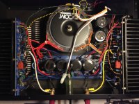
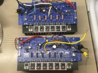
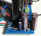
This ingenious hack squeezes in a CLC for the front end PS, while also tripling the PS capacitance of the output stage. PS ripple is so low on the front end that my Fluke meter can't read it, and PS ripple on the output stage is cut to one-third.
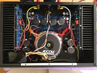
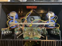
I put taller feet to help cooling and dialled the bias up to almost 4W in class A, where it idles on the warmer side.
Also I put in multi-turn pots for easy bias and DC offset adjustments, <1% matched source resistors, Kerafol pads, and new electrolytics all around. Used my nibbler to cut a nice rectangular hole for the power entry. Very pleased!
Attachments
")
Andersonix,
A few hours after your mosfets were dropped at the post office, my adcom arrived.
Did you go CRC or CLC?
I’m going to run this from 80-500hz on JBL 15’s. I’ll probably let it run stock for a while until I learn about more about the amp.
I’m thinking replace electrolytic caps due to age, and maybe go for CLC or CRC PS while I’m at it. Plus add Snubbers. Otherwise I’m thinking “ain’t broke, don’t fix it”
Attachments
Last edited:
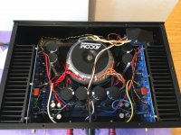
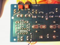
The 5400 has separate transformer windings for the front end and output stage power supplies. I squeezed in a CLC in the front end PS, using a 33mH 120mA inductor (Fastron 11PHC-333K-50) and 1200uF caps. It has a pretty high DCR 77 Ohms, so maybe a bit too high of a voltage drop here.
For the output stage I just connected the additional caps in parallel, since I didn't want to rewire the bridge rectifier.
For the output stage I just connected the additional caps in parallel, since I didn't want to rewire the bridge rectifier.
Attachments
- Status
- This old topic is closed. If you want to reopen this topic, contact a moderator using the "Report Post" button.