Hello everybody, with reference to tubes, I am a 67 years old newbie, although I am an experienced digital and microsystems design engineer.
Along with a good friend we decided to build a SE stereo audio amplifier. He is the owner of several pieces of excellent famous brands class A amplifiers, meaning that he knows how they sound. I honestly prefer solid state devices, but, as we are taking all this as a hobby, learning and having fun is the main point here.
So take this as a sincere apology to those experts that this forum is full of, begging for your mercy and patience, which I respect, in my consulting.
When I was almost a child I built some push pull tube audio amps but always following some trusted schematic. I was lucky and enjoyed the ride.
In this case, and many years after, we started by buying these 4 books from Amazon:
Book #1
Book #2
Book #3
Book #4
This was interesting reading but to be honest I found some errors in the amplifier schematic and also typos. I made my own simulation of the circuit using LTspice, and send it to the author, who was very kind to reply and also approve my proposed changes and corrections, most of them because some component values explained in the provided videos, differed with those in the printed text of the books. Grid polarization values and confusing data about number of turns in the output transformer, resistor values in the power supply, etc.
Once I had all these more or less clear, I focused on building the power supply transformer, filter chokes and finally the output transformer. I have access to a friend's professional winding machines, so we built the power transformer and chokes in just one evening. Measured chokes' inductances, they matched those of the calculations.
I found the output transformer procedure quite straightforward and I collected all the calculation in an Excel spreadsheet, that worked fine.
Here are some pictures of transformers and chokes:
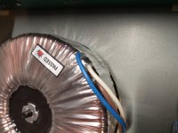
Power transformer
Choke view #1
Choke view #2
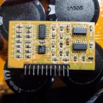
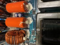
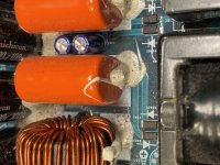
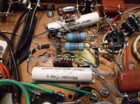
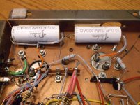
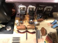
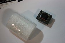
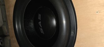
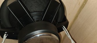
Output transformer view #1
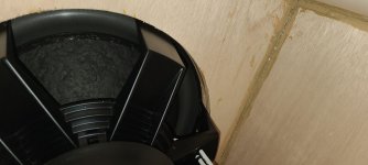
Output transformer view #2
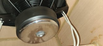
Output transformer view #3
Output transformer view #4
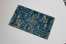
Pi bobbin
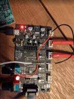
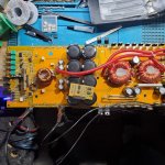
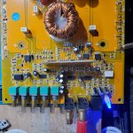
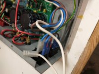
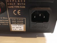
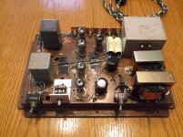
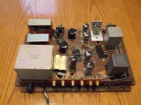
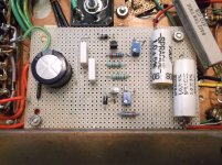
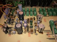
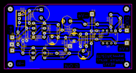
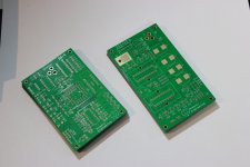
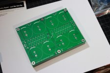
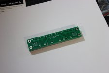
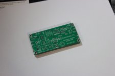
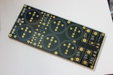
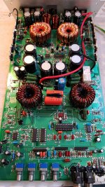
Power supply
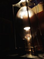
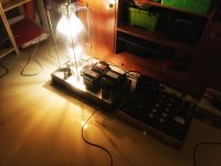
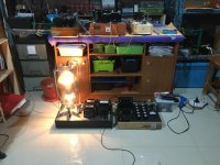
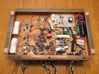
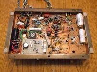
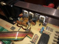
Wooden 300B amplifier
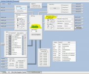
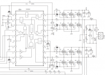
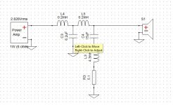
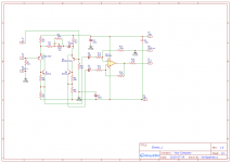
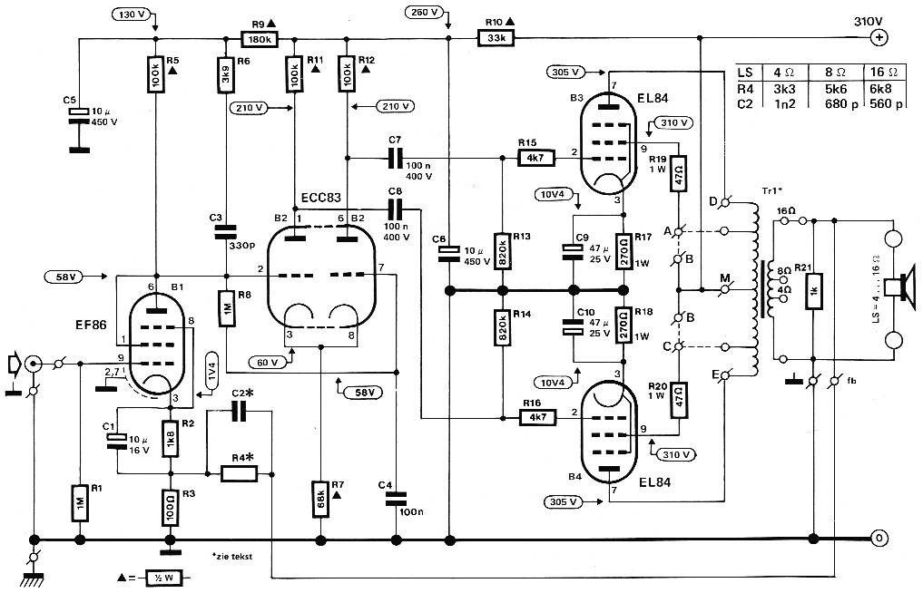
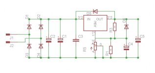
I will not reproduce any original images from the books, if somebody is interested it should honor the author by purchasing the books. But I can offer a printout of my own LTspice simulation, that involves some intellectual dedication in putting the pieces together with tube models, some hours working over the circuit errors and specially the output transformer model. The rest of the circuit is pretty conventional, there is nothing new about it. Even more, I deleted the NFB loop that was taken not from the output transformer secondary winding but from near the 300B grid. As I said before, some values shown are not the original ones and I have made corrections. The complete circuit is up and running assembled over a piece of wood and the obtained voltages and signals seem to be normal. They perfectly match the simulation.
Simulation corrected schematic
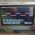
Speaker output waveform
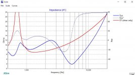
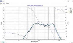
Simulated frequency and phase response
So then, what's the problem Bob?
😕
Once the output transformer is connected and loaded with an 8 Ohm resistor, the output is only 500 mV. The amplitude measured at the 300B plate falls from a nice large 200 Vpp swing to a poor 37 Vpp. Changing the output resistor value or reconfiguring the secondary taps and windings, the voltage raises. The best I could get was a 7 Vpp signal, with a relatively good frequency response.
Perhaps I made a mistake here - sorry guys for this: 
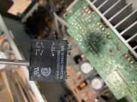
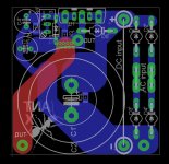
Changing the original spec from a regular multiple layer transformer to a PI winding transformer. If you take a look at the output transformer pictures, I designed and fabricated with my 3D printer, a non standard bobbin former to accomodate 7 PI parallel vertical windings; 3 of them for the primary and 4 for the secondary. This hand made custom transformer complies with the original M4 GOSS lamination size, number of turns and gap specification as shown in the transformer book.
When taken out from the circuit and measured with an LCR meter, the values seem to be normal. 12H for the primary and 116 Ohms resistance. The instrument also shows the calculated impedance that reads around 3K Ohms. Primary and secondary resistance values are also normal and as expected.
But all this measurements are not "in circuit" and there is no DC component at the primary, that should be between 60mA to 100mA.
All the signals from the input up to the 300B grid are nice and perfectly normal. So all the suspicions point to this "innovative" transformer winding probably shorting the plate voltage swing. Perhaps because there may be some special considerations when using PI winding, that in theory should be the best way to get a balanced transformer in terms of equal size windings and improved frquency response.
Secondary windings possible configurations
Before I build another brand new output transformer, I would like to hear some authorized opinion from the experts. Any ideas and help will be, as always, very much appreciated.