Hi All, First time posting, very long time reader.
I need some assistance in designing a suitable cross over for this driver.
I have a pair of them as a novelty I guess, been sitting in a cupboard for 'awhile'
https://www.beyma.com/speakers/Fichas_Tecnicas/MC115.pdf
My own DATSv3 measurements don't line up with the spec sheet I found above, both drivers measured very closely.
My results are:-
RE=6.131
Fs=727.4hz
Qts=1.49
Qes=1.883
Qms=7.146
Le=0.2372
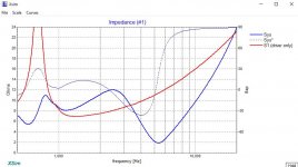
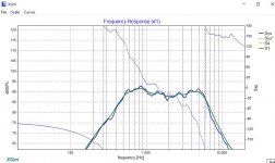
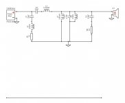
I've attached screen caps of xsim and the .frd and .zma files
How can I flatten this out?
Thanks in advance.
I need some assistance in designing a suitable cross over for this driver.
I have a pair of them as a novelty I guess, been sitting in a cupboard for 'awhile'
https://www.beyma.com/speakers/Fichas_Tecnicas/MC115.pdf
My own DATSv3 measurements don't line up with the spec sheet I found above, both drivers measured very closely.
My results are:-
RE=6.131
Fs=727.4hz
Qts=1.49
Qes=1.883
Qms=7.146
Le=0.2372
I've attached screen caps of xsim and the .frd and .zma files
How can I flatten this out?
Thanks in advance.
Attachments
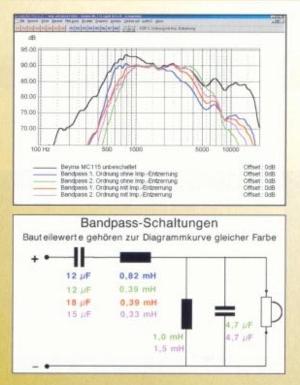
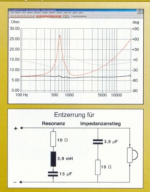
Have you seen this crossover?: https://www.diyparadiso.com/datasheets/speaker/tweeters/beyma mc115 kt2.jpg
I use a pair of MC115s in my main system, with a modified version of the above to suit my crossover frequencies (800 & 3Khz IIRC)
1st Cap 12u, 1st L, .39mH, 2nd L 1mH, 2nd cap, 4u7. I think I used a resonance filter of 8.2 ohms, 3.3mH & 18uF
I use a pair of MC115s in my main system, with a modified version of the above to suit my crossover frequencies (800 & 3Khz IIRC)
1st Cap 12u, 1st L, .39mH, 2nd L 1mH, 2nd cap, 4u7. I think I used a resonance filter of 8.2 ohms, 3.3mH & 18uF
Thanks for that. I was wondering about the 5db hump at the start of the bandpass, or should I not worry about this?
Look at closely at the top right hand graph above the crossover in the link, it shows how the variations in the crossover affect the hump
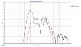
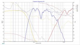
Here's a closer ( more permanent ) look at portions of that file.

The black line is unfiltered (raw) response.
🙂
BTW; ( lawofohms ) I don't think your ( zipped ) .zma file is very accurate.
- It doesn't match the one you've show within your first post ( the red line showing a minimum of @ 7 ohms in the bandpass).
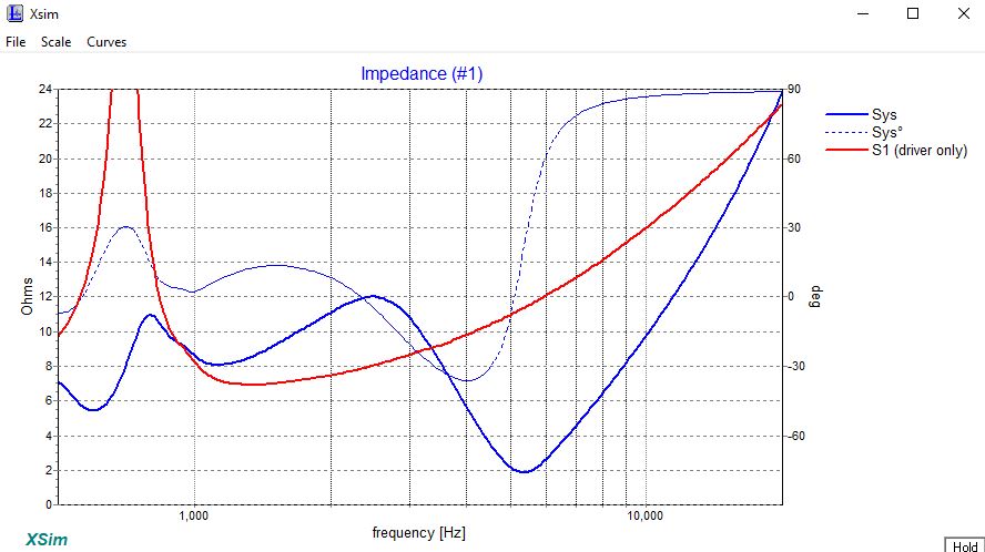
vs ( what you posted in your zipped file shows a minimum of @ 5 ohms )

The black line is unfiltered (raw) response.
🙂
BTW; ( lawofohms ) I don't think your ( zipped ) .zma file is very accurate.
- It doesn't match the one you've show within your first post ( the red line showing a minimum of @ 7 ohms in the bandpass).
vs ( what you posted in your zipped file shows a minimum of @ 5 ohms )
Attachments
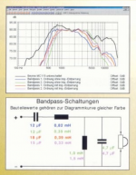
Your first crossover is not limiting the lower frequencies. A comparison of the lower end with/without a crossover is shown in the above image.
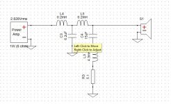
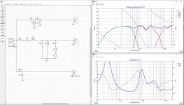
Thank you, everyone. I make adjustments to the simulation circuit. I adjusted values to match my measurements.
I smoothed out the response to ~2db ripple. but the bandwidth is narrow, well I think it is narrow or is this normal for a dome midrange.
These seem hard to control and require a lot of components.
Why are dome midrange like these used? they don't seem to be too common.
I smoothed out the response to ~2db ripple. but the bandwidth is narrow, well I think it is narrow or is this normal for a dome midrange.
These seem hard to control and require a lot of components.
Why are dome midrange like these used? they don't seem to be too common.
Attachments
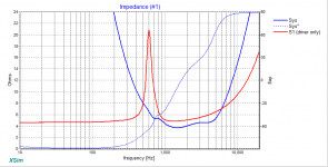
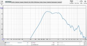
Your measurement (the driver before crossing) seems to have reflections in it. This is probably not a reasonable starting point.
try putting the impedance compensation network on the other side of the crossover.
They aren't used much because there aren't many out there, which makes them expensive, which makes them not used much, which keeps them expensive etc, etc....
They aren't used much because there aren't many out there, which makes them expensive, which makes them not used much, which keeps them expensive etc, etc....
Your measurement (the driver before crossing) seems to have reflections in it. This is probably not a reasonable starting point.
I'll remeasure with mic closer, see if that helps.
It's tricky because then you lose the baffle. Better to trim (gate) the measurement after the direct arrival.
Your measurement (the driver before crossing) seems to have reflections in it. This is probably not a reasonable starting point.
Much better - only 2db hump now (graph has no filtering)
Attachments
- Home
- Loudspeakers
- Multi-Way
- Need help with crossover for beyma mc115 2in dome midrange