Wright Mono 8 Schematic & Operating Points

Does anyone have operating points or, even better, a schematic for the George Wright Mono 8 300B SET?

I'm currently developing a 300B SET inspired by his WPA 3.5 circuit (which I found here in a post by ClefChef), which is the same as the Mono 8 but for a 2A3. Mine would use the Magnequest TFA-204 (3K, 60mA), so I'll probably run the 300B at the 350Vak/60mA op point. But I'm curious as to how George set up the 300B for the larger FS-030 and more specifically the 6SN7 input stage.

I imagine the input stage is not much different from the WPA 3.5 but it would be good to know.

Thanks,

Jeff

Mosfet Matching for F5T V3 - Correct Voltage/Heatsinking/Resistor

I've had trouble finding mosfets that are properly matched for use in my F5 Turbo V3 monoblocks. I bought several sets from reputable sellers, but I don't believe that they were matched under the conditions in which I am using them. This has caused me to blow a few sets of outputs when biasing the amp to a level where the heat sinks to approach 50C. I believe that the high bias on an unmatched, current-hogging mosfet has caused one or more of the diodes to conduct and led to smoke.

I am considering removing the diodes altogether, as some have suggested, but thought I would first try matching my own set of mosfets first under real world conditions.

I've read many of the various mosfet matching threads, but I haven't found an answer to the basic question of how to simulate the real world conditions of the mosfets in my F5 Turbo.

I intend to use the basic technique set forth by Nelson Pass in the following article, which many others have used:
https://www.firstwatt.com/pdf/art_matching.pdf

But my F5 Turbos have 41V rails, so I have the following questions:

1) Should I use a 40V power supply when testing the mosfets? Or is 15V enough?
2) How much current should I aim for with the I=(V-4)/R1 formula set forth in the article?
3) How many watts does R1 need to be rated for if the voltage is increased to 40V?
4) I plan to test the mosfets while they are screwed to the heatsink. How long should I let them heat up before taking the reading? Should I let them completely stabilize, which could take a while?
5) How closely should they be matched? I've seen 30mv, 10mv, etc.

I would really appreciate some help on this.

Thanks

FS: Electronic Crossover

FS: Electronic Crossover-Sold

SOLD I am no longer using my 2 way crossover so it's up for sale. I used 2 Marchand xm9 boards with a ps-10 power supply. This is a 24 dB/octave crossover. Here is a link for more information.
XM9 Electronic Crossover
I am including 3 sets of frequency modules, 90,120 and 200hz.
Enclosed in nice case.
Manual included.
$150 plus shipping. Venmo preferred but can take paypal.

935385d1616608508-fs-electronic-crossover-x0ver-inside-jpg
935386d1616608699-fs-electronic-crossover-xover-jpg
935387d1616608508-fs-electronic-crossover-xover-front-jpg
935388d1616608508-fs-electronic-crossover-xover-manual-jpg


Hope the pictures work, if not I can email them to interested parties.

Thanks for looking

Attachments

  • x0ver inside.jpg
    x0ver inside.jpg
    32.5 KB · Views: 263
  • xover back.jpg
    xover back.jpg
    25.7 KB · Views: 288
  • xover front.jpg
    xover front.jpg
    32.8 KB · Views: 243
  • xover manual.jpg
    xover manual.jpg
    26.5 KB · Views: 247

Active WMTM(S)W

I've just finished off a build for a pro audio setup using 12" B&C coaxials for mains, 8" coaxials for monitors and an 18" sub. The system sounds great but definitely isn't suited to running at low volumes inside my lounge room😀. I did hook it up as a 4.1 surround system, nice cinema level sound, but im sure the neighbours didn't appreciate it and the amp noise (powersoft m28q and K3) was also far to load for normal listening levels.

Anyway, it's time to start a new project to keep myself busy.

I had been following this build and really love the concept:
Scanspeak 4 Way Active DSP Build with Illuminator/Revelator Drivers

Im looking for some advice on building a slightly scaled down version using 8/4/T/4/10" drivers in a single piece enclosure. Looking at the following drivers:

Tweeter: SB acoustics SATORI TW29RN-B-8
Midranges: 2x SB acoustics sb12mnrx2-25-4
Woofer: SB acoustics SB23NRXS45-8
Subwoofer: SB acoustics SB29NRX75-6

I have a minidsp 2x8 to run the crossovers and for the moment a Lab Gruppen C20:8x (8x 250w) to drive everything during testing. I would need to swap this out for a hifi amp, probably a Nord or KJF ncore 8 channel.

I have access to a CNC machine so would be using a translam construction. I originally made up a design with a front face that is cut separately:
Fusion

I will probably ditch the seperatefront face for simplicity.

Would love some feedback on the driver selection.

External controller for Buffalo-IIIsePro38 - i2c problems

Hi everyone

Im setting up an Arduino Due as external controller for my Buffalo-IIIsePro38 and I cannot get the i2c working.

Using the Wire library example scanner, I find a single device at address 0x20. I expected to find 0x48 or 0x90.
Turning off the BIII board results in no devices found so I know it is finding something on the BIII.

Writing directly to address 0x48 just gives result code 2 - NACK.

Code:
Wire.beginTransmission(DAC_ADDR);
Wire.write(7);
Wire.write(0);
byte res = Wire.endTransmission();
Serial.println(res);
What am I doing wrong here?

SoundMagus X3500, Excursion HXA5K output PWM not working

This amp has 2 Optocoupler driver cards on the output.
(photo attached, pin configuration from left to right)
Pin 1: GND
Pin 2: Input PWM drive (coming from a 74HC00 IC)
Pin 3: Power supply transformer PWM
Pin 4: VCC
Pin 5: Output PWM drive for bank 1
Pin 6: Output PWM drive for bank 2

One side of the amp does not want to create an OUTPUT drive PWM going to the gates of the IRF640N's. Even putting in a 100% good driver card results in no usable PWM gate drive.

The driver card receives a PWM drive input on Pin 2.
Also the power supply PWM on Pin 3 is present.
The GND and VCC is also present on Pin 1 and 4.
There is just no output on Pin5 and Pin6

Almost every part on the output PWM circuit has been replaced (all the 2x and 2t transistors, 74HC00, 6n137 optocoupler). All resistors on the driver card has been checked and are OK.

Attachments

  • PHOTO_20210223_115141.jpg
    PHOTO_20210223_115141.jpg
    468.3 KB · Views: 126

Webcor 2611 morph into practice amp

My son and I are going to build his first ever tube powered guitar amp. He has a ss line6 spider 4 75 that he uses to play with the band with now that keeps up with the drummer. It models gobs and tons of different sounds kinda ok. However, like most midi/ss amps, it just can't deliver that tube amp sound. It is too loud for his bedroom, where he studies and plays his computer and guitar most of the time. We whipped up a little op-amp/ss chip amp at first, but it is too dry, and doesn't have that "tube sound" when it distorts. And guess what? He likes bluesy "crybaby" sounds and "metallica" heavy metal distortion.

We went to guitar center so he could figure out what he likes in tube amps, and the results surprised me. Contrary to my assumption that he would be drawn to the mesa/marshall amps, he has gravitated towards the vox and orange amps. Between the ac30 and the tiny terror, he probably spent an hour going back and forth. He could not pick a favorite, the vox sounded better clean and the orange sounded better distorted. When pushed into a choice, he said he would take the vox and add pedals if he had to choose. But it was too loud.

Fresh Mods

Hello all

We would like to introduce two new moderators. Sangram from India and AllenB from Australia. Good long time diyA members. Their time zones are nicely spread. Thanking them for accepting the invitation.

*We would also like to thank jazbo8 & TonyTecson for their positive long tour of duty as they retired during the recent period.

"Reason for editing"...

I've never understood this bit of internet forum etiquette. Like, where did it come from?

Why would anyone want an explanation behind you editing your own post or reply? A space is provided for such here, but also elsewhere in other popular forum hosts like "reddit".

It doesnt fit my composition style at all. Typically I write in a "multiple pass compiler" fashion. Forget saying anything coherent on the first pass. Sorry if I may post first, refine on the fly. Am I actually supposed to explain why I changed a "they're" to "their"? Someone's actually interested in that?

When I see a reason for editing actually filled out, I'm like "you've got to be kidding me"...

What speakers have you used with your Tubelab amps?

What speakers have you used with your Tubelab amp and what did you think of them?

Has anyone used lower sensitivity speakers with good results?

Here’s what I’ve used:

Klipsch KG-3 with Crites titanium tweeter - Very good sound with these.

Klipsch Forte II with Crites upgrades - These were excellent sounding speakers, especially with my Tubelab SSE. Unfortunately, I sold these when I sold my house, as I thought they would be too big for the apartment that I was moving into. I regret selling them.

Tekton M-lore (mini lore) – These have a high sensitivity rating and I really wanted to like these, as they fit my current living room perfectly. They had deep and clean bass with the SSE but they had a dark sound signature that I didn’t care for, so I moved them along.

Klipsch Heresy I – this is what I’m currently using. These sound very good. They are an engaging speaker and throw a very large image. They don’t go very deep but the bass that is there is clean and articulate.

Mains wiring two toroids each with dual primaries

Hello All,

I am making progress on my first 2-channel amplifier and deep in the middle of the "best layout" design process. I have looked all over trying to find the best solution for my mains wiring inside the case but have yet to find a proper solution.

I have two separate toroid transformers. One is the large one for the PSU and the other is a small 9v, both have dual primaries that will be wired to run on 115v AC from the mains outlet. There will be a single switch on the front panel and of course that is where the combined "single wire" for each of the "hot" and "neutral" will lead.

There are many ways to connect all 4 "hot" and all 4 "neutral" from the two different transformers and I am looking for the safest and cleanest approach.

1) I could simply strip all 4 of the red wires leading to the primaries, twist them together and solder covering the joint with shrink tube. I could do all 4 of the black in the same fashion.

2) I could also make a small copper buss plate that would accept 4 ring terminals on one end and have a single ring leading out, but then I have an exposure issue with mains. Unless I were to also build it in a box. UGH!

3) I could use a tektronix ceramic terminal strip to accomplish the same thing with identical exposure issues.

4) And last but not least I could use a proper terminal block like this one .......

2-4 Terminal.jpg

I do like the concept of this last one. It makes everything clean, safe and tidy. I can easily remove the trannies if necessary and nice solid connections. This last option while perfect is quite large as it is made for industrial power applications. No way I want it in my case, simply over-kill and not enough room.

Has anyone used or seen something similar for their diy efforts? Something that is made more for the wiring for electronics instead of huge power terminals? With some digging I found what some in the "car audio" groups refer to as a "power distribution block", but these are for 2, 4, and 8 gauge wire.

If you have a better way of making all this work properly and in a tidy fashion, I am very open to suggestions. NOTHING is outside the realm of possibilities. I want to hear your thoughts.

Cheers,

David

NAD Receiver Turns On Then Off

NAD Receiver Turns On then Off

I have a NAD receiver that will not stay on. It turns on for a couple of seconds and then clicks off. There is a small circuit board with a relay and a .0047 uf disc capacitor, I removed the cap and measured it with a capacitance meter and it tests .0043 uf.

The schematic indicates some voltages coming off of the power supply so I measured them with my DMM with the common lead attached to the chassis ground and the voltages read as indicated.

This is new territory for me (noob alert) so I'm looking for some guidance. 🙂

Here is a link to the hifiengine library with the service manual...

NAD 701 AM/FM Stereo Receiver Manual | HiFi Engine


.

CED/UNSET/CORONA-like ECC88 hybrid cascoded driver

Hi,

I want to share the results I've obtained simulating an hybrid cascoded driver with local feedback à la CED/UNSET. ...it's like retriodize a cascoded triode.

The idea has been inspired by Tubelab's CED and UNSET and from SpreadSpectrum's CORONA amp (https://www.diyaudio.com/forums/tub...a-low-distortion-a2-dht-se-amp-prototype.html)

1.4Vpp input give 140 Vpp output, and a THD of 0.047%:
Code:
Harmonic	Frequency	 Fourier 	Normalized	 Phase  	Normalized
 Number 	  [Hz]   	Component	 Component	[degree]	Phase [deg]
    1   	1.000e+03	6.706e+01	1.000e+00	   -0.76°	    0.00°
    2   	2.000e+03	3.151e-02	4.699e-04	   97.42°	   98.18°
    3   	3.000e+03	8.770e-04	1.308e-05	   98.39°	   99.15°
    4   	4.000e+03	3.044e-04	4.539e-06	  177.17°	  177.94°
    5   	5.000e+03	1.170e-04	1.745e-06	 -142.30°	 -141.53°
    6   	6.000e+03	3.823e-05	5.700e-07	 -172.56°	 -171.80°
    7   	7.000e+03	5.862e-05	8.741e-07	  165.29°	  166.05°
    8   	8.000e+03	5.931e-05	8.844e-07	  178.26°	  179.02°
    9   	9.000e+03	4.730e-05	7.053e-07	 -175.67°	 -174.91°
Total Harmonic Distortion: 0.047008%(0.047001%)

I've obtained ppm-like distortions with higher local-feedback ratios, but everything still need to be optimized.

Attachments

Electro-Voice HP9040

Hi, all

Using a pair of Electro-Voice TS940D LX pro cinema speakers in my home set-up. They're the small horn variant with the HP940 horns, but I'm in the process of replacing them, within some two weeks, with the bigger HP9040 horn that also fits on the TL606DW bass cabs (and thus they're called TS9040D LX).

Do anyone here use the HP9040 horns or are otherwise familiar with their sound? How do they compare to other, similarly sized horns (or smaller, for that matter) like the JBL 2360 or earlier EV variants?

The compression driver used in my EV set-up, and that will be mounted to the HP9040's, is the DH1A.

Please chime in.

Noob question: Xsim wattage distribution, take it as read?

Hi,


I'm new to all this stuff so please forgive my constant underqualifed questions 😉


I've finished siming my XO and I want to purchase the parts. So I opened xsims wattage distribution graph, as recommend, in order to find out which resitors I needed to not A: melt or B: burn my house down.


Xsim is telling me that I need up to ~60watt resitors in a 100watt system (see photo). I'm new to all this so I don't know if thats normal or it sounds abit excessive? Just wanted to cross check with you lovely peolpe before I go off and buy the components.


If I do need a 60W reistor, is it possible and beneficial you use 3x 180ohm 20W resitors in paralell?


Thank you! Luke

Attachments

  • watt what.JPG
    watt what.JPG
    309.2 KB · Views: 101

Evaluating 15v bipolar power supply's performance

This is a question from a newbie who will be borrowing a scope for this experiment.

I have 5 different PS to test, all set to about the same output voltage. What am I looking for to select best PS for a pre-amp or phono stage or a headphone amp that run on 15-18v bipolar supply?

What's the criteria, can I use a scope to see it and generally is this the right approach of selecting a power supply prior to doing the listening tests?

Thanks!

Apple's HomePod, what is this bottom firing horn that provides directivity control?

Apple just announced their smart speaker called the HomePod. It looks to incorporate some advanced speaker design principles. But there's something that's scratching my head. What the heck is Apple doing with the tweeters???

L6L7Rj5.png


Originally I thought this is just 7 tweeters in a circular array that does the same thing as the Beolab 90 to provide directivity control. But a closer look, and Phil tells us that the 7 tweeters are actually firing into a common down firing horn.

So what is Apple doing here? How do you even get treble out of a down firing horn that is practically touching the surface the speaker sits on?

Now even if the treble gets out, how can there be any horizontal directivity control when it is from a vertically mounted horn? The only way I can see it work is if the phasing happens within the horn, and it is already reduced into a narrow beam, which is then reflected by the horn to hit the surface at a designated angle, which is then reflected by the surface to our ears.

Any thoughts?

Advice on speaker and XO impedance, please explain to me like I'm 5 years old...

Hi,


Im building a boombox type set up so I dont need stero audio, my plan to econonimise on time and money is only make one crossover curcuit, split it half and run tweeters on L and woofer on R with the amp potentimeter shorted to mono. I've simmed up this design on Xsim, all is well but the impedence values change drasticly whe I "cut the system in half" as explained.


This has lead me to one question... whats the deal with impedence man?
More specificaly how do I tell if my impedance levels are "safe" for the amp and system? Also how do I understand this is terms of xsim and more genrally?


Heres some screen shots for refference:
If these impedance values are problomatic any surgestions on how I might fix them would be greaty apriciated :worship:


Thanks, Luke.

Attachments

  • Capture.JPG
    Capture.JPG
    306.6 KB · Views: 142
  • tweeter channle.JPG
    tweeter channle.JPG
    300.2 KB · Views: 144

Quad 606 MK2 drawing 55 Watts in standby mode

Hi, I own a Quad 606 MK2 and I measured it's power consumption. It seems that when in standby mode, it already uses 55 Watts, and while playing music it uses between 55 and 60 Watts. I didn't expect it to use such a lot of power being idle. Is this normal? I searched the internet but didn't to manage to find information about idle power consumption...

Calibrating bias and DC offset

Hi All,


I'm trying to calibrate the bias and DC offset of my Musical fidelity B1 amplifier.
The B1 has 2 adjustment pots on each channel.

Beside the fact that the readings are "all over the place" and not stable the DC offset that I measure on one channel of the speakers outputs appear in minus and the other channel measured in "+", like one channel is in reverse polarity.
Why does it happens?

Please help! Looking the schematics for: K-AMP Integrated Power Amplifier DIY Kit

Please help! Looking for schematics for: K-AMP Integrated Power Amplifier DIY Kit

I have a pair kits for the:

K-AMP Integrated Power Amplifier DIY Kit
ref Krell KSA 100 (Single Channel)


1196550770116325018.jpg


Unfortunately I bought these stuffs many years ago and I lost the schematics and parts list what I need to build them up...

Please help me if you have it...
Many thanks in advance!

KIT 18sound

Hello everybody.
many people tell me that the 18sound KIT I own is not suitable for home listening but they do not explain why with technical details.
I'm not an expert, can you explain it to me please? .
I attach technical data images.
bye thank you .

Attachments

  • 18sound_15 2ways1024_1.jpg
    18sound_15 2ways1024_1.jpg
    43.8 KB · Views: 574
  • 18sound_15 2ways1024_2.jpg
    18sound_15 2ways1024_2.jpg
    131.2 KB · Views: 569
  • 18sound_15 2ways1024_3.jpg
    18sound_15 2ways1024_3.jpg
    62.9 KB · Views: 572
  • 18sound_15 2ways1024_4.jpg
    18sound_15 2ways1024_4.jpg
    63 KB · Views: 561
  • 18sound_15 2ways1024_5.jpg
    18sound_15 2ways1024_5.jpg
    94.1 KB · Views: 553
  • 18sound_15 2ways1024_6.jpg
    18sound_15 2ways1024_6.jpg
    131.2 KB · Views: 239
  • 18sound_15 2ways1024_7.jpg
    18sound_15 2ways1024_7.jpg
    134.5 KB · Views: 141
  • 18sound_15 2ways1024_8.jpg
    18sound_15 2ways1024_8.jpg
    56.4 KB · Views: 162
  • 18sound_15 2ways1024_9.jpg
    18sound_15 2ways1024_9.jpg
    60.3 KB · Views: 199
  • 18sound_15 2ways1024_10.jpg
    18sound_15 2ways1024_10.jpg
    51.4 KB · Views: 182

Need some education - Negative feedback - Too much ?

Hi all, first thanks for helping me out with the phase splitter here in this thread

I was super enthusiast that I got the phase-splitter output swing going to ~35Vpp to drive the output tubes. Now I re-connected the negative feedback and the amplification factor from the first stage pentode dropped from x40 without NFB to x13 with.

And now I do not reach what I wanted on the output tubes / phase splitter
At 2Vpp in Pin 9 gets 26Vpp and Pin 1 has 24 Vpp
The NFB Signal on Pin 3 and 7 is 1.6Vpp

So is this to much ? Normal ? Any suggestion on improving the balance between amplification and negative feedback correction with the 10K resistor? I could add an extra tube stage but that I do not see in other similar simple diagrams and would like to avoid that.

Attachments

  • Amplifier.png
    Amplifier.png
    711.4 KB · Views: 558

Best output devices for NCC200/NCC220

Will be building a couple of Avondale NCC boards in the summer, the original output device is BUV20, now discontinued. Current builders are using MJ15003G. Which one would you choose if you had the option? These boards will be used for an unregulated power amplifier in dual mono.

The BUV20 can still be found at a hefty price, from Motorola. Not sure if they are originals, but seller has a 100% feedback rating. MJ15003 can still be found at vendors like Newark and Mouser.

Any advise? Thanks to all.

Phase, can I run 18db woof with 6db woof circuit ?

In a 2-way, imagine a loudspeaker crossing 18db @ 1.2khz to the tweeter.

I’d like to add a bass box to run alongside of the 2-way loudspeaker.
Another woofer with a single inductor (to add bass or baffle step).

That inductored woofer run in parallel with the entire 18db crossed 2-way loudspeaker.


I’m thinking no because every 90 degrees is more delay.
So the 18db crossed woof would be delayed by ¾ wavelength while the 6db baffle step woofer would only be ¼ wavelength delayed…….
They would be 180 degrees out.

Sounds about right ?

Linear ATX power supply

Well, not quite ATX as it doesn't fully conform to the standard but certainly does the job.

Some time ago i bought a Streacom fanless case and built a small headless music PC around an Intel DH77-EB board with i3 3220T low power processor. It was meant to replace and possibly improve upon a Dell i5 XPS laptop.

The PC is wired to a router and plays music files off the network through a USB port. The usb/dac side has galvanic isolation of the I2S signal and two levels of reclocking, so should be very immune to the source.

Built with a "nano" power supply, initial results were not encouraging. Despite being fanless and spinning-disk-less it sounded worse than the Dell laptop. The nano is similar to the better known pico - a tiny 80W switcher which takes 12v and produces the required ATX voltages and logic. The first step was to improve upon the 12v raw dc.

Replacing the raw dc with a linear PS regulated to 12.6v proved the most significant step towards better sound. Now the fanless box was indeed a better source than the Dell. It stayed like this for months and generally performed up to expectations.

Of course, got itchy fingers again, so the "nano" had to go. The motherboard i use may be much easier to power up than more sophisticated boards. It only requires backup power to be applied before any of the other voltages. So, +5v backup is delivered by a 7805 - shown on the circuit as an LT1117-5. All other regulators are off before the power button is pressed. Well, not quite off - down to 1.25v as it was much easier to control the regulators like that, but it doesn't seem to make any difference.

The right hand side sink of the case takes care of the processor cooling and barely gets warm. My regulator proto-board is mounted on the other sink and probably gets up to around 40C at 25C ambient.

Compared to the nano powered from a linear supply this is a bit better, mostly in low bass, ambience and soundstaging. It is certainly not a night and day difference. Would i build it again? Yes, in a flash 🙂

It may be interesting to increase the number of regulators, so, per example the SSD would get its own power. It may also be possible to circumvent some of the MB switchers, possibly apply 1.5v directly to the memory. Got too many other projects to pursue at present, but maybe one day...

Attachments

  • streacom case open sm.jpg
    streacom case open sm.jpg
    469.6 KB · Views: 1,861
  • linear ATX.pdf
    linear ATX.pdf
    18.5 KB · Views: 1,123

BK16 kit with Fostex FE168NS 6.5" Drivers-- Adventures in Tung Oil Application

Edit: not sure why the pictures are squished. Computers!


Been eyeballing these kits for awhile and bit the bullet a short time ago. I was super impressed with my Kanspea PC setup and I wanted a project that would allow me to try my hand at varnishing. Or treating wood. Or whatever you call it-- I frankly have no idea what I'm doing as I've learned upon doing further research AFTER I began working with Tung Oil. Learn from my mistakes and, maybe, don't be too afraid to use it because I'm pretty pleased so far. It's a very unique finish that really "respects" the wood. I've learned terms like Cathedral and Phloem. I'm getting a lesson in delayed gratification and a couple splinters in my index finger. I'm loving seeing the bones of the cabinet made prominent as opposed to an occluding veneer.

To begin (and I'll edit if there's any rule against posting this) I got the kits from Madisound. I've bought a few things here and there from these guys and they have always been excellent. Highly recommend. I imagine most here are familiar with them but you never know.


I'm a fella that knows my limitations. Assembling these cabinets was way above my pay grade so I paid a local carpenter and all around great guy to assemble them for me. If you're in Cape Cod and want a speaker assembled or a 17th Century side table repaired shoot me a message and I'll connect you with him. He said the quality of the Baltic Birch was superb, he was quite impressed. He also said assembly was pretty challenging even for someone that knows what they're doing, pointing out a Witness Mark in an example photo in the instruction sheet where the carpenter didn't quite get a perfect match. So I'm relieved I didn't try it myself. Here's a pic he sent me of the clamping situation. The instructions don't lie, you need clamps for days. Lots of clamps and a couple extra. If you want to do the assembly yourself... get clamps.

An externally hosted image should be here but it was not working when we last tested it.


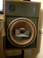
And here's the assembled, raw cabinets:


An externally hosted image should be here but it was not working when we last tested it.


First step for me, sanding. I started with 220 grit and then 330 while dusting with a 3" Purdy brush. Recommend doing this plein air unless you want to coat your work area in ultra-fine, chalky particulate. I was fortunate to catch a sunny, balmy 37 degree day and took advantage. Once the cabinets were silky smooth and little residue showed up on the white glove test I moved on to the first coat of Tung.


Fortunately I did do some research on Tung products. Turns out many aren't actually Tung Oil. Trust no-one! I guess because it takes such an abhorrently long time to cure and is peckish about air flow, humidity, ambient temperature, and the Kelvin rating of your work lights most suppliers add a drying agent to their Tung Oil. Some brands of Tung Oil purportedly contain no actual Tung Oil. Long and short I ended up picking Hope's 100% Tung Oil:


An externally hosted image should be here but it was not working when we last tested it.


For the first coat I mixed the Tung Oil 50/50 with plain old Turpentine. I had read this assisted penetration. Seemed to.


For application my intention was to sort of flood with a rag and massage it in. I chose the softest rag I had around and tried a test area. Fibers everywhere. Rags a no-go. I moved to a chip brush. This worked significantly better but eventually detached brush hairs became a nuisance. A mild one, as about fifteen minutes after the first coat was applied simply hand rubbing the cabinets removed all of them. I often felt I was molesting my cabinets. There's a definite sensuality to massaging oiled up wood with your bare hands. I've accepted this part of myself and I think I'm starting to get "wood guys".

An externally hosted image should be here but it was not working when we last tested it.


That's enough for now I'll continue this post later.

Mark Levinson 31.5 Transport - how to open power supplies on one

Mark Levinson 31.5 Transport - how to open power supplies on one?

Hello everyone,
I have been sent this M.L.31.5 Transport and once it boots, it shows servo error 14B1 and flashes 3 LEDs on the front panel.
I would welcome a Service Manual if anyone had one or even if I could get an advise on how to brake into the power supplies on each side of it.
Although I promised the poor guy who bought it that I will only have a quick look at it and have already spent 3 hours, the player is so interesting, that maybe it warrants a good inspection of all boards before I return it to him defeated.
I am embarrassed for I have never failed to take a component apart but it appears to be more quirky that most...
Cheers and thanks
Roman

DSP Crossover project

Thought I'd share my DSP project just in case it is of use to anyone. This will initially be used to merge my active monitors and twin subs and sort out room EQ, but when I get some time I plan on using it for some three way speakers.

Pictures below.

Chassis - I have Rotel RMB1066 6 channel power amps (x2) so wanted something to match (ish) so bought a "for spares" Rotel RDV1060. This is really nice as you can remove the front fascia, tap some exiting holes, add a plate of aluminium and make it look nice. Rear is similar, just chop out the back and add a plate.

DSP - I only have digital sources so got a Minidsp Nanodigi

miniDSP Kits : nanoDIGI 2x8 K

Dacs (x4) - Khadas Tone Boards

Tone Board: Hi-Res Audio Board Designed for Music Fanatic.

USB input - the minidsp does not take usb streaming so bought an ebay XMOS208 input board that had a spdif output all ready to solder

U208 XMOS USB Digital Interface DAC Decoder Module Support for PCM DSD New | eBay

Powersupply - Anker 6 port USB 60W charger - measurements here - Test of Anker 60W 6-port A2123

Anker PowerPort 60 W 6-Port Family-Sized Desktop USB: Amazon.co.uk: Electronics

Complications - I wanted to add the following function which have complicated it a bit -

  • Rear IEC three pin fused power socket and Front master switch to Anker PS.
  • Individually turn the DSP and DACs on/off.
  • Switch between a rear COAX SPDIF and the USB SPDIF.
  • Rear Toslink
  • Space the rear analogue output sockets the same as the RMB1066
  • Use the final Anker port for a rear USB power socket (for powering my Chrome Cast Audio).
  • Power lights for each item (combination of LED bulbs and fibre optic light pipes).
  • Re-route the Minidsp IR sensor to the front panel.
  • Front usb port for DSP programming and front port for USB streaming
Progress so far -

Case done, front and rear panels done and painted in satin black, all switched etc. and main boards mounted. Power connected, coax from DSP to DACs done. Tested Power, DAC and USB - all work fine.

Still to do -

Wire DACs to rear panel
Find a power fuse to fit (seems to be smaller, maybe european?)
Add power indicators
Download and istall Minidsp software and check DSP out.

Ideally I will remake the front and panels using laser cutting but hand made is fine for now.

Anyway, there's my little project, all comments welcome (and no, tidy wiring is not my strong point).

Attachments

  • IMG_8404a1.jpg
    IMG_8404a1.jpg
    153.6 KB · Views: 1,738
  • IMG_8405a2.jpg
    IMG_8405a2.jpg
    150.1 KB · Views: 1,799
  • IMG_8409a3.jpg
    IMG_8409a3.jpg
    220.4 KB · Views: 2,133
  • IMG_8370a4.jpg
    IMG_8370a4.jpg
    162.8 KB · Views: 1,804
  • IMG_8397a5.jpg
    IMG_8397a5.jpg
    193.2 KB · Views: 1,689
  • IMG_8401a6.jpg
    IMG_8401a6.jpg
    201.1 KB · Views: 696

Latest project - a bass amp with sweep tiubes

The latest in the series of tube amp projects in progress - a bass amp. My original idea was a big bruiser using 6550’s, but that ended up as a hi-fi monoblock and eventually a pair. Didn’t want to commit that much resources to something I’m likely only to dabble in - I’m no “real” musician but I do build hi-fi PA gear. I wanted something more a match for the intended speaker, and didn’t cost $1000 to build for the “tube bass guitar amp.” Home brew power transformer, $5 output tubes, but decent quality output iron - the only place I spent any real money. Got most of it built now, in the process of getting it up and running. Pretty standard pre amp, but added a sweepable mid. Power section pretty simple and straightforward - but with a couple twists. All octals to make wiring easy. 26DQ5 output tubes with G2 fed from a low voltage tap on the main power supply, and a true LTP phase splitter using the negative rail. When you make your own power transformer from scratch you can just put on all the windings you need to make something work. The original “donor” core was a 500VA EI I picked up for $15 some 20 odd years ago. I still had three left out of a batch. The schematic I ended up with to follow when I get on the other computer with my design software on it.

Attachments

  • 2D868A15-0117-4AAA-835A-4515E9BF2BF7.jpeg
    2D868A15-0117-4AAA-835A-4515E9BF2BF7.jpeg
    129.1 KB · Views: 155
  • 37D8BB2A-8DC2-4E91-90C1-72A3B549C8F8.jpeg
    37D8BB2A-8DC2-4E91-90C1-72A3B549C8F8.jpeg
    456.5 KB · Views: 154
  • 80C2F6FF-D4D1-4553-979A-96D2795F6C0E.jpeg
    80C2F6FF-D4D1-4553-979A-96D2795F6C0E.jpeg
    113.6 KB · Views: 166
  • 45D13637-E407-4FE0-ACC5-C2827AAD1FCF.jpeg
    45D13637-E407-4FE0-ACC5-C2827AAD1FCF.jpeg
    418.4 KB · Views: 147

Woo Audio WA 2 making noise(metallic noise) when sitting on top my SONY PVM CRT

Woo Audio WA 2 making noise(metallic noise) from headphones when sitting on top my sony pvm crt monitor, I don't wanna put my amp anywhere else because I wanna see the amp while I'm enjoying retro gaming/music.

can anyone explain to me whats causing this noise??

Attachments

  • 20210316_224903.jpg
    20210316_224903.jpg
    574 KB · Views: 130

Modding a 4 or 5 pin fader to work on a 3pin input

Hi, iv been having trouble finding a cross fader for my BEHRINGER DDM4000

I at 1st tried the Infinium X1 but it did not work. it just got hot.

im buying a replacement however to make sure it was not down to a faulty fader. if this fader does not work however then my mixer is basically dead in the water unless i can get a fader back on.

My options are as follows.

Connect a 4 pin Behringer CFM-1 OR 5 pin Behringer CFM-2 fader
to the board of the DDM4000

Now being a new born novice i have no idea how to go about this, moreover i dont even know if it would work.

Has anybody sucsefully attempted to do this on either a DDM4000 or any other mixer.

If so i would be greatfull for any advice you may have to offer.

thank you.

pics of CFM-1 CFM-2

4pin — ImgBB


5pin — ImgBB

Pic of the original DDM4K fader

49-BC5-DC3-8916-414-D-9792-3712-CABA69-A5 — ImgBB

Channel Imbalance, maybe pre-amp - possible causes?

Yamaha RX-V850, the front left / right channels are imbalanced.

The balance and volume pots are not the cause, they measure proper.

The Amp section is fine as well.

The pre-amp outputs have very different peak-peak voltage, I forget the values but recall the overpowered channel clips at around half volume.

not sure it matters since amp is fine, but bias is okay and nill dc.

I figure somewhere in the pre-amp section on the spoiled channel there are out of spec components causing excessive power to flow through.

But yea, do those symptoms indicate any leads as to the cause / possible causes?

Acoustic properties of mitre bends

I have come across a brief paper on compensating for the apparent change in length when folding a transmission line.

It suggests narrowing the path at the corner either by placing a baffle at the inside of the bend or by cutting the outside corner.

I wonder whether someone has tried this in their speaker designs?

Here is the link. The references are worth a read if you can follow the maths, unfortunately they are behind paywall.

Rockford Fosgate Punch 225x2 - one Fet gets hot

Hi!
My name is Andi and i am new to this great forum!


I started a new hobby trying to repair my rockford amp and i need some help 🙁

I have a broken punch 225X2 on my table and i am out of ideas what to check next.

The backplate says 225.2 and the mainboard has 225X2 printed below the transformer, the big Capacitors are from 1998.

The board prints: PC-1885-A

Now it has clean audio but i still have problems with one output FET which gets hot after a short time.

I love spending time on that thing for learning and i stopped counting hours 😀

I have no schematic , i just tried to find faulty components.

Now i am at a point where i need to be kicked to the right direction and hope to get some help from the pros 😱

Here is what i did so far:

The PSU - FETS were all ok, i replaced all output fets , some SMD Resistors , diodes , all source resistors.

Negative voltage at the opamps was way too high, so i replaced the negative regulator.

If i am right, D7 was also defective and i changed it.

Both channels produce clean audio.

Idle is around 0.8-0.9 amps. I borrowed a scope and adjusted the bias channel until the signal at the zero point became clean.

The left channel has Q126 which gets hot after 20 secs. when i pull around 5 amps out of the amp with a 50Hz sinus signal applied.


The other channel is fine, i got around 180 watts at 4 ohms after a very short power test.


In idle everything is ok.

I tested it with 3 fingers and the finger on Q126 is the first which starts to hurt 😀
Others are warm but not too hot.

On both speaker terminals i have around 25mV DC.

If i try to get more power i am sure some parts will start to burn.

Some suggestions what to check next are much appreciated!

If you need more infos , let me know. I have not much experience with amp repairs, years ago i was able to repair a punch 250m with infos of this community which turned out it was succesful, its still working!

Best regards and thanks in advance!
Andi

IPAD AIR 2 16GB Gold

Selling my IPad Air 2. It's worked perfectly since I bought it. Wi-fi only, no carrier. Really nice condition.
Gorgeous display. iOS14. Tiny little dent in far corner (see pic) that you'll never even notice. Comes with charger and Anker bluetooth keyboard/cover.
Battery power is still strong.

$170 Shipped U.S. Paypal.

Attachments

  • Ipad 3.jpg
    Ipad 3.jpg
    622.5 KB · Views: 132

Eminence Lab15 - Sound Quality

Hi there. I'm curious about the sound quality of Eminence Lab15 and the other Lab subs. Are they good music woofers? I'm not overly experienced with high end drivers in the sub frequency. I would be crossing under 100hz, likely closer to 50hz if possible to a large pro woofer.

It looks good on paper but I have had mixed results with some Eminence drivers. Probably too high of expectations combined with inexperience so looking for opinions from others who have more experience with this driver or anything to offer.

Thanks

Strings in orchestras sound out of tune

This is probably just me, but here goes...
I love some classical music, but as soon as the violins start up it's like fingernails on a blackboard to me. Am I alone in this? What could be causing it?

I have a theory that it is something to do with them being fretless and the players are going for the true note instead of the note that for example a piano would play. On a piano, E =659.26 Hz, but on a violin (or viola or any fretless stringed instrument) a perfect E at 440×1.5=660 Hz can be played. Is this difference big enough to notice?

Brian

Soundstaging and imaging with soffit mounting?

Hi guys

So I am moving into a new place, and in the new place I will have to move my main system into what will be my study. But this room is small (circa 3m x 3.5m). I will be putting (floorstanding) shelves on all the open walls (books and LPs). So either I put the speakers in front of the shelves, which will put me about 1m away from the speakers, or put them against the walls, and build shelves that will fit around them. The listening distance will not be much better, but it will be better. I am just wondering how this will affect the sound.

On the speaker front I currently have two options.
1. I have a pair of AR91 speakers
2. Alternatively, I have a pair of Wharfdale Super12 RS/DD (I have actual measured TSPs for these) that I can mount in Tannoy Berkeley cabinets (I have uncut baffles for these, so I can go vented or sealed). If need be I can also custom build a pair of cabinets for these (the recommended size for these is 5 cu.ft. and the Berkeley cabinets are only 3.5 cu.ft.).

So, what would you guys suggest? I do have a pair of P Audio 15" woofers, with P Audio PH220 alu horns and compression drivers, but I don't think this combo will work for nearfield listening, so the above two are my main options. Any suggestions will be appreciated. Note, I don't have the budget to buy something else, so these are my options.

Thanks,
Deon

NAD 2700 Alignment problem.

Hello,

I replaced the relays in my NAD 2700 THX Power amp so I thought I would do an alignment while I had the box open.

The problem I'm having is with setting the Idling voltage. I did this a few months ago and had no problem getting the 7.5mV. Now the most I was able to get was 3mV maxing out the trim-pot. The amp was making a buzz when I got that high. I'm getting the same on both channels. I went ahead and set both channels to about where the trip-pots were before I started, this gives me about 1mV. I played some music through it, it sounds pretty normal.

Any idea's where to start?

I'll probably take it to a shop (any recommendations in San Jose California?)

Thank you for reading. 🙂

Attachments

  • Screen Shot 2021-03-21 at 5.37.06 PM.png
    Screen Shot 2021-03-21 at 5.37.06 PM.png
    95.7 KB · Views: 115

D.a.s cx-12 data needed

Hello I have purchased a pair of d.a.s cx12 fullrange speakers, they were a very good offer, but I have been unable to find any specs on them, they are mounted in a stage monitor cabinet, I would like to build a new enclosure, I attach pics, the pics are not of mine, but pulled from internet, seller guarantees they are in mint condition.
So if you have specs it would be most welcome

Attachments

  • Screenshot_20210320-095920_eBay.jpg
    Screenshot_20210320-095920_eBay.jpg
    729.4 KB · Views: 131
  • images (1).jpeg
    images (1).jpeg
    6.9 KB · Views: 127
  • Screenshot_20210320-100855_eBay.jpg
    Screenshot_20210320-100855_eBay.jpg
    848.4 KB · Views: 131

Goldmund modification

Hi, i was just playing with the bias circut when the cordell output correction idea cae to mind.
In this case i was looking for a "simple modification" that makes sense.

At first comparing to resistor bias or fixed bias...

Could it bee that this current driver drive 😉 ?

This simple bias with error correction ? Any comment ?

Bias current abt 7mA.

Attachments

Bryston power supply mods (MPS1 to MPS2 or PS3)

Unlike the schematics you can find on the internet for many Bryston products over here I can't find it for their power supplies.

I was wandering if there are people who have made modifications to a MPS1 so it could meet the level of a MPS2 or PS3 power supply?

Or did some modifications like Alfetta87 describes at internal mods for the BP25

I've changed some parts inside, like the voltage regulator (standard are cheap fixed regulators), bypassed the output caps, and varniched all with C37 lacqueer.

Altec VOTT A7 using CAD and CNC

Whilst I'm developing a smaller Altec bass horn for my own system, I'm using part of that experience to do a CAD/CNC Altec VOTT A7 cabinet.

Attached are the initial drawing from my engineer CAD mate.

This will be built in Euro Birch Ply, 19mm.

A significant change over the original is the central baffle which is rebated into the sides, top and bottom of the cabinet.

The horn sections will be bent by CNC'ing the multiple grooves into the back of the ply. This creates an easy bend. CNC'd brace supports are used as the template for the 31 inch radius curve.

The back 2/3 of the cabinet will be fixed, while the top 1/3 will be removable.

As a decorative feature, we'll create an oval shape port at the front, which will sit in a removable panel, per the original design. This way we can add different size ports to suit the tuning of the cabinet. The initial sizing is smaller than the original A7…and the current pic shows the oval cut out too large. We’ll target a size of approx 30cm x 7cm (12 inches x 2.75 inches).

Altec 515's will be used in this version.

I suspect the cabinet will be heavy, with as little cabinet resonance as possible.

Andrew

Attachments

Inverted triode vs. regular follower

Hi everyone.

I've come across the inverted triode configuration a couple of times, also on diyaudio, and most times the benefit that the designers claim is the low output impedance, which basically is close to 1/gm. The price to pay is a voltage gain which is a fraction of one.

But 1/g happends to be the output impedance of a cathode follower too, which delivers a higher gain, with great input impedance figure and much higher anode dissipation (versus grid dissipation on the inverted configuration).

This leads me to think that I'm missing something here...
What is the benefit of an inverted configuration compared to a follower topology?

Thanks!

Hafler P505

Hi,

Has anyone come across Hafler P505? I looked at the Hafler's webpage but didn't find any manual. Not much talk on the internet about it as well. I am wondering if anyone here knows about this amplifier. Claims to have same power specs as DH-500. It has quarter inch inputs on the back and level controls. I think they are balanced inputs. Any help would be greatly appreciated.

This is my first post at DIY Audio, so if I have posted this at a wrong place please let me know.

Thanks,

wharfedale glendale 3xp fault, Help!

i have a lovely pair of wharfedale glendale 3xp's which i got dirt cheap but have discovered one of the mids is faulty. no noise atall comes out of it even when connected to seperate amplifier. so i dont think is the crossover. i have no idea whats wrong with it and i cant find any information about these drivers or replacements so i cant even buy originals. would love to fix if possible or if need replacement need to know technical info to find something suitable.

anyone know anything about these lovely speakers?

thanks H

Driving 2x TDA749x boards from a single CSR8635

Hi Everyone, first time poster here.
I've been digging around these forums in preparation to build some active speakers.
Clearly there are lots of cheap Chinese boards available and the TDA7492/8 and TPA3116 seem very popular.
I noticed when looking at the popular mods that it's quite common to convert these from single ended to differential to stop a lot of the unwanted noise (a big thanks to @doctormord for the guides, they're very helpful)

This got me wondering whether anyone has driven two completely isolated boards (including separate power supplies) from a single CSR8635 bluetooth module on the first board.

Is something like the attached possible?
I recognise that the first board has other benefits given the CSR8635 is local, such as mute/standby.
I guess these could be added to the second board by introducing something like an opto-isolator to drive the functions.
The key thing would be the two amplifier boards are powered by separate PSUs.
Thanks.

Attachments

  • CSR8635 TDA749x.jpg
    CSR8635 TDA749x.jpg
    109.4 KB · Views: 304

IceEdge

Hi

I presently own a IcePower 300AS1/300A1 stereo amp. I really enjoy it but can’t stop wondering if the sound of the IceEdge is better than the IcePower 300 series.

Are these IceEdge available yet and to who ?

100W @ 4 ohm is more than enough for my needs, I believe I read they have a 1200 W available (way too pricey to simply satisfy my curiosity)

Thanks
Eric

Lanzar Optidrive 2500

Here I have this Lanzar Optidrive 2500, which blew its PS. Was using IRFZ44 with 100ohm gates. A bunch of PS drivers items fried. Board is using 4401/4403 for drivers.

Reference thread: https://www.diyaudio.com/forums/car-audio/281020-lanzar-optidrive-2500-a.html

All pre-drivers Q60-Q64 need to be replaced. The board also burned as well. Will be using the link as reference for re-conditioning.


I am unable to get a solid 'lock' on the SG3525 pins 11/14 with my scope. Usually this is never an issue but for this amp its just creating solid 'bars' on the scope at 0vDC and ~7vDC with information between which I cannot lock onto. Usually I can see outputs of this and similar PWM ICs no problem.

I suspect the SG may be hurt on account of all the pre-drivers shorted/blown/etc.

Does this SG3525 look OK?

SG3525
1: 0.995
2: 1.089
3: 0.024
4: 0.197
5: 2.054
6: 3.839
7: 2.054
8: 4.93
9: 5.32
10: 0.025
11: 3.676
12: 0.004
13: 8.42
14: 3.663
15: 14.14
16: 5.19

LTP transistor Matching

Hi guys ,
I have been working on blameless design for quite some time , the problem I am facing is increased DC offset of around 70 to 140mV. With a tail current of approx 2mA I am getting a offset of around 140mV and if I drop the tail current to 1.2mA per device I get a offset of 70mV. I understand this is happening due mismatch of the LTP transistors Vbe and Hfe . Would it be advisable to use something like a MMDT5401 i.e dual matched PNP transistors in small SOT 363 package ?

Regards

Speaker Design Checklist. What should I watch out for?

I've been reading up on different things to consider when designing a set of large towers from scratch. I've read all the stickies, I've used the search, I've googled terms I haven't seen before, and now I just want to make sure I know of all the variables/concerns/etc before I start down a design path that has flaws.
Here is a list of things I'm taking into consideration before buying anything/finalizing any plans. Please comment with your additions so that I and others can know what to look into:

  • Baffle step
  • Edge diffraction
  • Phase alignment/Time alignment
  • Comb filtering
  • Driver sensitivity matching/padding
  • Polar response/Lobbing/Lobing/directivity
  • Beaming
  • Cone breakup
  • Cabinet construction/bracing & resonance problems
  • Impedance/ohms (total and per driver)
  • Crossover types (orders, L-R, etc)
  • Box type (sealed, ported, open baffle etc)
  • Port tuning & air speed if using ported box
  • Power handling (of drivers and crossover) & desired SPL
  • Driver distortion of selected drivers (linear and non-linear)
  • Cone excursion of selected drivers
  • Form vs Function (Looks vs sound quality)
  • Cost and build time concerns
  • Consider listening room size/acoustics/listening position
  • Consider desired music type
  • What do the guru/expert's think of my design?
What else?

LED PCB click here

PCBONLINE manufacture FR4, Aluminum PCB for many customers,
LED customers normally come from Turkey, we always have advantage in this field, high quality and reasonable price, accept price discuss and provide discount for customers.
led-pcb-2.jpg

LED PCB: PCBONLINE - LED PCB Manufacturing & Assembly, EMS Service Provider

Aluminum PCB:Aluminum PCB Manufacturer - PCBONLINE

Coupon: PCBONLINE

Hi all from Australia

Hi all

I am a Civil Engineer just starting out in audio electronics. I am never going to have the level of knowledge I see in many members here but have been learning electronics by experiment and simulation for the last year. I have many of the tools needed to undertake diy projects and have even made my own pcbs recently for micro projects.

I am really keen to start building some audio projects. I appreciate good audio, my setup consists of a NAD 7225pe with a set of Whafedale Diamond 10.1, but I am no audiophile. I thought I would start with the ACA and ACP+ before realising some parts are very hard to get. Anyway, the pcbs and fets are in transit from the store and eBay.

I am quite keen on testing my skills with either a chip amp or old retro amp on a single sided board. The info in the forums is a little overwhelming, is there anything recommended to build for a beginner knowing my basic speakers and setup ?

Cheers

Richard
Projects by fanatics, for fanatics
Get answers and advice for everyone wanting to learn the art of audio.
Join the Community
507,807
Members
7,889,189
Messages

Filter

Forum Statistics

Threads
406,280
Messages
7,889,189
Members
507,807
Latest member
Mark1979!