Jaybird’s TSE-II build...here we go!

After lurking, reading, and finally purchasing a board, I’m ready to jump off the cliff. I’ve built everything from Porsche engines to acoustic guitars, so my own tube amp is next. I’ve done some minor audio projects (recaps, etc.) and am fair with a soldering iron. I’ll be posting tons, and asking for feedback as I go. Thanks in advance for all the help I’ll get! —Jaybird

Attachments

  • 6D2C0607-285F-478B-B83F-A7CC5B79F64B.jpg
    6D2C0607-285F-478B-B83F-A7CC5B79F64B.jpg
    928.1 KB · Views: 599
  • 8FB53ACD-5877-4281-8644-EA81B6D7691F.jpg
    8FB53ACD-5877-4281-8644-EA81B6D7691F.jpg
    1,003.8 KB · Views: 570

Q Acoustics 2010

Hi

Just picked up a pair of mint Q Acoustics 2010 bookshelf speakers released around 2010.

I read the online reviews but could not find much in the way of technical specs or analysis. They sound very good to me with good clarity and good bass. Great reviews on line but some complained about poor bass. Cannot find any published FR charts. Not sure what people were expecting but with these placed about 2 feet from a brick wall with open rear port, the volume only makes a significant drop between 45 and 35 hz when listening to test tones at the listening position. Manufacturer quotes 68-22khz.

Anyway half the reason for posting was to show pictures of the interior and crossover circuit because I could not find anything on line.

.

Attachments

  • 71E76FB9-0EAF-4F83-B521-FD0AE69E073C.jpeg
    71E76FB9-0EAF-4F83-B521-FD0AE69E073C.jpeg
    89.3 KB · Views: 283
  • 886CEDC5-4224-43C1-870B-500F337662FF.jpeg
    886CEDC5-4224-43C1-870B-500F337662FF.jpeg
    101.8 KB · Views: 260
  • 9BCEC3E9-E669-4D9A-B15D-5F45AD849B8C.jpeg
    9BCEC3E9-E669-4D9A-B15D-5F45AD849B8C.jpeg
    79.3 KB · Views: 225
  • DC6B62ED-CEDB-4432-8D78-9F0FAE9F111C.jpeg
    DC6B62ED-CEDB-4432-8D78-9F0FAE9F111C.jpeg
    86.3 KB · Views: 305
  • C0B86966-0626-4A4F-AEBE-393366ED46EE.jpeg
    C0B86966-0626-4A4F-AEBE-393366ED46EE.jpeg
    64.7 KB · Views: 251
  • image.jpg
    image.jpg
    983.3 KB · Views: 203
  • Like
Reactions: dynoPort and taloyd

Sub box problem

Hello, i've recently finished building subwoofer box, but when i started measuring and listening, some problems became obvious, and i have no idea how to fix them.

I'm using URAL BULAVA 12 V.2, which is 12 inch driver with the following specs:
Fs = 26.9 hz
Vas = 45 l
Xmax = 28 mm

I've built small box for it some 1 year ago. This enclosure proved to be really good up until high levels of volume, then it starts to make cracking noise with every movement of driver.

New sub box is much worse, it makes cracking noise with any level of volume. Also new box have nasty resonance at about 160 hz.

Subs are both designed for corner use. And i have really small space with about 45 cm width, 45 cm length, but up to 1.3 m height. It is going to be used on table, so i need to keep driver low.

I was unhappy with old sub because it could not play loud without crackling noise and is too big now.
I wanted new sub to be smaller, but higher, driver pointed at the center of the square room and more internal box volume so it would produce a little more bass at frequencies lower than 50 hz, which it did.

Old sub is made of MDF(16mm), 34 liters without driver, new - of plywood (21mm), 72 liters without driver, both are sealed boxes with screws, glue and plasticine with no holes that i could find.

I'm almost positive xmax is not the case here, because i can see that driver isnt moving that far and it crackles on any frequency, not just super lows.
I tested driver without enclosure and it was working ok, i.e. no cracking noise, so probably not the case either.
I tried damping in old sub box with insulation, but it only made matters worse, so i used none in new box...
Maybe internal volume was too big, idk.


So, point me in right directions.
I need box that can handle high levels of volume without distorting sound more than driver, i.e. crackling noise.
And driver must be pointed at the center of the square room while standing in corner.

What to do with new sub box:
is it fixable?
if yes, then what i can do to fix it?

If this box is not fixable then recommend me some guides or something how to make nice triangle (or more complex, just so it would fit in triangle corner) subwoofer box.
Maybe hint with dimensions?

Attachments

  • old+new.jpg
    old+new.jpg
    252.7 KB · Views: 136
  • size.jpg
    size.jpg
    233.6 KB · Views: 114
  • new sub.jpg
    new sub.jpg
    224.2 KB · Views: 126
  • braces.jpg
    braces.jpg
    138.1 KB · Views: 110
  • FR of subs.jpg
    FR of subs.jpg
    598.1 KB · Views: 106
  • old decay.jpg
    old decay.jpg
    239.5 KB · Views: 70
  • new decay.jpg
    new decay.jpg
    232.5 KB · Views: 62

Ventus EZ

Half way between Ventus and Ballsie, the Ventus EZ.

  • The same high-current output section as the Ventus
  • The same opamp-based balanced-to-single-ended converter as the Ballsie
  • Adjustable gain and configurable compensation
  • Happy with capacitive loads
  • Coming soon (very soon)

Attachments

  • DSC_0008.JPG
    DSC_0008.JPG
    285.7 KB · Views: 1,252
  • DSC_0010.JPG
    DSC_0010.JPG
    227.3 KB · Views: 1,212

MPSA18 v.s. BC550C

Hello,

I am restoring two vintage receivers: HK330c and HK730.

I have BC550C and MPSA18 in stock. The question is: Which one would be better suited for the application and why? I intend to replace the transistors in the phono and preamp boards along with the differential pairs in the power amp stage.

Thanks in advance.

Best

P.S. I understand that neither match the "footprint" of the originals.

Ransco Environmental Chamber & Controller

Hi all,

I have a set of Ransco 924-1-4-6 Environmental Chamber & Controller that I got from my first job when it went under. I know the heating chamber works as I use it from time to time and the cooling function was working when it was hooked up.

I am moving and would prefer not to take it along. If anyone wants the pair just pay shipping and it is yours. Hate to throw it in the trash.

Attachments

  • s-l1600.jpg
    s-l1600.jpg
    267.4 KB · Views: 127
  • s-l1601.jpg
    s-l1601.jpg
    232.5 KB · Views: 131
  • s-l1603.jpg
    s-l1603.jpg
    219.4 KB · Views: 125
  • s-l1604.jpg
    s-l1604.jpg
    273.6 KB · Views: 122

Modifiying a commercial amplifier for Hi-Fi

Hoping to get some insight and check if I am on the right track in turning a very well built mid 90's 200 watt at 8 ohm, 325 at 4 two channel commercial power amp, into a great formidable high fidelity product.


Currently the amp has no issues and is in great condition. The amp uses a pair of Motorla JFETs on it's input with a quad of Sanken bipolars as outputs. Power transformer is nicely over sized with a chassis mounted 35amp bridge rectifier, though power supply filter capacitance seems a bit low at only 10,000uf. From the schematic and parts quality, it looks like this amp would really come to life with just a few simple modifications.


Below is my proposed list of changes that should IMO make this amp sound much better. Any input to would be greatly appreciated.


1. bypass input balance circuits and level pots. Wire an RCA jack directly to pins 7&9 (direct coupled). Should I install a 10k ohm resistor across 7&9 for matching? Will there be any issue omitting a 10uf coupling capacitor on the input? (there will be no DC at the jack)


2. Either swap out the current 10,000uf Mallory filter caps for same value Mundorf Mylytic HC, or install 22,000uf Kemet (same physical size as the factory installed Mallory)

https://www.mouser.com/ProductDetail/KEMET/ALS36H223L3C075?qs=b8LFrSqGEF8HOXdlWVz1Bw==


And lastly, bypass the speaker fuse.


Thank you in advance for any input as to whether or not I'm on the right path.

Attachments

Some power supply tests from the archives!

A few years ago a few audiophile power supplies landed on my bench for testing. I've never published the results, so why not? It could be useful for someone...

These are old results and I no longer have the boards, so don't ask for more tests.

Let's start with the first candidate: 
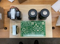
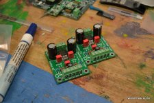
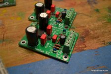
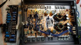
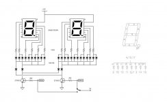
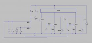
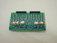
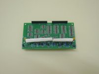
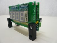
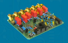
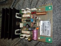
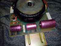
GoldMiniReg aka "GOLD reference regulator". I think it's a commercial product. It has a golden PCB so it must sound good, and a huge TO-247 pass device, so baddass it doesn't even need a heatsink.

goldminireg.jpg

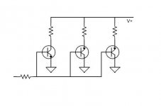
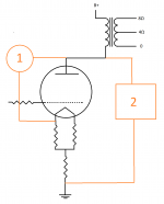
It is definitely a Jung SuperReg clone.

NGRsch02.jpg

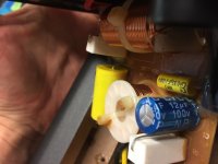
Lots of expensive and oversized parts:

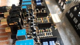
MUR1520G OnSemi "15A 200V Ultrafast 35ns/60ns Recovery Time", with caps in parallel, but no snubber.

OPA134, J170, LM336

One silver mica cap, 9 film caps, probably to distract the eye from the "No Name Shenzen Special" electrolytics.

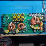
The pass device is a very chunky 2SC5200, NPN 230V 15A, max 150W (hum), probably one of the worst possible choices for this: high voltage device, therefore high Vcesat, but in a regulator you want to use it at low Vce, it has huge capacitance (especially at low Vce), very low fT (30MHz) that it only reaches at high current which won't be the case here, hFe is mehhhhh, etc.

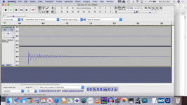
Alright, it's a 5V regulator, I load it with 47 ohms (~100mA). Output ripple:

noise1.png

Huh?

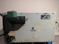
I then discovered my XYTRONIC LF3000 soldering iron used PWM on its heater and apparently it puts out some noise. So it found a new use as a conducted EMI generator.

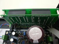
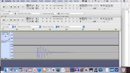
Measuring the input smoothing caps:

noise.png

Yes, there is something (white arrow). I'm not talking about the rectifier spike and associated ringing which fills the whole screen due to no snubber, but about the tiny fur on the trace, that's the noise from the soldering iron. It doesn't look that bad...

Then I compared the amplitude of the noise on the input and the output of the regulator. It was higher on the output. Extraordinary.

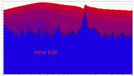
An output impedance sweep with the network analyzer reveals the circuit has an impedance spike close to the frequency of the offending noise, around 300kHz, which means it is unstable. And it will probably amplify whatever noise it picks up, which explains the above.

goldminireg_outz_comp.png

I did more tests with the network analyzer output cable not connected to anything, the stripped end of the coax that I use to inject signal into stuff just lied there in the general vicinity of the regulator... and it managed to pick up 300kHz and reproduce it in the output 😀

An output impedance test with a 10µF MLCC capacitor in the output should be the final nail in this coffin.

goldminireg_outz_comp_10u.png

Verdict: Failure.

Is Ceramic Really Better?

I've always liked robust 6.5" drivers and at the 2019 Capital Audiofest (CAF) they could be found everywhere, in the listening rooms and out in the corridors.
This SB ceramic driver perked my interest but the response looked a lot like speakers I have on the shelf, but cost 3x as much..
Madisound posted the Bromo Kit, with a schematic from SB (I guess), which could be interesting but don't really know if there is going to much of an improvement on previous SF/SB29s builds.

Any thoughts?

btw, the CAF 2021 event is on!

Untitled.jpg

Untitled 2.jpg

Large 1.1 Mono system with 18" woofer and vintage receiver

Hi all,

Some time ago house needed some renovation and during it there was need to take apart one of closet cabinets to reach insulation materials behind it. After project was over there was just empty recess in wall. But there was never urgent need for new cabinet and recess stayed..

This recess face dining area where I have keeped vintage Technics SU-8055 amp with some small bookshelf speakers. I play quite lot internet radio here with my Ocean digital WR-10 internet radio.

Recently when I moved old projects and enclosures to warehouse I noticed that my unused JBL 4645B subwoofer enclosures fit perfectly to this recess when flipped to sides. These big enclosures (8cuft/225L each) could make 1.1 mono system which would be perfectly hided behind sturdy wooden frame which could be covered with white or grey cloth.


I was thinkin about:
Upper 8cuft enclosure (sealed)
*Fane 15-300TC (owned already)
---> HP LR12db at F3

Lower enclosure:
JBL 2240H (already have this also)
---> LP LR24db at Fanes F3

Fane 15-300TC models in 8cuft sealed by having F3 of 59Hz and qtc seems to be way over 0.7 because response is peaking. It could be handled with series cap or Minidsp Nanodigi.

JBL 2240H is not so great choice for 8cuft sealed (I would prefer sealed subwoofer in this project) and its F3 seems to be 98Hz and due to low xmax thinking its not possible to make linkwitz transform for it.

Im searching for 18" woofer which has specs to suit:
*8cuft sealed with F3 that make it useful for subwoofer in this project.
*Keep up with 15-300TC
*Suits for low powered SU-8055 (47W, Damping factor 16 (4 ohm) 36 (8 ohm)

I once read from user Linesource´s post that he prefers 18" woofers with modest Le and Mms, I understood that this was because of lower power needs. But he was suggesting them for stereo speakers and 2pcs per side if remember correctly.

Thisfar my candidate for subwoofer is Peerless FSL-1830R09-08.
It offers F3 of 47Hz in 8cuft sealed.
Peerless by Tymphany FSL-1830R09 - 18" Subwoofer

I think Technics could handle it.

But there is temptation to get more sturdy driver like Lavoce SAN184.03 and convert SU-8055 speaker level signal to line level and drive LAVOCE from Crown amp with Linkwitz transform.
LaVoce SAN184.03 - 18" Subwoofer

I dont know which way to choose with sub..
I would appreciate any suggestions or comments for my subwoofer choices

In search for the LME49713

Hi guys,

Does anyone know where I can find these?
I would like to do some experimentation with them as mixing Amp use.
The values needed for the feedback resistor to get a good frequency response is ideal for what I would need.
Why do good parts go obsolete so fast.....

The frequency response stays almost the same not depending on the gain (It's a current feedback opamp)
So I think it is perfectly suited as a mixing amp on a virtual earth mixbus.
Just have to find some...

High Grid-Cathode Voltage in LTP

Alright folks,

Maybe got a weird one for you today...

I'm working with a typical guitar amp, LTP phase inverter.

Setup:

V_B+: 380V
V_plate: 270V
R_plates: 100k
R_cathode: 680
R_tail: 43k (I've tried 24k to 43k with the same effect)
R_grids: 1Meg
C_input_couple: 22n

When I meter the grid to cathode voltages, I get -1.2V. When I meter the grid voltage (grid to gnd), I get about 55.5V. When I meter the cathode voltage (cathode to gnd) I get about 85V !!!

I can't for the life of me figure out what's going on! I measure the voltage -> where it should be. I measure the differences to ground and BAM, weirdness.

I've swapped tubes and input caps so far. The voltages on the "other side" of the caps is 0V as it should be.

Any ideas? Is this magic, or have I had my head in the chassis too long and am having a huge ol' brain fart?

Thanks in advance!

Orion Cobalt 2100 BJTs

Looks like this was asked before but need to ask again to be more certain. I'd like to repair this amp, but it needs new output BJTs.

Currently using SMW45N10 / SMW20P10.

What are my combinations/options?

IRFP9140 & IRFP140?
IRFP9140 & IRFP150?

I see a place in Florida may still have some IRFP9150 also.

Otherwise if there is no reliable part for this Cobalt 2100, its going to become parts unfortunately. I saw some repair threads where the voltages across emitters didn't look so great/reliable.

https://loudspeakershop.eu - any references?

Greetings, I am looking at a three way SB Acoustics design and I found this Polish shop Głośniki, zestawy montażowe, przewody, wtyki - akcesoria i sprzęt audio - sklep internetowy - LoudSpeakerShop.eu with very reasonable prices. Since I am very careful when I deal with eshops that are not well known and recommended by others I sent them an email asking some product questions but I never received a reply.

I am wondering if any of you have used this shop before for making purchases and what is your buyer's experience.

Regards,

George

BF469, 470, 471, 472 vs. MJE340/350 are ON better?

Hi!

Does anybody have reliable information about MJE340 and 350? I wonder about Ccb, Cbe and Cce capacitance. I wonder also about the transition frequency. The datasheets from ON are very poor in that sense.

BFxxx are 20 years old, have worked fine for but those types are only 2 Watts. Does anybody have anything good (or bad) to say about the ON-types? I'm mostly interested in technical performance, speed, noise, peculiarities.

My application is cascodes for diff input stages and high gain second stages, and of course high output power amps +- 70-100 volts.

B&W Signature 800 upgrade diamond tweeter

I need an opinion from experts on speakers.
I have the sig 800 and I would like to update the tweeter to the new diamond used on the 800D.

Comparing the two service manuals the woofer and midrange have same exact crossover with a slightly different cutoff frequency on the mids but a different network for the tweeters.

Would it work well if I change tweeter and relative crossover for mids and highs?

Would I have any significant benefit by upgrading to that tweeter?
After all I have read all over how this new tweeter improved the performance over the past nautilus series!

Thanks.

Sonic Barrier vs Dynamat for TT

I'm rebuilding a Russco Studio Pro Model B turntable and along with all the usual mods I was thinking of putting a sound deadening material on the bottom of the cast aluminum chassis.

After stripping the chassis for preparation of getting it powder coated I tapped the chassis with the handle of a screwdriver and it rang like a bell.

Doing some searching last night brought up a product from PartsExpress called "Sonic Barrier". It looks nicer and seems like it would be easier to work with.

Any Sonic Barrier users here?

Thanks for any advise.


BillWojo

Build your own tonearm cable

Hi,

What about the idea of DIY tonearm cables ? Few questions are:

1. What should be the ideal wire gauge ?
2. What is the best conductor that can be used ?
3. What should the insulator be made up of ?
4. Do we need to twist them as pairs or can we use them as strands ?
5. Which one is the best: stranded or solid core ?

Please post your ideas/comments....

Best regards,
Bins.

Interest in RJM Audio B-Board Buffer (v1.1)?

Folks:

I am considering hosting a group buy for RJM Audio's B-Board buffer (see (RJM Audio B-Board Project). Richard Murdey (of RJM Audio fame) has graciously provided me with the Gerber files for two versions of his B-Board: (a) version 1.1, which is a unity gain line buffer with a regulated power supply; and, (b) version 2.1, which eliminates the regulated power supply but updates the output stage. I need a few of version 1.1 and would be happy to have extras made if others are interested. If demand for version 2.1 is strong, I could offer that as well.

My guess is that pricing will be about $1.00 (US) per board (so $2 per stereo set), plus shipping and PayPal fees. Domestic shipping would probably be about $5 for padded, uninsured mailers or, if you prefer, $8.30 for insured Priority Mail. That means someone in the US could get two pairs of the boards for under $10. Shipping from the US to the EU is pricey, so if there's interest I'd suggest someone in the EU contact Mr. Murdey and host their own group buy. Alternatively, if someone in the EU wants to act as a distributor, I could have extra boards made (lowering the cost per pcb) and supply the distributor. If there's interest in A/P, I strongly suggest you contact Mr. Murdey and have the boards made locally (saving the cost of shipping the pcbs halfway around the world twice).

Enough of my blathering. Is anyone interested? If so, please indicate which version you want and the quantity. This isn't a firm commitment, just an indicator of likely demand.

Regards,
Scott

First repair; KAF-1030 no power - troubleshooting advice appreciated

Hello guys,

My Kenwood amp just broke down a couple of weeks ago. I loved it so much that I don't want to throw it away, even though my closest prior experience to DIY audio is building a PC. I hope you can help me with troubleshooting. I have a voltage meter at the ready and am ready to fix this thing.

The problem: The speakers don't work and even the power-light at the front doesn't glow up. I can only hear a faint humming from inside the machine. The speakers get 0 sound.

Already checked: the 3 fuses I found aren't burned out.

My question:
How do I start troubleshooting? My idea is to measure the voltage from the power inlet and one step further every time it gives enough voltage. But I have no clue as to what voltage there needs to be at what point.

Instruction manual: https://www.vintageshifi.com/repert...e.php?pdf=Kenwood-KAF-1030-Service-Manual.pdf

Pictures:
An externally hosted image should be here but it was not working when we last tested it.

An externally hosted image should be here but it was not working when we last tested it.

An externally hosted image should be here but it was not working when we last tested it.

An externally hosted image should be here but it was not working when we last tested it.

Mo' Chokes: Building 2SJ28 - 2SK180 Monoblocks

Earlier this year, I built a 2SJ82 source follower amplifier with 2SK82 gain stages. This is an amplifier which I really enjoy, so I decided to build a pair of source follower monoblocks using 2SK180 SITs. For a little change-up, I will use a choke loaded 2SJ28 gain stage instead, and the 2SK180 will be choke loaded as well. The power supplies will be CLC so there will another choke in the mix. So mo' chokes and mo' power. I was thinking of calling this amp Henry or Henrietta, depending on what gender it turns out to be.

I finally completed fabricating the two cases for the monoblocks today, and that for me, is a major milestone. There is still more work to be done on them but it always feels good when all the pieces fit and holes don't need to be enlarged to force things together. I still need to fabricate the mounting angles for the SITs, drill the back panel, and drill holes to mount the electronics but that will only take a couple of days. Then I will start building the electronics.

The interior of the cases are 13.75 inches by 13 inches so I'll have lots of room to arrange things. The heatsinks are Conrad MF35-151.5 (0.21 C/W for 80C rise).


Another name possibility just came to me: Mo-Cho

Attachments

  • 2SK180schem.jpg
    2SK180schem.jpg
    190.7 KB · Views: 1,344
  • Chokes.JPG
    Chokes.JPG
    436.4 KB · Views: 1,299
  • Cases-front.JPG
    Cases-front.JPG
    598 KB · Views: 1,180
  • Cases-back.JPG
    Cases-back.JPG
    694 KB · Views: 1,124
  • Case-interior.JPG
    Case-interior.JPG
    646.1 KB · Views: 1,156
  • Like
Reactions: R-K Rønningstad

Ground Zero GZHA 4120x no audio signal on the filter section

Hi guys,

I'm working on a GZHA 4120X amplifier. I fully restored the power supply section, but now I'm running into trouble with the filter section.

The green 'on' light is not working and there is no audio signal on the speaker terminals. While the power supply section works excellent and the output fets recieve their rail voltage.
The audio signal from all 4 channels don't reach the potentiometers and the switches and seems to stop directly at 2 NJM4558L op-amps (1 NJM4558L per 2 channels)
They don't seem to amplificate the music signal.

NJM4558L DC values
Pin 1: 0.607v (I expect the output to be here)
Pin 2: 0.607v
Pin 3: 1.457v (audio signal from RCA's. Music signal is present)
Pin 4: -13.15v
Pin 5: 1.457v (audio signal from RCA's. Music signal is present)
Pin 6: 0.605v
Pin 7: 0.606v (I expect the output to be here)
Pin 8: 0.071v

Anybody got a clue?

Attachments

  • PHOTO_20210505_154247.jpg
    PHOTO_20210505_154247.jpg
    1.1 MB · Views: 106
  • PHOTO_20210505_154304.jpg
    PHOTO_20210505_154304.jpg
    878.3 KB · Views: 83

Cambridge audio 640a standby on switch intermittent

Cambridge audio 640a amp has intermittent operation of the standby / on switch. Remote control turns it on & off every time. But using the switch on the front, it pulses the input light on off and can hear kind of relay switching noise. I used to be a tv engineer so i can change parts if i need to. Looking at the service manual both the manual switch and the IR receiver seem to go into the same device in separate pins but i don't know what this does. Manual says U5 PIC16C57, but may be a dry joint. Looking for help any any advice.

Which 15"pro woofer? B&C or Faitalpro.....

I am putting together a econowave-esque project. Got a hold of a pair of QSC waveguides, the QSC PL-000446GP 90° x 60° waveguide.

Also working on a pair of DNA-360 compression drivers, from Denovo audio (although I believe these are B&C made...).

The question now is which pro woofer.

I believe I have narrowed the selection:

B&C 15NDL76 B&C Speakers

or the Faital Pro 15PR400 FaitalPRO | LF Loudspeakers | 15PR400


Anyone with more experience than me have any opinions on these drivers?

Thanks!

Diode-Transistor Logic Display (for Wave IO)

Today, digital display is arduino job. But for all those like me who are totaly clueless about code -or is it only me🙄- there is good old DTL! The "code" is hard embedded in a diodes network controlled by transistor drivers. A complete schematic is hard to put on paper. Instead, I've drawn a simplified version. Depended on which transistor you tap the 3V logic level, the number 48 or 96 will be displayed. For all sampling rates from 44.1 to 384kHz it takes 4 digits and 100 diodes... 😱


So, this display won't work with I2C signal! As the title says, it is designed to work with the wave IO usb to I2S converter which provides output for LED indicators. One LED per sampling rate but only up to 192kHz. For 352,8 and 384 it turns on a combination of two LEDs - 88.2+176,4 and 96+192 respectively. It was a challenge to make this work. I used AND gates but I needed to keep the original drivers off -say 96 and 192- when the combined driver -384 in this case- was on. Actually, this part of the circuit is Mooly's work. Basics on transistor drivers I would never had made it without his help! Wave IO provides two more LEDs to indicate " Host Active" and "Audio Streaming". These are written on the copper layer of the PCB an illuminated with LEDs. Three LEDs on one side and two on the other connected in parallel. They also need some kind of diffuser and I found that works very well using two layers of white heatshrink tube, one sleeve firmly attached on the LEDs and then one loosely including them all. See pics. A small diaphragm between the two sides is needed to prevent "crosstalk". It makes a very nice vintage look! The photo is not that good to show this...


It requires an external psu. I designed it to work with 5V and there is an LM7805 on board so the input can be raw DC ~7V min, not much higher. Power consumption varies depending on the sampling rate displayed, from 150mA to a little less than 300mA. Be careful not to pass this current through the usb microcontroler! In case you use the same psu for both, make sure you provide a ground returning path to the psu. I'm using the raw DC before the wave IO regulator and omitted the ground wire of LED outputs.


It consists of two PCBs connected with pin headers. I attached gerber files and BoM for DIY use. Also, I designed a 'generic" version of the PCB, that is ten independent logic inputs, no AND gates, to make it compatible with other possible designs. Choose what you need. In any case, for "wave IO" or "generic" you will also need the "digits" PCB.


That's all I think... Have fun!

Attachments

  • Display Schematic.JPG
    Display Schematic.JPG
    101.4 KB · Views: 279
  • AND Gate.JPG
    AND Gate.JPG
    87.9 KB · Views: 276
  • Drivers.JPG
    Drivers.JPG
    78.2 KB · Views: 262
  • Diffuser.JPG
    Diffuser.JPG
    57.7 KB · Views: 267
  • Display.JPG
    Display.JPG
    64 KB · Views: 258
  • Rear.JPG
    Rear.JPG
    93.4 KB · Views: 226
  • 352,8.JPG
    352,8.JPG
    64.2 KB · Views: 258

Revox B226 Studer A727 repair

I have a Revox B226 that powers up, tray mechanism works good, disk starts to spin up then stops before playing. After extensive forum research I am working my way down the list. Done so far:

Recapped all electrolytics
Reseated all IC’s and ribbon cables
Made small adjustments to the motor spindle Torx bolt
Let the machine warm up over an extended period
Cleaned the laser lens
Going to probe all regulated supply voltages today
Need to replace the L272M in the IC5 position

Some questions:

1) What do you guys use as a replacement for the discontinued L272M in the IC5 position?

2) what are the blue caps of death (BCOD)? Are they electrolytic or the blue non polarized caps?

3) How much of an adjustment are we talking about on the spindle height adjustment torx, 1/4 turn.....?

4) Can I see the eye pattern with a digital o scope? Does this apply if it does a short spin up but won’t start playing?

5) Any other ideas?


Thanks,

George

connecting i2s to dsp enhanced serial audio interface

Hi I am taking my brave first step to the digital domain in diyaudio starting from dsp chips.

Becasue the terms are used differently, I would need some advise on the correct connections on the respective i2s pins (MCLK, LRCK, SCLK, SDATA) to the dsp56362 under the default enhanced serial audio interface mode.

So after some reader I cam to the following conlculsion (--- mean connection)
1. MCLK --- HCKR
2. LRCK --- FSR
3. SCLR --- SCKR
4. sdata --- SDI0, serial data 0 ( this make me scratch my head, there are 4 serial data port, how does the dsp recognise serial data 0 it outputing the correcting signal not the others ports)

For your dsp pdf page 23
Blocked

thanks in advance

What if your power rails are unbalanced

So ... i built this headphone amp and one transistor pair BD139/BD140 were getting very hot ...
There were issues with a magnetic pulse when i turned the power supply off. So i rebuilt the rectifier/regulator and put all the extra diodes to handle transients or backward voltage (discharge). Seems a little better.
The previous board was making 15v and -15.2v - the new one making 15.1/-15.1. Now its not getting what seemed before like thermal runaway (which yes, i accept that's about heatsinks).

So my real question is if this imbalance between +/- could have made the biasing cause more current and therefore heat - or some kind of DC that went away.
All the base were showing about 0.65v +/-

Here is the circuit and I've got a bunch of caps for all the power rails to stabilize (and I run 100 ohms between power to opamp power just because I saw it on a circuit and when I do that my opamps seem to be very stable).

p24_fig1.gif


I also added another filter stage to the rectifier with 3.3 ohm between caps (which I imagine only has 0.3v drop across that resistor on each rail) to reduce the ripple. So maybe that helped with the pre-regulated power that is feeding the output amplification stage with the BD139/140. The original power supply suggested just had 1000uF filter caps now its got about 1200uF and then another 470uF after the resistor and more smaller poly caps. One would think it didn't matter due to the caps at on the headphone amp bypassing all the power rails all over the place ...


I don't have an oscilloscope so I'm limited to a multi-meter and my imagination. Any diagnostic suggestions

DIY custom rack finished

Well, my rack is finished...I wanted to rid myself of an old CRT TV based "component" rack. We have all seen the things at one point, the ones with a square meter sized top, for the biggest of CRT TVs, and the obligatory smoked-glass doors...problem is they take up far too much floorspace, & your gear disappears within. Reading thru the forums here I found a three-legged DIY rack people were creating...so I made my version & reoriented my "modernized" 60s era Leea brand FR speakers.
*Having trouble uploading PIX, got to trouble shoot*


----------------------------------------------------------------Rick...

829B Balance adjustment

I am playing around with the 829B and am trying to address the imbalance between sections without adding a -Vg1 bias supply.

I set up a resistor to zener reference (5.6V) in parallel with a pot to adjust the bias point of one half the tube and adjusted Vg of the low current section up to balance the two halves.

It seems that whether I use a negative bias or positive bias I still end up with the same issue that one tube is going to go into cutoff before the other due to the difference in bias voltage.

It took 1.7V of bias trim to balance the two sections of the tube I am working with which without trim had 26mA in one section and 14.7mA bias in the other.

Any thoughts on this approach over fixed bias?

Attachments

  • 829B_Fixed_n_Cathode_Bias_Photo_.png
    829B_Fixed_n_Cathode_Bias_Photo_.png
    54.9 KB · Views: 168

12" fullrange driver identification

Hello,
For years I thought I'm a good researcher, but it's time to give up. And the delinquents are at attached pictures.

Unknown - Google Photos


My friend bought speakers, probably German made with those, and they're great fullrange. We tried comparable identification with Philips ADs, and many many more, but we can't recognize the manufacturer. It could be PA speaker, or guitar speaker, don't now.

Could you look at pictures, and give any advice or hint, if you've ever seen such drivers, what are those?
Thank you


freeDSP - an open source 2-in 4-out digital crossover board

I want to spread the news about freeDSP (freeDSP | An Open-Source Low-Budget Audio DSP)

This is an effort to develop an open-source hardware platform using the ADAU1701 DSP chip that is similar to the miniDSP 2x4. The main differences include:
  • ability to run at 44.1k, 48k, or 96kHz sampling rate
  • publicly available hardware design (I assume the board's Gerber files will be public)
  • programming done using the SigmaStudio interface instead of the miniDSP GUI
  • lower cost (50 Euro per board)
  • board comes as a DIY kit with thru-hole parts. Any SMD parts will already be soldered to the board.
What you get is a kit that requires assembly, that is less expensive than the equivalent miniDSP offereing, and has greater capabilities than the miniDSP offering (the 2x4). This is not only because it can run the board at a 96kHz sampling rate, but also because SigmaStudio offers a much wider range of DSP processing options compared those available via the miniDSP 2x4 GUI. MiniDSP chose the lower sampling rate and limited DSP architechture for the 2x4 so that it would sit at the low end of their product lineup. With the freeDSP board, all the possibilities that can be supported by the ADAU1701 DSP chip are unlocked through SigmaStudio.

This is a very exciting and superior alternative to the miniDSP 2x4, and I am embracing it 100%.

They are currently accepting names for the first run of these boards at the web site. They need only to reach 20 pcs before they place the first order. If you are at all interested in DSP, this is definitely worth trying.

Attachments

  • freeDSP_board_mockup.png
    freeDSP_board_mockup.png
    127.7 KB · Views: 6,753

Will this linestage work?

Any suggestions on improvement would be great, I know its not going to be perfect.


I drew this up based on the svetlana design using an EF86 strapped as a troide for the first gain stage and I decided to insert a tone circuit and balance control with a bypass switch.
(see 6th Street Bridge: Triode Connected EF86 linestage and headphone amplifier )


This is where it got a bit muddy for me, I am not sure I have got this part correct, its based on the Baxandall design. I get the feeling I may need to insert a coupling cap somewhere in here


Im also looking if the final gain stage can easily be modified to suit an ECC83/12AX7 instead of an ECC88/6922.


While I dont intend to use headphones anytime soon, it would be nice to have it work well with them since im going to the trouble of this build.
The link notes that it really only suits high impedance headphones, I dont know how expensive and/or common these types are.


Anyway, here is the schematic:

Attachments

  • Linestage.png
    Linestage.png
    101.9 KB · Views: 314

Advice needed with a discrete JFET differential to SE input buffer

Hi,

I am trying to do a discrete differential to SE input buffer for my active crossover. After good experience with J113 based buffers, I found this design (CD53_CFP_DiscreteOutputStage.jpg) somewhere on google picture search and adopted it. Two things I would like to improve:

1. Active load for the LTP input. I tried to replace R9/R12 with a current mirror, but had no luck. Could not get a working sinus signal
2. Simple solution to get rid of the output cap C1.

I would be happy for any suggestions.

Regards,
Michael

Attachments

  • CD53_CFP_DiscreteOutputStage.jpg
    CD53_CFP_DiscreteOutputStage.jpg
    102.1 KB · Views: 618
  • Concept_JFET_Bal_SE.png
    Concept_JFET_Bal_SE.png
    33.7 KB · Views: 601
  • Concept_HDAM_CD53.asc
    Concept_HDAM_CD53.asc
    7.7 KB · Views: 89

Martin Logan CLS II with Acoustat MK-121-2A Interfaces

I recently picked up a pair of Martin Logan CLS II but their interfaces have been replaced with the Acoustat MK-121-2A. I also own Maggie MG-IIIa, Maggie MG-3.5R, Apogee Scintilla, and Wilson Watt Puppy 5.1 and I have to say, they may be the best sounding on the list. The previous owner (now deceased) was quoted as saying the Acoustat interfaces are considered better than the original ML interfaces. Have you ever heard of these being installed on CLS? Also, those speakers are supposed to go down to 35hz or so, but they sound a little thin in the bass. It looks like there are 3 taps in the interface selectable for 2,3, or 4 panel electrostatics. I wonder if this is set wrong for the CLS but I have no idea how many "panels" the CLS II have. Any insight would be appreciated!

Phono Cartridge for Thorens TD-166-MKII

Hi,

Just replaced my technics sl221 with Thorens TD-166-MKII that came with Grado Prestige Red cartridge + ortofon 2m red.
I really don't satisfied from the sound...i listened it while it haf a different cart.

First of all: what kind of cartridge suites this arm?

Secondly: I would love to have a recommendations for a good budget cartridges for that model.
Up to 100$ / 85 eur / 75 gbp.

Thank you 🙂

Bextrene surround replaced w Foam...does crossover need changing ? ESS AMT 1B

I recently was gifted a set of ESS AMT 1B speakers , the woofer was designed for Bextrene surrounds. The previous person replaced those surrounds with foam instead of Bextrene or rubber...
Since the crossover was designed for the bextrene characteristics, shouldn't the crossover also have changed to now accommodate the woofer with foam ?
I also have AMT 1A speakers which originally came with foam surrounds, the crossover in that model is significantly different than the AMT 1B crossover.
Any suggestions ? Do I now need to go with the same crossover as the AMT 1A?
Any thoughts on the topic are appreciated
Thanks

LP mat/platter interface

I have been conducting some simple experiments and measurements on various mat/platter construction materials. My basic test is an impulse test of dropping a 15.5 mm diameter glass marble on the surface of a sacrificial LP, with a peripheral ring and centre weight in place, total mass ~ 2 kg. I measure the rebound as % of the fixed drop height (50 cm). Listed in order:

Carbon graphite (Boston Audio Mat 2) 5%
Cork/Rubber (DIY) 15%
Felt (Rega) 15%
Carbon Fibre/Stainless steel (TTW Ultimat) 40%
Carbon Fibre/Copper (TTW Ultimat) 45%
Hard Rubber (Thorens, Technics) 50%
Sorbothane (Platter Matter) 50%
Delrin/Stainless steel 80%

I am only really interested in the extremes, which are both surprising to me. The carbon/graphite rebound is like throwing play dough on the table. One bounce and it is rolling. The Delrin/SS is the bigger surprise. The platter is 11 kg with label recess machined into the Delrin.

One of these sounds clearly superior with LP replay, to all others, in my system. Here is my take on why.
The signal source is the record groove. The function of the groove is to move the stylus accurately for conversion to an electrical signal. To this end the groove motion should remain uninfluenced by extraneous inputs. In moving the stylus, the groove will be subject to reaction forces that push back into the groove. The impulse test indicates the extent to which the LP interface rejects (vertical) reaction forces.
The higher bounce examples indicates less energy into the LP, more returned to the dropped ball.
In the LP replay situation, this means more energy into the cartridge/tonearm/plinth.

I am prepared to be completely wrong in my analysis, however I am trying to make sense of what my ears are telling me.

The first plot is the carbon graphite mat, with the second bounce at approx 0.2 s after the initial impact. The main mode frequency is approximately 19 Hz.
The second plot is the Delrin/SS platter. The principal damped resonance is at 12 Hz and is most likely the tonearm/cartridge resonance.
It is quite apparent that the second impulse plot decays much more rapidly than the first although the first is at a lower amplitude which is not apparent because of the normalisation.
My ears/brain seems to prefer the rapid decay version.

Attachments

  • Screen Shot 2021-01-24 at 2.21.01 pm.png
    Screen Shot 2021-01-24 at 2.21.01 pm.png
    339.3 KB · Views: 568
  • Screen Shot 2021-01-24 at 2.21.12 pm.png
    Screen Shot 2021-01-24 at 2.21.12 pm.png
    358.2 KB · Views: 563

  • Locked
Lousy GE bulbs! - Warning!

Yesterday (May 2, 2021) at Lowes, I picked up a 2-pack of GE T8 type LED tubes to replace the failing 48" flourescents over my workbench.
The Lowes website Item #2565452 Model #93129276
On the package they're marked as LED 83CCT15ET8GH-LT2PK "Color Select"
They also note to use them only with electronic ballasts.

These have a 3 position slide switch on one end to select 3 different color profiles - I liked the bright setting best.

Last night, they worked great - for the few hours I used them.


Because today, upon turning them on, both tubes popped, barely glowed, and made the electronic ballast whine like it was overloaded. (SMPS typical overload whine)
They're plain GARBAGE! - made in china JUNK!
Putting in the older flourescent tubes, the fixture worked fine - so it's not a ballast issue.


I went to Lowes site and gave a nice juicy One Star complaint, (among the MANY other complaints) and now have to go back and return the damn things - something I should not have to be bothered with.


I'll get something else that lasts.

Unbalanced line to balanced XLR line?

I am confused about what I need to do to go from an unbalanced line connector to a balanced XLR line connector.

I am not looking for ultra-pro audio performance, just the basics. I am trying to output 5.1 / 7.1 sound over XLR from a $32 StarTech USB converter box that only has 1/8" stereo output connectors.

This is for movie-like surround sound in a gymnasium using powered XLR speakers.

A direct wire is probably good enough if I keep the unbalanced part of the cable as short as possible, but it seems that an autotransformer is needed to properly center-tap the ground wire for the twisted pair XLR cable.

Is just a straight 1:1 ratio center-tap audio autotransformer / balun needed to properly balance the XLR output?

I am trying to find a part that I can look up on DigiKey / Newark, or hopefully a preassembled cable with the autotransformer already included.

Measuring 300B plate voltage

I watched a video that made me reevaluate life's meaning..
Well, not really lol.. But, it sure confused me on how B+ should be measured for figuring tube bias on a 300B.

The attached shows my dilemma.
I assumed B+ should be measured from #2... After the video, I now think #1 might be (EDIT: I mistakenly said wright) wrong

May be the cathode resistors are lifting the entire tube enough above ground, that the plate might not know (or care) about the voltage #2 measures (bird on a wire).

Before I make any more assumptions, I figured I should just ask the experts!

Attachments

  • B+ From.png
    B+ From.png
    32.1 KB · Views: 606

Ultra Fast diode rectifier and PT snubber on guitar amp

Hi everyone,

I'm new to the forum but a long time reader, I write this post because I would like to see if someone can give me a good advice 🙂

I have a Fender Vibro-King, I love its sound but I'm always disappoint about it's noise floor comparing to my other amps. The noise it's like a 100hz hum, maybe it's part of its design... yes I can live with it (I play it since 2012) but recently I read some posts here regarding UF diode vs standard and the UF seem from what I've read less noisy especially if paired with a snubber circuit.

I read that the best result is using four UF4007 in the full wave rectifier, and before it, on the secondary of the PT the snubber (47ohm resistor and 22nf 1500V cap between secondary).

I would like to try it, but I have a question watching the schematic. Here I attached it...

The best place for the snubber is right before the full wave rectifier before the standby switch? Before the 8200uf caps? Or 2 snubber circuits from both the secondary leads to the Central Tap?

What do you think? And do you think it's a good idea?


Thank you very much to everyone!

Attachments

Hammond 274BX wiring question

Hello all.
I'm putting together a bench test of my SSE. I'm starting by connecting up the Hammond 274BX power transformer, but I have a question before I proceed.

The green wires, red wires, red and yellow wire, and yellow wires are all very straightforward, and I have the connected to the appropriate spots on the PCB. However, I'm not entirely sure about the remaining wires.

Here are the remaining unconnected wires:
White
Gray
Black
Yellow+Black
Green+Yellow

I'm not clear on which of these should be connected to power. Which one is live, and which is neutral? The top of the transformer says "WHT - GRY: 115V 60Hz"
Does that mean white is live and gray is neutral?

The label also says "WHT - BLK: 125V TAP".... I'm not sure what that means. I'm in the US which means 115V is the correct option, yes?

F.S. Mark Audio and Fostex drivers.

Good Evening everyone..I hope everyone is safe. I have sold aot of driver's but, I still have more to sell..I have mostly current driver's and any used or older drivers have been sold..So please e mail me if your interested? I can work out a price with shipping I can send pictures and a price am thinking of..All drivers are shipped in pairs..All drivers are brand new and never used or tested..Just opened to make sure there is not visible damage to the drivers. Thanks Jeff

Why not just shoot a coat of paint on that tonearm?

I just took receipt of a used Jelco ST-250, which is the best tone arm I'm ever going to own. But it's painted black, which probably appeals to juveniles who like monster robot movies but not to me.

What's the worst thing that could happen if I just gave the thing a nice coat of Duplicolor in an actual human-friendly tone of some sort? If you are familiar with Duplicolor you know that it is mostly thinner with rather little paint in it. I could mask sensitive areas. It doesn't seem like an impossible thing to do, if you're crazy enough to want to...

Cheap parafeed transformer for 300B electrostatic headphone amplifier

Hello guys,

I have a gyrator at the top of a 300B tube and am looking to hook up a parafeed cap to a cheap 1:1 or step-up transformer that would be used to produce the balanced drive for electrostatic headphones.

Anyone know how I would go about determining specs on a transformer suitable for electrostatic headphones? As the transformer is hooked up parafeed, it doesn't need a gap for DC. I was thinking something cheap such as the Hammond 1182G117 toroidal, however here are the measurements that Hammond sent me for this transformer:

"The results at 60Hz are as follows:
Primary connected for 120V is 42.4H at 1V 60Hz.
Primary connected for 240V is 112H at 1V 60Hz.
The leakage inductance connected for 120V is 1.68H at 1V 60Hz.
The leakage inductance connected for 240V is 7.13H at 1V 60Hz.
Leakage inductance at 1kHz is 17.24mH"

Little cone Peerless Tweeter with a 10uF capacitor:how power it takes from the ampli?

Hi guys!
I already know my question is very strange, but being a newbie, I've this curiosity.
If I have a 12 watt power amplifier (at 4 ohm) and a little cone Peerser tweeter (MT-25 HFC/4 ohm) with a 10uF capacitor connected to it, approximately how many watt I'm leading to the tweeter in question?😕
Sorry again for this stupid question.🙁
Thank you in advance for your patience:yes:
Best Regards.

Up-grading this old amp circuit board!

Hi Guys!!!😱
I'd like to upgrade this amp circuit board! (This is one of the two amp modules!)
The pink Facon capacitor you can see and the other smaller black capacitor, are both 220 uF...the pink Facon has 50 V, whilst the black one has 16 V.
I want to replace them with two bigger capacitors (for example with two 470uF) but I've a dubt (I'm a newbie, so please forgive me if Im wrong!😕)
The Power supply unit has a stabilized current circuit (you see it in the picture)...so could this capacitors up-grade is a problem for the amplifier?😕
Thank you!
Regards😉

Attachments

  • imperial amp module.jpg
    imperial amp module.jpg
    206 KB · Views: 323
  • imperial power supply.jpg
    imperial power supply.jpg
    213.1 KB · Views: 326

Recapping a stabilized current power supply!

Hi guys!
I would to recapping this old recapping stabilized current power supply from a vintage amplifier.
As you can see in the picture, there are three pink electrolitycs capacitors: the smallest ones are 3300uF 25 V, whilst the biggest one is 6000uF 32V.
I would to replace them with three capacitors with a bigger capacitance...but I repeat, it's a stabilizer current power supply board.
As I always say here, I'm just a newbie...so my question is: is this capacitors up-grade possible or could it a problem in a similar stabilizer current circuit board?
Thank you for your patience and kindness:worship:
Regards!

Attachments

  • imperial power supply.jpg
    imperial power supply.jpg
    213.1 KB · Views: 200

[Amplifier IRS2092 / IRFB4227] HYY-01 questions

Hi amigos,

I wonder if someone has already tested this HYY-01 class D amplifier, double Mono board.

This is a 2X250W class D amplifier based on IRS2092 / IRFB4227.
I read some really good opinions on the web about it but I would like to know a bit more.

- what about speakers protection ? Anti Pop @ startup ?
- what is it worth compared to the TPA3255 ?
etc

Maybe someone can help with these pictures :

HYY10.jpg

HYY2.jpg

HYY1.jpg

HYY12.jpg

How to Learn Basic Code

this inductor is removed from the car amplifier. The consumables you see are worth 150uh .. But I could not find the code of the kernel. I want to learn to order. Some are brown and some are brown-white. How can we find out what happened?

Attachments

  • 181893701_900997557145939_7791458822907340251_n.jpg
    181893701_900997557145939_7791458822907340251_n.jpg
    35.6 KB · Views: 125
  • 182624752_287847386352735_4372483609783960886_n.jpg
    182624752_287847386352735_4372483609783960886_n.jpg
    73 KB · Views: 120
Projects by fanatics, for fanatics
Get answers and advice for everyone wanting to learn the art of audio.
Join the Community
507,753
Members
7,886,727
Messages

Filter

Forum Statistics

Threads
406,157
Messages
7,886,727
Members
507,753
Latest member
ayodej