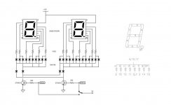
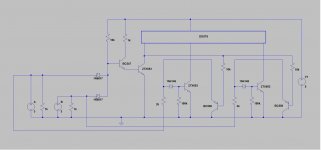
Today, digital display is arduino job. But for all those like me who are totaly clueless about code -or is it only me🙄- there is good old DTL! The "code" is hard embedded in a diodes network controlled by transistor drivers. A complete schematic is hard to put on paper. Instead, I've drawn a simplified version. Depended on which transistor you tap the 3V logic level, the number 48 or 96 will be displayed. For all sampling rates from 44.1 to 384kHz it takes 4 digits and 100 diodes... 😱
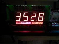
So, this display won't work with I2C signal! As the title says, it is designed to work with the wave IO usb to I2S converter which provides output for LED indicators. One LED per sampling rate but only up to 192kHz. For 352,8 and 384 it turns on a combination of two LEDs - 88.2+176,4 and 96+192 respectively. It was a challenge to make this work. I used AND gates but I needed to keep the original drivers off -say 96 and 192- when the combined driver -384 in this case- was on. Actually, this part of the circuit is Mooly's work. Basics on transistor drivers I would never had made it without his help! Wave IO provides two more LEDs to indicate " Host Active" and "Audio Streaming". These are written on the copper layer of the PCB an illuminated with LEDs. Three LEDs on one side and two on the other connected in parallel. They also need some kind of diffuser and I found that works very well using two layers of white heatshrink tube, one sleeve firmly attached on the LEDs and then one loosely including them all. See pics. A small diaphragm between the two sides is needed to prevent "crosstalk". It makes a very nice vintage look! The photo is not that good to show this...
It requires an external psu. I designed it to work with 5V and there is an LM7805 on board so the input can be raw DC ~7V min, not much higher. Power consumption varies depending on the sampling rate displayed, from 150mA to a little less than 300mA. Be careful not to pass this current through the usb microcontroler! In case you use the same psu for both, make sure you provide a ground returning path to the psu. I'm using the raw DC before the wave IO regulator and omitted the ground wire of LED outputs.
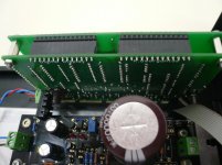
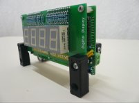
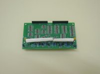
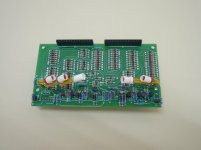
It consists of two PCBs connected with pin headers. I attached gerber files and BoM for DIY use. Also, I designed a 'generic" version of the PCB, that is ten independent logic inputs, no AND gates, to make it compatible with other possible designs. Choose what you need. In any case, for "wave IO" or "generic" you will also need the "digits" PCB.
That's all I think... Have fun!
So, this display won't work with I2C signal! As the title says, it is designed to work with the wave IO usb to I2S converter which provides output for LED indicators. One LED per sampling rate but only up to 192kHz. For 352,8 and 384 it turns on a combination of two LEDs - 88.2+176,4 and 96+192 respectively. It was a challenge to make this work. I used AND gates but I needed to keep the original drivers off -say 96 and 192- when the combined driver -384 in this case- was on. Actually, this part of the circuit is Mooly's work. Basics on transistor drivers I would never had made it without his help! Wave IO provides two more LEDs to indicate " Host Active" and "Audio Streaming". These are written on the copper layer of the PCB an illuminated with LEDs. Three LEDs on one side and two on the other connected in parallel. They also need some kind of diffuser and I found that works very well using two layers of white heatshrink tube, one sleeve firmly attached on the LEDs and then one loosely including them all. See pics. A small diaphragm between the two sides is needed to prevent "crosstalk". It makes a very nice vintage look! The photo is not that good to show this...
It requires an external psu. I designed it to work with 5V and there is an LM7805 on board so the input can be raw DC ~7V min, not much higher. Power consumption varies depending on the sampling rate displayed, from 150mA to a little less than 300mA. Be careful not to pass this current through the usb microcontroler! In case you use the same psu for both, make sure you provide a ground returning path to the psu. I'm using the raw DC before the wave IO regulator and omitted the ground wire of LED outputs.
It consists of two PCBs connected with pin headers. I attached gerber files and BoM for DIY use. Also, I designed a 'generic" version of the PCB, that is ten independent logic inputs, no AND gates, to make it compatible with other possible designs. Choose what you need. In any case, for "wave IO" or "generic" you will also need the "digits" PCB.
That's all I think... Have fun!
Attachments
Last edited: