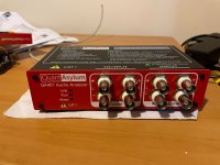
Crestron 16x60 Mod Project: 12V triggerd, Bridgeable to 5x200W/6x60W
I have just completed modifying my Crestron 16x60 to have 5 8 ohm bridgeable channels.
The amplifier is bridgeable using a simple toggle switch without the need for their external bridge modules. I did this by changing the amplifier boards to match the exact circuit that they use on their bridgeable 2x60 amplifier!
I have been looking at Crestron amplifiers for a while now given that they have so many channels and are made by ATI. In the past I had modified a 2x60 amplifier to work without cresnet just using an external 24V power supply.
This modification to the 16x60 goes much further in a lot of ways. It changes the system to fully run on a 12v trigger. 12V Trigger Modification details:
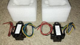
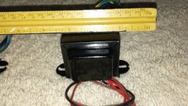
The main relay was replaced with an equivalent 12V version.
The crestron control board was removed and replaced with a 12V trigger via a 3.5mm mono connector (one or the other can be used, they aren't intended to be used at the same time). This is connected to the main relay via a small custom PCB. The amp still requires a 12v trigger input in order to turn on because it has no standby transformer of its own. Alternatively I also added a DC input jack so that a 12V wall wart could be used instead of the 12v trigger.
.jpg")
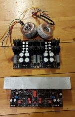
Due to the cost of replacing all of the output board relays with 12V relays they were removed and replaced with 20ga copper wires. The relay control and output monitoring board was also removed which simplifies things and gives more space. Many amplifiers such as my Adcoms don't use output board relays, this can result in a small power on pop but is not a problem.
I suppose I could have left the 24v relays there and could have made them work via a 12v trigger if I was willing to use both a 24V wall wart and add a relay to switch the 24v input with the 12v trigger. For my use model I just removed the output board relays instead but in retrospect it required a lot of desoldering and it might have been easier to add the extra relay and just deal with the wall wart.
.jpg")
The Bridging Idea
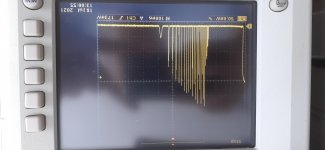
While the amps will probably drive 80watts or more to each channel before distortion I was curious to see if they couble be bridged...
Bridging it pairs channels (which are already on a shared board) and makes the amp much more useful in a home theater environment giving it a great deal of power on 5 channels with 6 channels left at 60w to drive surround or atmos speakers. This amplifier can now be used to handle 7.4.1 atmos all in one package.
My custom Crestron 16x60 can now be configured the following ways:
16x60, 2x200@8ohm/12x60, 3x200@8ohm/10x60, 4x200@8ohm/8x60, 5x200@8ohm/6x60
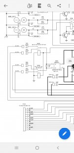
The Crestron 2x60 amplifier is exactly the same schematically as the 12x60 and 16x60 crestron amplifiers except it has one channel per amplifier board instead of two and it is bridgeable. The bridge feature turns out to just be a switch on the input board along with a feedback resistor.
Bridged Specs for the 2x60 are:
Output Power 20Hz to 20kHz, both channels driven at rated THD:
200 watts at 8 ohms bridged
Power Bandwidth 3Hz to 50kHz, +0/-3dB
Total Harmonic Distortion (THD) ≤0.03% at full power
The 16x60 is actually listed as 220W when bridged with external CNXBRMO modules but they specify to only bridge 4 channels. I bridged 5 channels and don't see this as an issue for home theater where it is very very rare to power more than 3 channels at full power. Rather than claiming 220W it seems more reasonbale to expect 200W given that it is using the bridge circuit from the 2x60 amplifier. I made every attempt to keep my addon board very compact to emulate the 2x60 design.
Bridge Module Addition/Modification Method
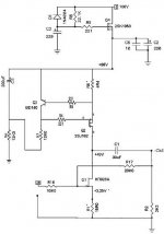
I found an article on Elliot Sound Products describing project 20:
Simplest Ever Bridging Adapter for Amplifiers
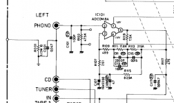
I was curious and discovered that this is EXACTLY what crestron did on the 2x60 amplifier except the crestron has input filter capacitors on both the non inverting and inverting inputs.
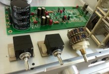
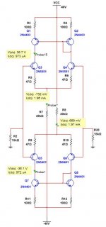
I duplicated the circuit from the 2x60 on this board:
The top pin of the connector is the output to the bridge switch from the 28k feedback resistor that comes from the positive phase amplifier output.
The bottom pin of the connector is the input from the bridge switch which connects to the top pin.
The two capacitors connect in parallel from the 1k resistor to ground and the input (bottom pin).
The white jumper wire on the left connects the square capacitor output to the inverted input of the bridged amp.
The white jumper wire on the right connects to the input side of the electrolytic capacitor.
The outputs of the capacitors connect to the bottom left pin which goes directly to the inverted input of the negative phase amplifier.
.jpg")
.jpg")
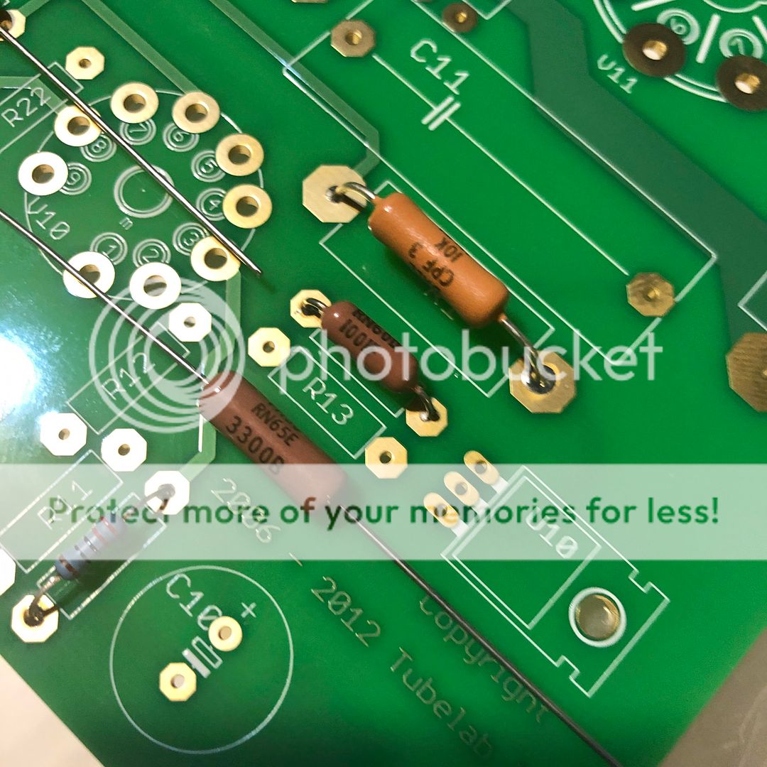
I desoldered and reused the input capacitors (C8A/C9A) from the 16x60 inverting input (the 1k input resistor R14A can also be resused). I then added a high quality 1% 28k resistor to the circuit as the only new component other than the board/wires/switch. The 2x60 amplifier has this resistor on each amplifier board (even though only one uses it) so that the boards are interchangable.
Note that instead of buying 28k resistors there are many of them on the output sampling board that is not needed for a standalone amplifier. This was one of the boards that I removed so they could have been stolen from that board.
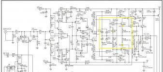
Note that I chose to modify channel A on this board which is the Left channel to stay with the convention of having the Right channel be the positive side of the bridged amplifier. This picture shows the green board version of a 16x60 board which was my prototype where the yellow board version has a slightly different layout and component naming. The differences are very small for the most part. The yellow board also uses different output devices on the amplifiers which surprised me.
The red wire is from the ouptut of the Right channel to the feedback resistor on the bridge circuit. The board already has a via there to go to the other side of the board so I simply sucked out the solder and added the wire through the via (soldering it on both sides of the board).
The 1k resistor is connected to ground and if the bridge circuit is not enabled it connects GND->1k->Input Filter->Inverting Input.
.jpg")
The board connects to Ground via the top connection where C9A was removed from the board. The right side of R14A goes to the inverting input of the amplifier. The board connects to the other side of those components just to hold it in place. There is no connecto to the board accross C8 but I filled in the vias with solder just to make the best possible electrical connection back to ground.
The changes to the board can easily be undone if desired.
.jpg")
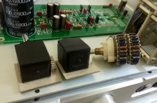
The addon board is then soldered to the back side of the amplifier board using 4 header pins (which happen to align close enough to work well).
.jpg")
I then drilled holes on the back panel of the 16x60 to add a DPDT switch. The 2x60 uses a 3 position switch such that it supports Stereo, Bridged, and Summing (the right input also feeds the left amplifier in dual mono mode). The switch is directly on the input board of the 2x60. I got a deal on some 2 position switches so I skipped the Summing (dual mono) configuration.
I must say that it is CRITICAL to use the best switch you can find. I initially experimented with some ebay switches and found that they added cross channel distortion when used. I had to buy top of the line ALCO switches to eliminate the noise. Once I did that there is no extra cross channel distortion from the switch.
.jpg")
To connect the switch I de-soldered the ground pin from the left RCA input and put the ground connection in the same circuit board hold with it and re-soldered it and connected the other end to the switch. For input grounding I simply soldered directly to the back side of the RCA connector (which is a very easy and robust solder point).
I then used a twisted pair wire back from the switch to the bridging addon board.
The good thing about the 2x60's bridge circuit design is that if the switch is open then it is as if the bridge module isn't there, it only connects the feedback resistor when the switch is in bridge mode. I actually have 6 modified boards in my amplifer but one of them isn't connected and it works as normal.
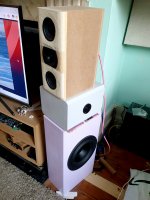
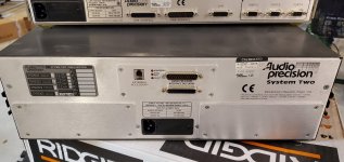
New back Panel:
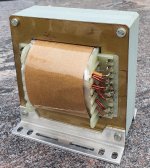
I originally drilled holes to add bridging modules to all 8 boards but then realized that I only need 5 channels to be bridged. I plugged the holes with stainless hardware. It is possible to rearrange the boards but I found it best to distribute the bridged channels accross the two torroid transformers.
I need to redo the labels with my label maker and get them on squarely at some point.
.jpg")
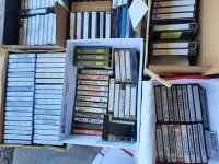
Removed components:
Bag of 24v output relays
Original 24v main relay
Crestron Control board
Output board (and wires) for crestron controller power monitoring.
Output wires from the distortion detect to the crestron board.
.jpg")
-Rich


