I have the following question:
When a pentode is working in triode mode (and in the case where the suppressor grid is not internally connected to cathode) which is the best way to connect the suppressor grid, to anode or to cathode?
Thinking of this, my mind says that a connection to anode seems to be better, as there is no slowing down of the electron beam to anode.
In particular, I'm interested in getting some advice regarding the Russian 6J9P-E pentode. This tube has its pin No. 8 connected both to the suppressor grind and an internal shield. So, what is the best connection of pin 8 in triode mode?

Big thing to worry about with anode connection of the 3rd grid is that it may draw significant current and then get burned off, since it's a fragile element. That ends the tube's life. I am not sure if that's a concern or not, as I haven't experimented with it. If you want to do that, monitor the grid's current under all usage conditions and verify that it stays within safe levels for that grid.
Big thing to worry about with anode connection of the 3rd grid is that it may draw significant current and then get burned off, since it's a fragile element. That ends the tube's life. I am not sure if that's a concern or not, as I haven't experimented with it. If you want to do that, monitor the grid's current under all usage conditions and verify that it stays within safe levels for that grid.
That's something I had never thought about. Your point is reasonable.
I will check this out to see if there is significant current draw from the suppressor grid.
Thank you.
It makes essentially no difference either way. Do whichever is most convenient given the pinout. (Use a 100R stopper resistor to take care of any current concerns)When a pentode is working in triode mode (and in the case where the suppressor grid is not internally connected to cathode) which is the best way to connect the suppressor grid, to anode or to cathode?
Big thing to worry about with anode connection of the 3rd grid is that it may draw significant current and then get burned off, since it's a fragile element. That ends the tube's life.
Not in my experience. That's the screen grid. If you burn off the suppressor it just becomes a tetrode complete with a kink at low plate voltages, no?
This question gets asked every so often.
Suppressor Grid tied to plate and not ground
Tubes
Tube DIY Asylum
pentodes connected as triodes | GroupDIY
There's probably more out there.
--
Suppressor Grid tied to plate and not ground
Tubes
Tube DIY Asylum
pentodes connected as triodes | GroupDIY
There's probably more out there.
--
This question gets asked every so often.
Suppressor Grid tied to plate and not ground
Tubes
Tube DIY Asylum
pentodes connected as triodes | GroupDIY
There's probably more out there.
--
Very thorough and useful reference list, rongon.
Thank you very much!
I'm starting studying...
I saw a schematic and working amplifier published . . . which tied the Plate, Screen Grid, and Suppressor Grid of an EL34 all together.
It was the single ended 'Randall Amplifier' that was a group project at San Francisco's Randall Museum.
One Electron Amplifiers
It was the single ended 'Randall Amplifier' that was a group project at San Francisco's Randall Museum.
One Electron Amplifiers
This is obvious. G3 is required in pentode to eliminate anode current kink that takes place in tetrode. When G2 is connected to anode, no tetrode operational exist anymore. Therefore no need to connect G3 to cathode.
This is obvious. G3 is required in pentode to eliminate anode current kink that takes place in tetrode. When G2 is connected to anode, no tetrode operational exist anymore. Therefore no need to connect G3 to cathode.
That's exactly what my sense tells me. And, as smoking-amp writes in a post sited here:
Suppressor Grid tied to plate and not ground
"Connecting g3 to the plate (also g2) for triode mode will give just a bit lower plate impedance than g2 only to plate for triode mode. One thing possibly useful is that less current will be reflected back to g2 with g3 positive..."
Meanwhile, trying to find out which connection sounds better, I conducted yesterday a direct A-B comparison, using a switch to change the connection of G3 from anode to cathode. My conclusion is that tying G3 to anode sounds clearly better. So, I will stick to this configuration.
Thank you all for your help.
kenev,
Sounds better with Anode/G2/G3 tied together . . . Great!
What tube type did you use for the test? . . . 6J9P-E pentode?
What is your Anode/G2/G3 voltage when they are tied together?
Is it possible that other tube types might not sound better with G3 tied to the Anode.
Other Tube's Mileage May Vary?
Last edited:
kenev,
Sounds better with Anode/G2/G3 tied together . . . Great!
What tube type did you use for the test? . . . 6J9P-E pentode?
What is your Anode/G2/G3 voltage when they are tied together?
Is it possible that other tube types might not sound better with G3 tied to the Anode.
Other Tube's Mileage May Vary?
As I mentioned in my first post, I'm referring to the Russian pentode 6J9P-E. Of course, this may not apply to every pentode, but it is very simple to check which connection sounds better.
Hi kenev,
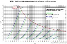
since the (small) g3 surface area is added when connecting g3 to anode instead to cathode, you get a little bit more transconductance. The exact amount depends on several factors of the g3 geometry and position relative to the anode.
Usually the transconductance is upped by about 5 .. 10%. This is well within tube manufacturing tolerances; not to speak tube wear (in the opposite direction, of course).
If somebody says that it sounds "better" connected this way, the circuit should be blamed, since it obviously doesn´t deal gracefully with tolerances of a few % transconductance.
Exemplary plot from my ETF paper attached, which was mentioned somewhere in this thread. Don´t mind it is a small signal pentode - the same effect holds true for power tubes.
Kind regards, Tom Schlangen
Attachments
Hi Tom,
Thank you for the information provided. I have read your presentation, but I don't recall seeing the diagram you posted. Anyway, maybe I missed it.
Could that difference in the perception of sound be attributed to the difference of transconductance? Why has the circuit to be blamed? I'm talking about only slight differences, having the sense that I prefer g3 tied to anode.
Regards,
Evangelos
Thank you for the information provided. I have read your presentation, but I don't recall seeing the diagram you posted. Anyway, maybe I missed it.
Usually the transconductance is upped by about 5 .. 10%. This is well within tube manufacturing tolerances; not to speak tube wear (in the opposite direction, of course).
If somebody says that it sounds "better" connected this way, the circuit should be blamed, since it obviously doesn´t deal gracefully with tolerances of a few % transconductance.
Could that difference in the perception of sound be attributed to the difference of transconductance? Why has the circuit to be blamed? I'm talking about only slight differences, having the sense that I prefer g3 tied to anode.
Regards,
Evangelos
- Home
- Amplifiers
- Tubes / Valves
- Pentodes in triode mode: suppressor grid connection