Been tossing around the idea of building a tapered array for a while now. I can't find much info on this subject aside from various attempts made by other hobbyists and would like to learn more before potentially wasting a lot money.
My main objective is to avoid outboard DSP with this. Yes, I'm aware of the potential costs and complexity pulling off a passive network to achieve this. Please don't beat me down on this. The reason I have for wanting to go passive is to keep the entire design analog to preserve the signal path. Im potentially open to active analog networks, but really would prefer to keep it all passive. I'm ok with losing some efficiency if I can pull it off passively.
There are 2 types of designs I'm looking at -
1 - Tapered FR array with smaller drivers (Visaton B80) + progressive LP filtering moving away from the array center in an attempt to avoid HF combing, although this may defeat benefits of a large array(?). I've heard the B80 and love how it sounds as a limited low end driver. It sort of reminds me of the Scan Speak 10F8414, just all around smoother and handles quite a bit of power, so it can play pretty loud within its other limitations.
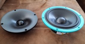
2 - Tapered array with tweeter on center axis and Scan Speak 18W-5537G-01 midbass drivers, acting as a 2 way MTM in the array center @ listening axis and progressive LP filtering to outer drivers moving away from the array center. The midbass drivers are an OE version made for Thiel that I purchased as a bulk quantity online. They are beautiful PP cone drivers with TS specs optimized for a sealed or large vented enclosure. Specs are - Qts .49 / Fs 41Hz / Vas 23 ltrs / 87-88 dB@1W (driver not broken in yet). As a tweeeter, I chose the Morel CAT378 because of how it sounds, can deal with a lower HP frequency and has a waveguide which moves the acoustic center back close to that of the midbass drivers.
I'm open to any creative and helpful suggestions.
My main objective is to avoid outboard DSP with this. Yes, I'm aware of the potential costs and complexity pulling off a passive network to achieve this. Please don't beat me down on this. The reason I have for wanting to go passive is to keep the entire design analog to preserve the signal path. Im potentially open to active analog networks, but really would prefer to keep it all passive. I'm ok with losing some efficiency if I can pull it off passively.
There are 2 types of designs I'm looking at -
1 - Tapered FR array with smaller drivers (Visaton B80) + progressive LP filtering moving away from the array center in an attempt to avoid HF combing, although this may defeat benefits of a large array(?). I've heard the B80 and love how it sounds as a limited low end driver. It sort of reminds me of the Scan Speak 10F8414, just all around smoother and handles quite a bit of power, so it can play pretty loud within its other limitations.
2 - Tapered array with tweeter on center axis and Scan Speak 18W-5537G-01 midbass drivers, acting as a 2 way MTM in the array center @ listening axis and progressive LP filtering to outer drivers moving away from the array center. The midbass drivers are an OE version made for Thiel that I purchased as a bulk quantity online. They are beautiful PP cone drivers with TS specs optimized for a sealed or large vented enclosure. Specs are - Qts .49 / Fs 41Hz / Vas 23 ltrs / 87-88 dB@1W (driver not broken in yet). As a tweeeter, I chose the Morel CAT378 because of how it sounds, can deal with a lower HP frequency and has a waveguide which moves the acoustic center back close to that of the midbass drivers.
I'm open to any creative and helpful suggestions.
Better midrange performance with smaller drivers coupled with wide dynamic range. Ive tried the compression driver thing and was never happy with the sound signature it provides, especially in the very top end of treble range. A large 3 way would work, but i find the bass and lower midrange more even and balanced with multiple smaller drivers. Basically to my ears, a bunch of smaller drivers tend to sound the same at both lower and higher volume levels, which is what I'm also after. A proper array would give me more even near and far-field response in my listening location, which is a semi open medium sized room with high vaulted ceilings.
This thread has some passive CBT array crossover ideas:My main objective is to avoid outboard DSP with this. Yes, I'm aware of the potential costs and complexity pulling off a passive network to achieve this.
Passive Loudspeaker Delay
Posts #4, 12, 15 get into the guts.
Last edited:
This thread has some passive CBT array crossover ideas:
Passive Loudspeaker Delay
Posts #4, 12, 15 get into the guts.
Wow, that's great info - thanks!
The auto former circuit is an interesting way to attenuate the driver groups. I intend on keeping the power distribution fairly even for the most part aside from the obvious power tapering caused by the bandwidth being decreased gradually moving away from center.
The staggering of L + C values are predictable for a curved array. Mine will be a traditional straight array in vertical orientation.
From where/what are you expecting the combing?progressive LP filtering moving away from the array center in an attempt to avoid HF combing,
From where/what are you expecting the combing?
Due to driver spacing and overlapping vertical MF/HF dispersion, running multiple units fullrange. Granted, HF dispersion is very narrow on a fullrange driver, but there will be an increasing amount of overlap down into the midrange, so it will cause response nulls along the veritcal exis. Thats at least my observation having tried a large array with 3' drivers.
Unless I use a supplement tweeter to do the upper HF, I would expect combing, but that defeats the benefits of a large array transitioning to farfield and would cause discontinuity in FR past the HF crossover point due to HF driver point source behavior. If I used an HF array, that would likely fix alot of the problem, but that also comes with combing issues higher up. In the case of a large tight array of 1" domes, the combing would maybe occur past 10k which would likely not be that audible. A solutiom would be using an array of planar drivers with very narrow vertical dispersion. That isn't cheap with decent planars. I don't want to just buy a truckload of cheap drivers to keep costs down.
It sounds like you're looking for a HF option that you can cross low enough when you have the spacing cleared. The tapered array should be able to offer directivity control.
Have you seen this thread on arrays? Full range line array for wall or corner placement
From the link posted above until several pages later there have been numerous simulations of all kinds of arrays and types of shading. It inspired me to whip up some passive filters to shade my straight arrays.
Passive frequency dependent shading for straight array
It is a frequency dependent shading, meaning all divers still contribute to the lower notes to keep the dynamic capabilities of regular straight arrays. In my case I still use DSP to EQ/shape the frequency response. But I guess it could be done passively.
I found simulation in Vituixcad to be very educational, once you get a working model that is close enough to reality(*). Having zillions of measurements of straight arrays to compare to the sims helped to be able to get there.
Member crumboo was simulating an array with central tweeter with promising outcome. nc535 has done numerous simulations until he moved on to a horn based model.
Anyway, it might be interesting to take a look. Some base models are attached somewhere in the thread to get a head start.
I've almost finished my array transformation and from what I've seen so far the model holds up pretty accurately.
(*)= depending on separate driver measurements with full off axis data etc.
All great info guys! I'll keep pushing forwards with this.
The attempt in making the line long enough to stay well within the nearfield operating range at listening distance is the key goal for me here. A planar tweeter would probably be the best solution for a single HF driver configuration to maintain acoustic balance to the rest of the line with less taper. I however prefer the sound of a single larger dome tweeter in a waveguide and hope it doesn't throw too much of a kink in the design.
Are there any nice sounding, smaller flanged (or possibly even flangeless) dome tweeters which are reasonably priced to use for a tight spaced HF array? Some of the peerless neo tweeters look promising but I have zero experience with these. Any suggestions?
I think a robust dome tweeter in a waveguide is ideal for the center of an array. If you want to match the H directivity of the waveguide to the rest of the drivers in the array, that says something about the diameter of the waveguide or the diameter of the other drivers. For example, for a tweeter in a column of TC9s, the waveguide mouth area should be close to the TC9s Sd. If you use larger drivers, as you can with a tweeter good down to a khz, then waveguide should be correspondingly larger. I found a good solution with a 300 mm waveguide and used two columns of 5" drivers to match its directivity. I added additional 5" drivers on all sides to get a 3D cardioid response and consequently the columns of front drivers could be quite short but still was able to control directivity down almost to 100 Hz. Despite characterizing the columns as short, I ended up with a total of 16 5" drivers, plus the waveguide.
https://www.diyaudio.com/forums/full-range/337956-range-line-array-wall-corner-placement-143.html#post6722731
I feel like I should say something about the XO between the tweeter and the array. There are several ways to approach it and I've tried several of them with varying degrees of success. You can try a single XO between WG and array or divide array up into groups based on distance from center and treat each group as a way, incorporating shading into the XO as you go. In the latter case, driver diameter can increase as you move away from array center. It will be interesting to see what you come up with given your intention to do all this passively. That isn't impossible; just harder, but you will end up with a speaker much easier for others to use.
Last edited:
That's all good info and food for thought. I've been sifting through that mega thread a bit and trying to get the essence of which applies to my build.
The theory of a tweeter w/ WG being most suitable is logical. The transition from near to far field and having the point source characteristics of a WG tweeter play along is promising. Driver spacing at the HF section appears critical to directivity and combing.
I may start with the MTM section and perform some measurements, maybe building stand alone MTM cabs as a sub-project build.
Any thoughts regarding xover point with various driver diameters, providing the HF driver can cope? I suspect this design may take on some WMTMW characteristics.
I think a robust dome tweeter in a waveguide is ideal for the center of an array. If you want to match the H directivity of the waveguide to the rest of the drivers in the array, that says something about the diameter of the waveguide or the diameter of the other drivers. For example, for a tweeter in a column of TC9s, the waveguide mouth area should be close to the TC9s Sd. If you use larger drivers, as you can with a tweeter good down to a khz, then waveguide should be correspondingly larger. I found a good solution with a 300 mm waveguide and used two columns of 5" drivers to match its directivity. I added additional 5" drivers on all sides to get a 3D cardioid response and consequently the columns of front drivers could be quite short but still was able to control directivity down almost to 100 Hz. Despite characterizing the columns as short, I ended up with a total of 16 5" drivers, plus the waveguide.
https://www.diyaudio.com/forums/full-range/337956-range-line-array-wall-corner-placement-143.html#post6722731
I feel like I should say something about the XO between the tweeter and the array. There are several ways to approach it and I've tried several of them with varying degrees of success. You can try a single XO between WG and array or divide array up into groups based on distance from center and treat each group as a way, incorporating shading into the XO as you go. In the latter case, driver diameter can increase as you move away from array center. It will be interesting to see what you come up with given your intention to do all this passively. That isn't impossible; just harder, but you will end up with a speaker much easier for others to use.
It makes more sense economically to plan on building the shaded, tapered array with MTM center since I already have the CAT378s, TW034s w/WGs and 18W-5537Gs.
Would it make sense to start design on separate MTMs to get driver spacing correct, provided I make all measurements at planned placement height of MTM section in the desired array height/size?
Would it make sense to start design on separate MTMs to get driver spacing correct, provided I make all measurements at planned placement height of MTM section in the desired array height/size?
re thoughts concerning...
I like WMTMW until I think about moving it about. The W's should be as big and as far apart as you can handle. The inner MTM spacing sets the vertical beamwidth, which should be matched as you expand outward.
I would use VituixCAD to answer those questions. With Vituix, you simply measure each driver by itself, enter their placements on the baffle in the XO schematic and then Vituix will show you the overall response and let you find best placement/spacing, XO and filter slopes - in simulation rather than cut and try. Before you have drivers to measure, you can trace the data sheet FR and synthesize directivity files (measurements) with its diffraction tool. Then you can go directly to full prototype with good chance of success.
That all makes sense. The WMTMW a la Dunlavey has been given some thought, but I like to aim for as narrow a baffle as possible to help horizontal dispersion (and imaging), plus the 18W-5537s have good TS parameters suitable for a sealed enlclosure, which I prefer. I did hear these drivers in a small Thiel 2 way and fell in love with their overall character. They had low reaching, detailed LF and the mids still were smooth/warm with just enough punch to balance it all. Nice drivers overall, especially considering their high Qms and low Fs for the size, plus the VC is rather large for such modest Le.
It does look like this project is taking a slight diversion from mainly being an array. The plan was to originally LP each mirrored LF pair (BP for the MTM section?) progressively outwards, but perhaps running things through sim will sway my plans otherwise.
I have no issues with the potential passive filter complexity and cost, given the driver components are already at hand. It looks like the next step is taking individual measurements of 18W-5537Gs, TW034s and CAT378s on planned baffle width and plugging those into the sim. Fingers crossed...
Attachments
Another option would be running some Peerless NE180Ws in case the 18W-5537Gs don't work out as mids. The NE180Ws were originally my first choice, despite the annoying 5k bump, which IMO needs an LCR to get rid of even with a healthy LP slope. I only have 2 pairs of them compared to the abundance of 18Ws. I'll just have to wait and see what the measurements say...
- Home
- Loudspeakers
- Multi-Way
- Large tapered response line array questions and ideas