I have two almost identical preamps that I built. Both hum similarly at above about half volume (using Khozmo ladder attenuators). Hum increases with increases in volume after the "half-way" point.
I'm looking for a way to measure this on the bench with either an oscilloscope or a multimeter set to AC.
Any instructions would be welcome.
I'm looking for a way to measure this on the bench with either an oscilloscope or a multimeter set to AC.
Any instructions would be welcome.
Does this include a phono preamp, or is it just a line stage? It could be either 60Hz or 120Hz hum,
and it may or may not look like a sine wave.
Connect the scope probe tip to the main output RCA hot terminal, and the ground clip to the
RCA ground shell. Set the vertical knob so the amplitude is several divisions high, and determine
the peak to peak voltage.
If it is 5 divisions high, and the knob is set to 10mV/div, that is 50mV peak to peak. Then factor in
the probe attenuation. If it is a x10 probe, multiply by 10, for a total of 500mV peak to peak.
To get the rms value, then multiply by 1/(2.818). Compare this with your DVM reading.
Last edited:
It is independent of the phono-stage as it is the same with the inputs shorted.
The 60Hz and 120Hz is electrically possible, but not the 90Hz. That must be acoustical.
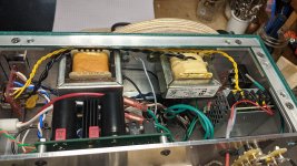
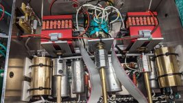
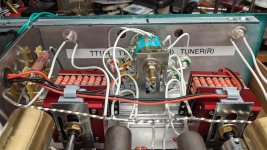
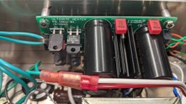
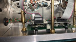
Some inside pics.
Attachments
First check where the volume pot connects to the ground bus, compared to where
the tube cathodes and power supply returns connect. Where is that?
Both channels share the same ground bus? Is the power supply wired like the schematic
in terms of how the capacitor ground returns are connected to the rectifier?
Generally, the center of the shared ground bus should connect to the chassis and to the shared power supply.
The audio circuits connect to points farther away on each side of the center, and the input and volume control
returns connect to the far ends of the ground bus.
Last edited:
I have it wired very close to the schematic I sent you. The ground "network" is grounded to the chassis at the input jacks which are insulated from the chassis.
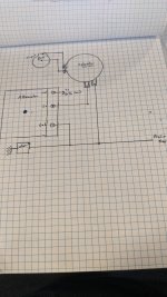
The PSU caps are at the other end of the bus. The cathode, resistor grounds as well as the attenuator grounds and the input and output grounds are daisy chained along the bus. I'll work on a sketch to post.
The PSU caps are at the other end of the bus. The cathode, resistor grounds as well as the attenuator grounds and the input and output grounds are daisy chained along the bus. I'll work on a sketch to post.
If the HUM is low @ min volume, and high @ mid volume and then low @ max volume you then have a loop pickup problem. The output Z of the attenuator is max @ mid volume position. What is the HUM LEVEL @ low, mid & max positions?
The 90Hz may be a power supply problem of mismatching of balance of the rectifiers or pcb routing. Do an FFT of the power supply voltages.
Duke
The 90Hz may be a power supply problem of mismatching of balance of the rectifiers or pcb routing. Do an FFT of the power supply voltages.
Duke
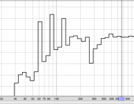
REW allows a much better frequency resolution of frequency spectrum than that the plot shown in post #3. In RTA, open the graph controls and in the pop-up box confirm that Mode is set for spectrum - also read the help files for a general understanding of the various controls. Of course that requires a low ambient noise environment when using a microphone. The 'Appearance' controls allow you to display a 'peak' plot that may allow easier indication of main frequency related continuous hum.
What meter options do you have, and have you tried to use that measurement for just the preamp output? If you can start with just the preamp by itself, with inputs shorted, then you may be able to categorise the hum when excluding certain sections (like, the hum breaker, and using a battery for heaters).
There is also a switchmode supply module in that mix?
Can a DVM register a non-zero measurement for hum output on the lowest ACV range (eg. a mVrms range) ? Always good to have a benchmark reading before making step changes.
Can the Digital scope do FFT ? If not then I recommend the soundcard and REW - although that can take some care to confirm there is no ground loop hum being inserted due to the measurement (ie. a laptop is a good PC for audio testing).
Can the Digital scope do FFT ? If not then I recommend the soundcard and REW - although that can take some care to confirm there is no ground loop hum being inserted due to the measurement (ie. a laptop is a good PC for audio testing).
- Home
- Design & Build
- Equipment & Tools
- How to Measure Hum?