Driver Stage Issue for SE Amp
- By meskunak
- Tubes / Valves
- 39 Replies
Hello all,
I hope everyone is doing well during these times.
This is my first post and a call for help, so I appreciate everyone`s input and wisdom greatly.
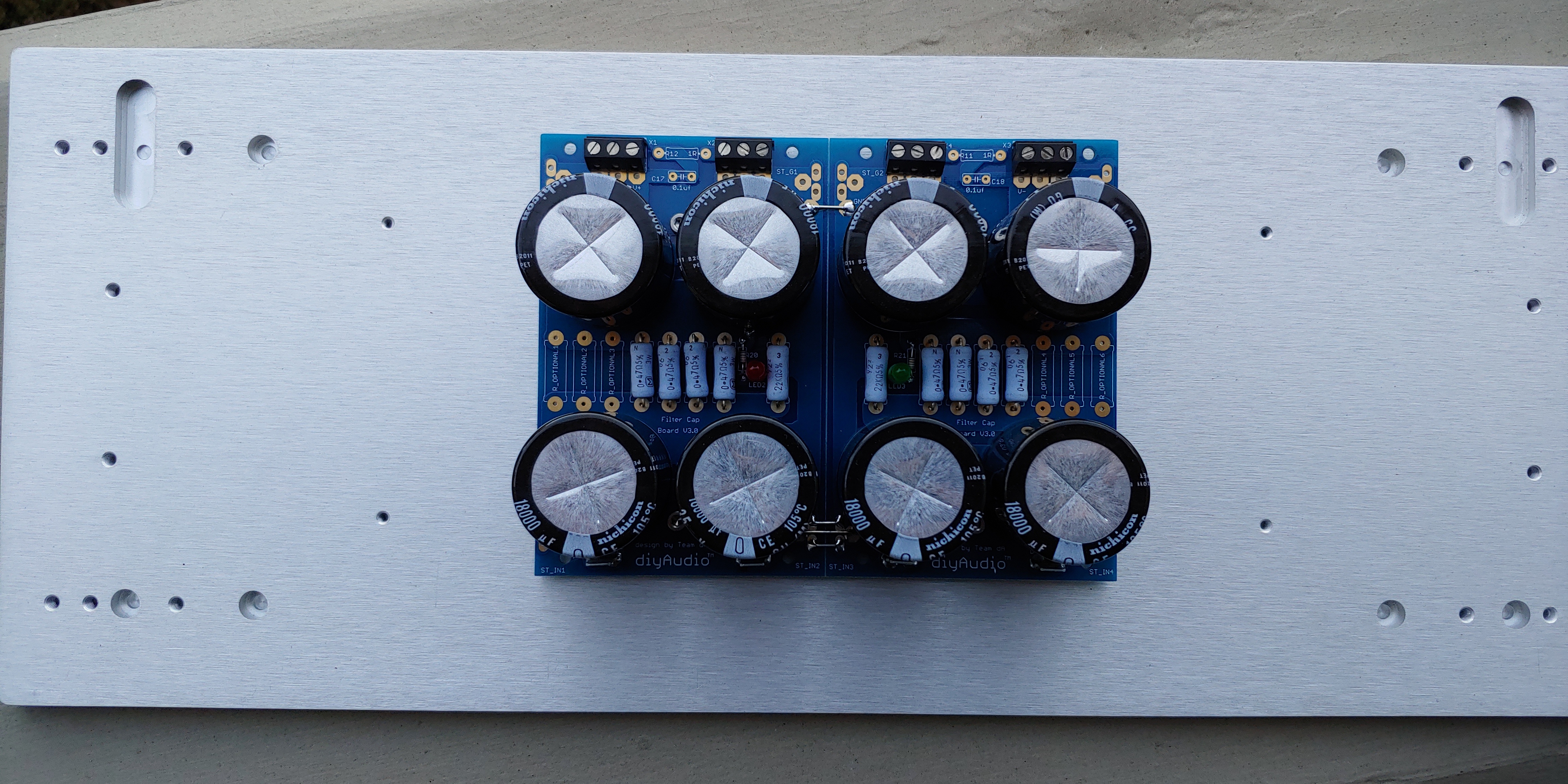
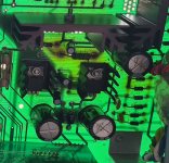
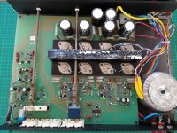
I have built my first ever tube amp, a SE design from Popovich`s book on tube amps, and build a power supply for it from scratch. Now I wasn’t 100% sure of the power supply for this amp, but the idea was to supply all voltages from separate windings, with bridge rectifiers for each circuit, as they are cheap and available. Upon the turn on, to have only heaters and negative bias on, and then via separate switch B+.
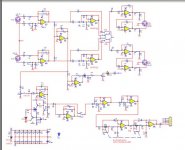
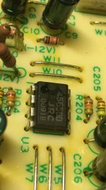
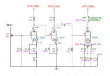
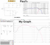
I fed 2Vpp 500Hz sinewave signal from the signal generator to the amp, after the preamplifier stage it gets to 31Vpp, looking all good, after passing through one half of 5687 it is amplified to 50Vpp, but with the top of the sinewave well flattened.
While testing voltages without any tubes in the amp, the voltages vary quite a lot, but with all tubes in voltages drop closer to intended values +-10%.
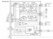
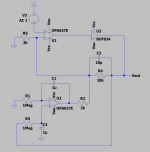
And now the part that throws me off, is the driver and output stages. The driver tube`s grid has the correct negative voltage and seems to be all fine, but the cathode of the driver tube has reversed polarity, instead of negative as in the schematic I get the same voltage positive? Even it is connected to negative voltage?? which effectively makes output tube`s grid positive 😕 Why does this happen? I have a feeling that I must`ve got something fundamentally wrong here, but after the amount of time spent which is equal to wanting to smash this thing to pieces, I can't really find the answer .
.
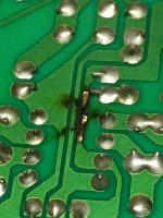
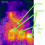
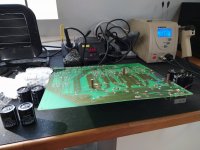
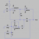
I tried to troubleshoot with the test lamp to see if there are any shorts, which there weren’t any. I double-checked all solder joints etc. and all seem sturdy, checked all the connections. I did try to change up a bias and driver`s power supply a little (version 2) where driver plate and negative bias were fed from the voltage doubler symmetrical circuit, to see if this makes any difference, but nothing. Did some other various changes to the power supply, but the result is the same,
I would really appreciate any help to get some output here.
Thanks,
Karolis
I hope everyone is doing well during these times.
This is my first post and a call for help, so I appreciate everyone`s input and wisdom greatly.
I have built my first ever tube amp, a SE design from Popovich`s book on tube amps, and build a power supply for it from scratch. Now I wasn’t 100% sure of the power supply for this amp, but the idea was to supply all voltages from separate windings, with bridge rectifiers for each circuit, as they are cheap and available. Upon the turn on, to have only heaters and negative bias on, and then via separate switch B+.
I fed 2Vpp 500Hz sinewave signal from the signal generator to the amp, after the preamplifier stage it gets to 31Vpp, looking all good, after passing through one half of 5687 it is amplified to 50Vpp, but with the top of the sinewave well flattened.
While testing voltages without any tubes in the amp, the voltages vary quite a lot, but with all tubes in voltages drop closer to intended values +-10%.
And now the part that throws me off, is the driver and output stages. The driver tube`s grid has the correct negative voltage and seems to be all fine, but the cathode of the driver tube has reversed polarity, instead of negative as in the schematic I get the same voltage positive? Even it is connected to negative voltage?? which effectively makes output tube`s grid positive 😕 Why does this happen? I have a feeling that I must`ve got something fundamentally wrong here, but after the amount of time spent which is equal to wanting to smash this thing to pieces, I can't really find the answer
. I tried to troubleshoot with the test lamp to see if there are any shorts, which there weren’t any. I double-checked all solder joints etc. and all seem sturdy, checked all the connections. I did try to change up a bias and driver`s power supply a little (version 2) where driver plate and negative bias were fed from the voltage doubler symmetrical circuit, to see if this makes any difference, but nothing. Did some other various changes to the power supply, but the result is the same,
I would really appreciate any help to get some output here.
Thanks,
Karolis
PHP:


