First of all props to the basis of my design, beeing ThatMicPre!
Really nice circuit!
For my case however, I need digital control, but I also want to avoid small QFN parts...
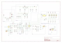
So I started CADing a modified version. I added:
-Gain control using the DG412 switching IC (according to this paper)
-Digitally controlled phantom power
-Line in with combo jack
One downside is that the full 60dB gain can not be reached, because of the high on-resitance of the DG412...
How would you solve the task of digital control?
I would really appreciate any feedback on my edits.
Are there simpler solutions to this?
Any tips and tricks are very welcome!
Really nice circuit!
For my case however, I need digital control, but I also want to avoid small QFN parts...
So I started CADing a modified version. I added:
-Gain control using the DG412 switching IC (according to this paper)
-Digitally controlled phantom power
-Line in with combo jack
One downside is that the full 60dB gain can not be reached, because of the high on-resitance of the DG412...
How would you solve the task of digital control?
I would really appreciate any feedback on my edits.
Are there simpler solutions to this?
Any tips and tricks are very welcome!
Mosfets instead of Analog switching IC
Maybe the analog switches can be replaced with n-channel mosfets connected like this?
Because of the elimination of a dual rail power supply, ground should always be below signal level, therefore the mosfet diode is not a problem.
Just a thought, maybe I am totally wrong here...
Maybe the analog switches can be replaced with n-channel mosfets connected like this?
Because of the elimination of a dual rail power supply, ground should always be below signal level, therefore the mosfet diode is not a problem.
Just a thought, maybe I am totally wrong here...
Checkout MAX4638/9 low resistance switch chips... 3.5 ohms, however 5V operation which will be problematic.
You can also parallel the switches in a DG412's for lower resistance - use 4 in parallel for the lowest value, 2 for the next, 1 and 1 for the higher resistances.
You can also parallel the switches in a DG412's for lower resistance - use 4 in parallel for the lowest value, 2 for the next, 1 and 1 for the higher resistances.
Hi helixfoo!
Thank you for your interest in my open source design!
Digital control and cmos switches are indeed possible to implement. There are some switches with Ron as low as 1ohm from Analog Devices. I have succesfully used those before.
A tip is to divide the gain resistor in two so that instead of one say 100ohm resistor on one side of the switch you put two 50ohm resistors on either side of the switch. That way the AC signal swing at the switch is nearly zero and so nonlinear capacitance etc does not matter so much.
Gain Control with MUX
Thank you for your suggestions!
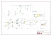
I now started a version using an analog multiplexer for gain control,
because it is cheap and allows 9 gain stages.
I am using the MAX4617 with Ron of 8ohm.
However this chip is only rated for 5V analog. Do you think this can work?
What's the maximum voltage I can expect between RG1 and RG2?
Is it a problem to use the real GND on the chip, because the signal has 18V as center?
Maybe dividing the electrolythic cap in two and placing it before and after the MUX decouples the signal?
Thank you for your help!
Thank you for your suggestions!
I now started a version using an analog multiplexer for gain control,
because it is cheap and allows 9 gain stages.
I am using the MAX4617 with Ron of 8ohm.
However this chip is only rated for 5V analog. Do you think this can work?
What's the maximum voltage I can expect between RG1 and RG2?
Is it a problem to use the real GND on the chip, because the signal has 18V as center?
Maybe dividing the electrolythic cap in two and placing it before and after the MUX decouples the signal?
Thank you for your help!
Attachments
Last edited:
This will be problematic. You will save yourself a lot of headache if you choose a mux or switch that has 30v or more supply limit.
The voltage on RG1 and RG2 will be approx the same as that on the input pins in- and in+. Which is mid supply voltage plus the input signal swing.
The voltage on RG1 and RG2 will be approx the same as that on the input pins in- and in+. Which is mid supply voltage plus the input signal swing.
- Home
- Source & Line
- Analog Line Level
- THAT1510 mic-preamp with digital control