tired tubes?

Just bought an amp and I tested all the tubes discarded the bad ones and now have a full complement of tubes that test good. I know from the previous owner that they have a good number of hours on them but dont know exactly. They are quiet no noise. How do I know if sonically they are tired? The 6550 should be replaced after 3000 hrs and the tubes date codes are 2001. Not sure I want to drop $500 only to find out I dont need them.

6n24p / 6H24∏

Does anyone have any experience with these tubes? I just bought a handful for a decent price and had some time to play around with one doing some distortion measurements before I needed to recharge batteries. The measurements came out with 2nd harmonics roughly -45 db under fundamental and 3rd another 5 db behind that. That was pretty consistent through the small amount of points I tried. One thing that struck me was that the operating points don't line up with any of the current data available online especially at higher voltages. I originally planned to use this tube as a driver for a 6a3, but I am going to move on to other options and save them for shunt cascode experiments given their decent gm. Just curious if anyone has any experience.

$360 for a hole...?

Hello everyone,

I was reading on the forum until late last night about how I can punch a rectangular hole in a piece of sheet metal. To be specific, I'm talking about the sheet metal used in the Hifi2000/DIYAudioShop Pesante chassis. (My ultimate questions are highlighted below.)

I've had the electrical portion of my design project done since last year, and I set out on the task to finish the job, but Hifi2000 says they can't mill/drill/punch/etc. the steel they use in the Pesante rear, side, top, and bottom panels. I have a Schurter AC supply socket that I want to use, but it is bigger than the simple IEC panel cut-outs they offer. I also want to be able to hide the power switch that I selected on the bottom panel of the amp on the front right side.

From what I read here, the "best" solution is to find a Greenlee knockout punch. The knock-out that is closest in size to my power switch is $360. That is a very expensive hole. I also tried to find the q-max punch mentioned, but I was unsuccessful in finding one of an appropriate size. Does anyone have a link to their website? Searching for "qmax" in A LOT of results. I would need still a different size punch for the power cable connector.

Is there a type of professional shop that I can look for that might have these types of tools and could do this for me? I will also need drilling of round holes for I/O in the back panel and holes for mounting the feet in the bottom panel. What kind of shop would have a CNC that can mill 1 mm steel?

Jeff

wiring for chassis XLR

I've built a Pass F5T and I'd like to wire up the two XLR female connectors incase I decide to use them in the future.

From what I've read about XLR, there's a bit of voodoo that takes place somewhere along the line (the difference of two wires get's thrown out) perhaps at the connectors?

I want to be sure I get the wiring correct for them, and didn't find much about wiring up the actual connectors vs new wires on youtube and the web.

I got a pair of Cardas CM F XLR
CM F XLR (Female XLR)

From the internal boards, I have a Left +, Left - and Right +, Right -.

thanks

Attachments

  • cm_f_xlr_connector.png
    cm_f_xlr_connector.png
    688.7 KB · Views: 347
  • cm_f_xlr_main_transparent.png
    cm_f_xlr_main_transparent.png
    660 KB · Views: 347

class d gate dri tranformer

gate dri tranformer class d , tl494 mod for class d
it simple circuit i test +110v load 4 ohm fre-class d 75k-130k

????????????????half bridge to class d amplifly by foodland - YouTube

Attachments

  • 494 mod1.png
    494 mod1.png
    40.3 KB · Views: 119
  • 494 mod1a.png
    494 mod1a.png
    55.1 KB · Views: 131
  • 263445653_270574828421583_1063610926827917626_n.jpg
    263445653_270574828421583_1063610926827917626_n.jpg
    148.3 KB · Views: 125
  • 263506095_307887084470347_4035524371642613434_n.jpg
    263506095_307887084470347_4035524371642613434_n.jpg
    152.8 KB · Views: 101
  • 263389129_639439240826963_4284918566500472676_n.jpg
    263389129_639439240826963_4284918566500472676_n.jpg
    86.8 KB · Views: 99
  • 263599804_292743842772267_4123929137257611727_n.jpg
    263599804_292743842772267_4123929137257611727_n.jpg
    99.2 KB · Views: 82
  • 262940765_1424222571326638_1704579480492882429_n.jpg
    262940765_1424222571326638_1704579480492882429_n.jpg
    111.4 KB · Views: 98

For Sale: Bel Canto EVO 200.2 Amp and SEP 2 Tube Preamp

For Sale: Bel Canto EVO 200.2 amp with Tripath based TA105A amp unit.

Amp power supply caps have been replaced with ew and ready for another 25 years. Widely lauded as the one Solid State amp that sounds most like a tube amp due to the Tripath Class T design.

Asking $875 for EVO 200.2 Amp

Also have the matching SEP2 Tube preamp. Tube compliment is a pair of newer 6922 Tubes. Pre has aftermarket remote.

Asking $875 for SEP2 preamp

May be able to make a package deal for both. Not a scratch on either amp or preamp and both work perfectly.. .

Ships from West sub of Chicago or pickup...

Attachments

  • 01313_c2QGIhKsdnrz_0CI0lM_1200x900.jpg
    01313_c2QGIhKsdnrz_0CI0lM_1200x900.jpg
    53.1 KB · Views: 267
  • 00t0t_cY7rse3ALE9z_0CI0lM_1200x900.jpg
    00t0t_cY7rse3ALE9z_0CI0lM_1200x900.jpg
    67.2 KB · Views: 257
  • 00g0g_a1d7hQsvm12z_0CI0lM_1200x900.jpg
    00g0g_a1d7hQsvm12z_0CI0lM_1200x900.jpg
    44.5 KB · Views: 259

Dipole Midbass Linkwitz LXSub4

Hello,

I'm looking to build something similar to the Linkwitz LXSub4 Dipole for use 50-400Hz (see image). I have 4x 15" drivers (Faital 15PR400) and each pairing would be driven by a MiniDSP 450W amplifier with DSP EQ/Crossover.

The plans are available to purchase, which is great, but the drawing is for 10" drivers, and I'm not wholly invested in the idea. I am looking for a quick proto to assess, before moving on to something more traditional if it doesnt work out.

If anyone can please advise: are precise dimensions required for this to work properly, and by extension, therefore also required for a 'scaled up' version?.

I did try to extrapolate from the internet drawing, and I am almost certain this drawing is not 100% accurate - no surprise as they require you to 'buy a license and then the plans'.

Hopefully someone has been here before with this design, or something similar, and can advise.

Thank you

Attachments

  • 0.JPG
    0.JPG
    49.9 KB · Views: 377
  • 2.JPG
    2.JPG
    14.7 KB · Views: 342

Hafler DH-110 problem

A couple years ago, a guy who worked for me gave me a Hafler DH-220 power amp and a DH-110 pre-amp. I’m just getting around to trying them out. Haven’t tried the power amp yet, but the pre-amp seems to have a problem. The right output is about half as loud as the left, and sounds subdued, or muted. I tried swapping the inputs from the source and the right channel is still the problem. I tried swapping the outputs to the power amp and the problem moves to the left speaker. I tried this with the source in both AUX and Tuner modes. Any ideas?

I don't know much about electronics, I'd just like this thing to work.

Appreciate any help I can get.

Thanks,

grym

Walsh Infinity tweeter rebuild

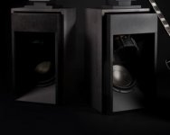
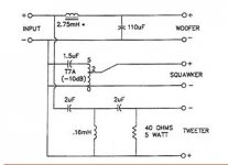
After all the excellent info and help I've received from this and other online forums, I wanted to give back at least a little re my recent Infinity Walsh tweeter rebuild / diaphragm replacement. I was hoping to improve the efficiency and power handling if possible. It came out great, a little louder than my other all-original one with slightly better dynamics on loud transients. I'm running a separate 50W/ch HF amp with 3.5kHz 12dB/octave passive line-level crossovers (Harrison Labs) + 10uF Solen coupling caps for a total of 18dB/oct. These tweeters never cease to amaze me - all kinds of music, dialogue, falling rain on pavement, wind in tree leaves, cymbals/hi-hats/bells etc, shell casings 🙂 - you name it.


1002691d1638652982t-walsh-infinity-tweeter-rebuild-1-walsh-infinity-driver-base-jpg


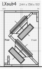
The base is machined Delrin, and I also had 'top hats' made that I didn't use (blocked out too much top radiation). I have diagrams for both if anyone needs them.

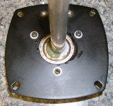
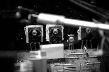
I tried unwinding & resoldering the voice coil wire after reading about it online, but it was too damaged to salvage. The voice coil was partially burnt black; I was amazed, as these tweeters were bought NIB from Infinity in the late '80s and sat untouched in their boxes for 30+ years, then used less than an hour before one failed on a loud snap-transient, blowing a 1A inline fuse. Now that it's apart I'm sure it was repaired and re-sold as "new", as the diaphragm center-hole cutting and cone gluing were awful (the other one looks perfect). I think the transient may have caused this already burnt coil to DC-short to the gap OD. The center post had a huge off-center blob of epoxy at its base which rubbed the new diaphragm. With careful taping and a little luck, I managed to Dremel this away without cutting into metal or filling the gap with crap.

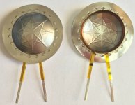
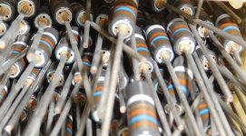
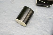
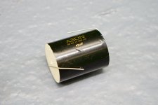
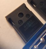
After a trip to my machinist for advice and punching holes thru several ebay titanium diaphragms, I ended up using the one below ('scarlettchen' at ebay). The diamond-shaped surround stampings add a lot of stiffness & support:


1002692d1638652982t-walsh-infinity-tweeter-rebuild-2-titanium-diaphragm-ebay-scarlettchen-jpg


The titanium in this diaphragm's dome is thick enough to punch, but the punch should be fresh and tight (my machinist's wasn't, but it still made a fairly clean .75" hole). The coil got torqued a little in the process though, so I ordered another & cut the hole by hand using a disposable scalpel & 4" Fiskars scissors (came out OK, but a little close on one side which made epoxying scary later). If I was rebuilding a conventional dome tweeter I would've preferred a thinner diaphragm, but supporting a big aluminum cone is a heavy lift for a tweeter, and with one possibly alignment-related blowout already I'd rather be safe than sorry this time. This unit also has twice the OEM winding length, which should significantly improve thermal power handling.

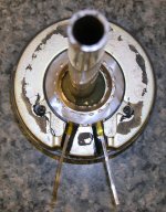
This diaphragm's flat, angled leads required ground channels in the plastic washer & top of the base (magnet structure) for the leads to fit into, which were painted for insulation / easy sliding / rustproofing.

The OEM diaphragm uses a precision plastic washer for clamping & centering which fits into an equally precise circular recess in the base, and worked just fine. After making up a 1"-diameter paper shim with 25lb smooth-stock paper and fitting it to the pole piece, I put the washer in the recess, applied 4 small drops of contact cement to the top of it, then immediately slid the voice coil over the shim & the diaphragm down on the washer / glue drops (no drying time before contact) & screwed down the top flange plate medium-tight. This is not the way contact cement is normally used, but the diaphragm centered perfectly on the thinly-spread wet glue w/no excess, and came out great. The contact-cement joint only has to hold the diaphragm & washer together when they're removed to pull the shim out, which wasn't easy... I ended up sliding pieces of Scotch tape down each side of the gap, & luckily one of them stuck to the shim paper enough to pull it out.

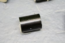
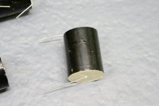
After cutting, grinding, and painting:


1002693d1638652982t-walsh-infinity-tweeter-rebuild-3-ready-top-plate-jpg


Top plate on:


1002694d1638652982t-walsh-infinity-tweeter-rebuild-4-ready-cone-jpg


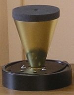
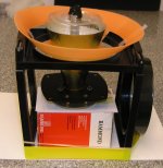
I then set up the gluing jig (below).


1002695d1638652982t-walsh-infinity-tweeter-rebuild-5-cone-jig-jpg


It took a ton of fiddling with cardboard height shims on the center box, the clear cup lid centering aid, the orange 'funnel', etc. to get everything aligned - I also had to figure out an 'escape plan' to get the completed tweeter out of the jig after the cone was glued in place - and then many dry runs inserting & aligning the cone quickly and correctly, but finally I managed to to epoxy it to the diaphragm. I looked at a number of epoxies - many were opaque and/or set up too quickly for my taste - finally settling on Devcon 14251 clear epoxy (2-part syringe, 8-10 min. set time, 12 hr cure). I painted the epoxy on the surround/VC OD area & applied it to the cone edge with my fingertip, lowered the cone thru the jig and onto the diaphragm, then added extra epoxy to the bottom cone ID with the brush. I'd recommend absolutely NO caffeine, and a good night's sleep beforehand. 🙂

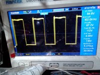
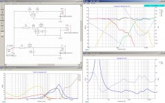
24 hrs later, I cut away two large sections of the orange funnel thing, slid it to the side & removed it, then lifted the tweeter out thru the jig center opening from the bottom. I tested it with .25W / 10Hz (no VC rubbing heard or felt), then 1W 2khz - 20kHz sine/square sweeps; as expected some weak resonances were present, but nothing major.

I got more Polyfil on Amazon, but my original stuff was pre-cut to size & still good so I re-used it. It had packed down a bit, so I pulled it up & apart so it nearly filled the entire cone loosely.

Next was the foam. I wanted precisely-cut foam circles and wasn't impressed with Infinity's single undersized one, so I went with something that to my ears worked better - two different foams, each for its own task. These were waterjet-cut by Foam N' More (www.foamforyou.com) for a very reasonable price - Michelle was extremely helpful. After trying several things, here's what I ended up using:

Foam 1 (in top ID of cone): Regicell 30 ppi polyethylene reticulated, black, 0.5" thick, .375" ID / ctr hole, 3.25" OD
This foam supports & centers the cone, and damps mechanical resonances in the moving system. It compresses readily but is stiffer than Foam 2 below, & is @ 90% acoustically transparent. Foam N' More stocks it, in 24 x 36" sheets (1 sheet minimum). I trimmed the bottom edge OD slightly so it would slide into the cone without binding. I was very careful not to let it snag the cone edge or stress the cone in any way.

Foam 2 (fits flush on top of Foam 1): 80 ppi polyurethane reticulated, black, 0.5" thick, .375" ID, 3.35" OD
This foam damps the reflected wave into the cone interior, minimizing acoustic resonances. It is softer and denser than Foam 1, and is @ 20-30% acoustically transparent. This foam appears identical to what Infinity used, and was not easy to find - Merryweather Foam makes it (p/n 80PPI.5"XHALF I think, www.merryweather.com) and Nick there was kind enough to send me free samples as they have huge minimum orders. I then sent the sample foam to Foam N' More for cutting, which they were happy to do. Nearly any open-cell 80-100 ppi polyurethane foam should work fine for Foam 2 in a 2-foam setup, and for a single-foam Infinity setup if it's stiff enough (like the Merryweather foam) AND sized correctly to not stress the cone glue seam (3.20" OD, trim bottom edge if needed).

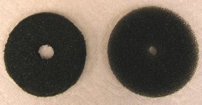
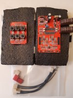
Here's the OEM foam on the left (@ 3.125" OD, degraded) and the new 30 ppi Regicell foam on the right (3.40" OD, way too big - it was my 1st attempt). The new foam's center hole looks like crap in this pic, but it's perfectly round & centered. The 80 ppi polyurethane foam mentioned above is shown in my 1st pic, it looks nearly identical to the OEM foam below.


1002696d1638652982t-walsh-infinity-tweeter-rebuild-6-oem-3-125-od-30-ppi-regicell-3-40-od-foam-jpg


I used the tweeters for a while with no foam at all (just Polyfil), and also with only Foam 2 placed just above the cone edge. With Polyfil-only they were noticeably louder (especially from the top - mine reflect off a 45° knee wall 14" above), with more hi-mids & an edgy / sibilant tone. Adding Foam 2 dropped the reflected level & mids a lot, but the edginess remained until both foams were used w/Foam 1 contacting the cone, when it instantly vanished.

Well, that's about it for the rebuild. I also made up a tweeter protector for these so (hopefully) this ordeal will never be repeated, and at some point I'll post about that. I might also have the rest of the Merryweather sample foam cut for sale on ebay at some point. The pics aren't displaying as I hoped they would, any suggestions appreciated.

Attachments

  • 1 Walsh Infinity driver & base.jpg
    1 Walsh Infinity driver & base.jpg
    14.1 KB · Views: 1,276
  • 2 Titanium Diaphragm (eBay, scarlettchen).jpg
    2 Titanium Diaphragm (eBay, scarlettchen).jpg
    92.9 KB · Views: 1,167
  • 3 Ready for Top Plate (small).jpg
    3 Ready for Top Plate (small).jpg
    164.3 KB · Views: 1,027
  • 4 Ready for Cone (small).jpg
    4 Ready for Cone (small).jpg
    252.1 KB · Views: 1,055
  • 5 Cone Jig (small).jpg
    5 Cone Jig (small).jpg
    94.9 KB · Views: 1,028
  • 6 OEM 3.125 OD & 30 ppi Regicell 3.40 OD foam (small).jpg
    6 OEM 3.125 OD & 30 ppi Regicell 3.40 OD foam (small).jpg
    86.7 KB · Views: 925
  • Like
Reactions: mcspack and deanznz

Sansui AU-101 - weird boom / high-pitched sound / Feedback

Dear All,

I have just received my Sansui AU-101 today in really good cosmetic condition (well chuffed), and fired it up with Wharfedale Denton 80th Anniversary addition speakers (6 ohm suitable for 20w - 100w amps per manufacturers recommendation).

However, with loudness turned on, if I turn the bass dial beyond 0 or turn the volume up beyond level 4, it creates that high-pitched sound as if when your mic is too closed to your speakers, like a loud boom in the room. Could someone help me out what could be the case, is it the speakers being too heavy or are we talking something wrong with the amp?

With loudness on, it produces sweet warm sound till up to volume level 4, and with loudness off, I can turn it up more. With loudness on, if I turn the bass all the way to + same boom / high-pitched noise starts again.

Many thanks in advance for your help.

Stepped Attenuator for HF gain setting on crossover

I have a two way crossover and the horn driver gets ahead of the two 12" woofers real quick. I can use a Mini DSP HD I suppose and tame this thing but what I really want is a good way to attenuate the HF horn drivers to match the woofer output on a crossover. Right now I am using a pair of L-Pads from Parts Express but I want something more precise than those.


I read about stepped attenuators and Goldpoint comes up often so I get a set in. These things are tiny and I can't find any wattage capacities on Goldpoints units nor has Goldpoint answered the phone so far. Honestly I have not tried all that much to reach them so not casting shade here. I figured I would ask here while waiting to hear from them and see if these are even what I should be using.


I am told that you can measure output from an L-Pad to derive resistor values for a two resistor L-Pad.


So anyone have any input on the Goldpoint and attenuating 150 watt driver down to match two woofers? I am afraid I bought something way to insufficient for the wattage I will need to take care of.


Any ideas other than trial and error and a suitcase full of resistors to figure out values? I was hoping to use the Goldpoint as both attenuators for my system and a source of accurate measurement for resistance values I could measure off them then make fixed L-Pads for further ones.

Kicad for MacOS High Sierra

Kicad official support for older Macbooks with MacOS older than High Sierra is no longer available.
As long my mid 2010 Macbook will survive (me too as well 😀 ), I'll post here my latest Kicad compilations for Kicad.
I always compile latest tag from Kicad gitlab.
Hence Kicad 5.1.12 is a bit ahead of official release.

Kicad for MacOS High Sierra - Software - KiCad.info Forums

Enjoy !

Regards,
tibi

Wifi vs Ethernet

hi guys,

hays anyone experienced that their wifi connection sounds better than wired ethernet? I certainly have. I stumbled upon this by accident where by i was having connection issues with my wifi so i hooked up the streamer via ethernet. The connection issue was solved but the sound quality was poor via ethernet when compared to wifi.

I replaced the router which fixed my wifi connection. I switched back and forth between wifi and ethernet and the wifi certainly sounds better, cleaner.

has Anyone has experienced this? Please share what you did to fix the issue?

Thanks

Selector I2S : 4x inputs => 1x Output

Hello all,
Sorry for my english...

My project is create a DAC with differents I2S sources: a receiver (SPDIF + toslink + Amadero) + bluetooth + raspberry + 1 free source available.
Each source has it own I2S output.

It's a bit complicated but I prefer a scalable solution with separate elements that I could upgrade separately: a source part (spdif + usb + bluetooth + raspberry + ...) => i2s => reclock / isolator => DAC , rather than a full DAC on a single card, knowing that the problem always arises to integrate a raspberry on a DAC integrated in I2S ...

I would therefore like to implement an i2s selector (MCLK + BCLK + LRCLK + DATA) allowing to choose 1X4 outputs among 4x4 inputs to attack the DAC from 4 different sources.
I am wondering how to set up this system, because I am not very knowledgeable in electronics.
I have the possibility to set up for example 4 x HC573 (https://assets.nexperia.com/documents/data-sheet/74HC_HCT573.pdf) or to use 16 x Takamisawa NY-24W-K-IE (https://www.fujitsu.com/downloads/MICRO/fcai/relays/ny.pdf).
If possible, I would like to avoid cascade, for example avoiding putting 3 x 74HC157.
Do you have any ideas on what implementation i could do to get the best signal possible? Are there more efficient chipsets to pass I2S signals with the high frequencies found on this bus and that without noise?

I saw that : Input Selector 4x I2S Input to 1x I2S Output - Audiophonics

But i would want to make my own mother card with spdif-toslink-usb or blutooth as daughters cards (and the logic to select input) to avoid cables and noises. So if i have to implement the selector on my mother card, i can make the best selector 🙂.

Thank you in advance and best regards
Christophe

Underseat VS trunk mounted Subwoofer

hi

Recently an alternator failure overcharging blown my dynaquest underseat subwoofer render it out of service ... now i am looking for a replacement ... i have 2 choice now ... a replacement unit for the underseat unit or a rear trunk mount conventional subwoofer unit? if i am going for the rear trunk unit i will remove the 2 units of 6x9's to let the bass enter the cabin easily ... and if is trunk mounted unit i will go for double 10's ... but a question here if i am going to remove the 6x9's (shown in picture and FYI those speakers were not working/BLOWN and no point keeping it on the rear tray) to let the bass in what else alternative can be done for the rear channel speakers? my previous car projects doesnt deliver promising bass with any speaker on the rear tray blocking the bass waves into the cabin. The rear trunk of this old car is isnt very big

or another option here is after i removed the 6x9's ... i will PORT the box into the cabin which is the listening area while another port fires into the trunk ... will that work too?

if i am going for the underseat replacement same unit and model it will be just a plug and play job but the bass level doesnt meet my satisfaction.

Selected candidate for the 2 10's subwoofer (170mm magnet) will be as shown in picture ... and can i just use prefab box or i need to calculate and build own box? (too lazy to build my own box and currently working😀) i dont mind sacrificing trunk space at the moment because i dont carry many stuffs behind the rear trunk. Box will be slot ported box regardless of prefab or custom home made box

current setup = 6inch component door mounted speaker tweeter dashboard mounted and underseat subwoofer + Android multimedia player

any opinions ? thanks

Attachments

  • TB2_U5obpXXXXbDXpXXXXXXXXXX_!!102264685.jpg
    TB2_U5obpXXXXbDXpXXXXXXXXXX_!!102264685.jpg
    335.8 KB · Views: 189
  • 242801919_3115388778674475_4038093826315310798_n.jpg
    242801919_3115388778674475_4038093826315310798_n.jpg
    826.9 KB · Views: 186
  • 161431322_2968655626681125_3794874508300279172_n.jpg
    161431322_2968655626681125_3794874508300279172_n.jpg
    213.4 KB · Views: 197
  • 160272578_2968673873345967_247421728976488554_n.jpg
    160272578_2968673873345967_247421728976488554_n.jpg
    138.5 KB · Views: 186
  • 160008869_2968747386671949_4650189691683011427_n.jpg
    160008869_2968747386671949_4650189691683011427_n.jpg
    114.5 KB · Views: 189

NAD 3020i output voltage issues

been a while since ive asked for any help and i try not to these day as i want to be able to work it out for myself-but!
i have one here i just cant work out, both speaker outputs are -26v


when i got the amp both output transistors were blown on the right channel and fuses along with them as you woudl expect, so they were replaced.
I have since checked and tested all other transistors in the output Q401 through to Q418, both channels and all are ok.


the power sections on both rails have the correct outputs.


i have -26v on all 4 output transistor bases and emitters
i also have -26v on the feedback resistors R429 and R430, in fact pretty much -26v all over the place so i dont have a good starting place.


ive been trying to work out what what genericaly could affect both channels the same 😕


any ideas?

E188CC power supply advices needed

Hello tubes folk,

I am looking for my first tube work, a cheap but good enough stuff for the circa 70V/circa 12 mA plate of an Philips E188CC. This low microphonic tube will be used for the cool nice Thosten Losch I/V stage, for the TDA1541A.

I want the easiest and cheapest way: no expensive power transformer with center tape. No rectifier tubes, no Tango choke for the plate. Foun a 240/0.1A 6,3V/2A power traffo and also one with 235V/0.05 A but R Core with no screen.

As the tube is a non used pretty cool NOS from 1974, 10 000 h rated, my goal is to include some life span protection, i.e. soft start and CCS. Reg for the filament.

A friend advices me the Moglia gyrator pcb for instance for the plate but it is a litle complicate to import things in continental Europe today and the christmass period is not enhancing that, uh.

I also read about CCS coupled with caps multplier which is a litlle less efficient on the ripple than a gyrator but much better for the noise. It has also a lower output impedance than a gyrator if I understood what I read from Elvee, Prasi, Mark Johnson and numerous skilled members. But my understanding is a tube is sounding better if powered by a higher impedance so the gyrator being more the logical choice ? PSRR only and get rid of the noise floor needed with 16 bits DAC (around 95 to 100 dB ???) ?

Seems also a IHT tube does't need sota low noise for the filament but a soft start for a solid state rectifier circuit is a goodn dea for the tube life spam though. Danger being the filament being hot enough when the plate is powered.,..counterproductive for the tube health. This a 6,3 V/375 mA filament.
Better to use it 6,20 V for example if the life span comes before the sound quality target?

How would you proceed, please ? Two power switch one first for the filament with a soft start to avoid the inrush voltage/curent and a second power switch for the plate ?

What would be your choice for the non choked plate, a CCS gyrator, a reg & cap multiplier with tamed peak voltage at start on? Something else ?
Is anyone aware about gerbers or cheap pcbs for that ?

The game being to stay cheap but good enough. Could you please illustrate Loesch shematic about its power supply please. I will use just one tube only, one half for each Channel, no buffer. So not wo tubes as the pdf. But would like beginn with his cheap power stage. Found already a Hamond 159P for the choke loaded voltage rectification
Many thanks for your help.

Attachments

Has anyone tried/tested Peerless by Tymphany FSL drivers?

Hi,

Wondering if anyone here has seen some good designs or measurements/reviews of the FSL drivers? Paper cones, high sensitivity, affordable .. but how do they sound 🙂

Example drivers I am eyeballing, but haven't been able to find much on google / audio forums in terms of any 2-3way designs with them?

https://www.parts-express.com/peerl...-5-1-4-midrange-woofer-driver-8-ohm--264-1400

https://www.parts-express.com/peerl...professional-10-woofer-driver-8-ohm--264-1408

Looking to possibly build something out of these to have loads of dynamic range, but with good/great(if possible) sound and not just sheer volume.

Would probably have to use a compression horn to match the midrange, or any suggestions on a good matching dome tweeter?

Cheers!

MM Phono Pre with balanced input

Hello,

As a learning project to push myself into starting to design my own stuff rather I have been trying to come up with (yet another) phono stage.

I wanted something with a balanced input b/c I think the superior CMMR is worth it in my particular case. I do have quite a bit of EMI where I'm listening to records. So my design goals:
- Optimized for MM. (For MC carts, a head-amp can be added later)
- Balanced input to cancel out CM interference
- Keep capacitors out of the signal path as much as possible
- passive RIAA
- Optional sub-sonic/rumble HPF

So using what I've learned so far about op-amps and looking at what many others did, I've put something tohether in LTSpice.

I'm using an offset compensation through another op-amp in order to get rid of the DC offset introduced in the initial two stages.

The rumble filter is a 3rd order S-K Q=.707 filter with a 20Hz cutoff. The idea is to have switch that selects the output jacks to either connect to U3 directly (out1) or to alternatively to the HPF output (out2)

Resistors in the RIAA filter should be .1% types and the caps there should be 3% types.

I think I'm pretty ignorant about all the things I don't know yet, so if someone can spare a few minutes to look at this thing and can share some feedback on what to do differently that would be awesome...

Some points I'm wondering about in particular:
- Better choices for op-amps?
- Is it worth considering a discrete approach for the first stage instead of op-amp
- is a a good idea to place the HPF as the last piece of the chain? Would there be anything advantegeous about putting it between the RIAA and the second gain stage?
- is the offset compensation a worthwhile approach or should a DC blocking cap in the output be considered. It might just be a matter of taste, but I'd love to read opinions on this...
- Is there a better way to wire up the input to have best flexibility with balanced and single-ended sources? Also modifications to the input loading resistance and capacitance (R1/R2, C1) are interesting to me. How can that be put into practice? Some RCA jacks in parallel where one could fit caps and resistors seems to be one way to go about that but the fact that the resistive load is split across R1/R2 makes this more complicated. Is there a way to have a single load resistor and still have a balanced input?

Here's the schematic and a bode plot w/ and w/o HPF
Screenshot 2021-11-25 at 11.00.13.png

Cheers,
Lars

Leak 2000 Tuner/amp

I bought one of these fifteen years ago quite cheaply on eBay to replace a Philips 790, I'd bought new in 1972 which went U/S.
At the same time I'd bought some Goodmans Havant speakers and a Philips 308 turntable.

A couple of years later I bought new a Sharp cassette deck.


The turntable and cassette I fitted new belts about fifteen years ago, but they still work fine.

I use this system mostly to play mp3s via a couple of Rock-Ola 507 wall boxes and 3rd gen iPods. (It's all about "nostalgia" for me as I have also two vinyl jukeboxes).
Unfortunately, the Leak started "motorboating" a week or so ago so has gone in for repair.

But in the meantime, I spotted a rather sad looking Leak 2000 on e-Bay for not a lot of money. They can go for £150, but I got it for £56. The vendor assured me that it was working condition. I was also impressed how well he packed it up to send it.


As promised, it's in perfect working condition, although the tuning cord is a bit noisy in one place but doesn't stick, no mains hum at all. But the cabinet was "dog rough."
As I've a service manual, I'd previously got via a pdf from another enthusiast, I knew the top and sides came off quite easily. As they have wood veneer I guess they were added to the chassis at the end of the assembly.


The top had a lot of scratches and it was obvious the set had been stored on one end for a long time in a dusty area and dragged about several times.


But with a couple of grades of sandpaper and some Golden Oil polish and conditioner, it came back in a very presentable condition.


This was the worst side.


Anyway, it is working perfectly.
( I made this video before cleaning up the cabinet).


1970s Leak 2000 Tuner amp - YouTube


I'll still get the other repaired and this one can go in my "office" and the Rotel I bought cheaply on eBay early this year can become a spare.
This is playing through over-size speakers I put in this non=working sixties Rock-Ola jukebox wall box.


https://www.youtube.com/watch?v=F7dpvYw3fAE


I've since bought some boolcase speakers for it.


Rotel RA-980BX equivalent transistors

Hi All,


I have a Rotel RA-980BX amp with a blown channel. I have sourced most of the transistors, but am struggling to find the other 4.


Part numbers as follow:
2SC3478
2SC4381
2SA1376
2SA1667


What would be suggested equivalents / suitable replacements?


Also, some advice, I suspect the bias pot to be bad. Based on the circuit, would you think that the bad bias pot would cause the drivers and outputs to blow? Any suggestion on modification to prevent this re-occurring?


Thanks


Regards,
Werner

Attachments

Belles amplifier left bank of transistors went out

Hello
I have a Belles amp, Reference 150A V2 that quit working in the left channel. I opened the top and there is a light smoke film on the transistors. I called Dave Belles and he said to send it to a gentleman in New York for repair. I live in Colorado so I don't want to if I don't have to. So I have been asking for a good technician that could do it here in Colorado. I haven't found one yet. I am not afraid to try it myself, if I had some guidance. In high school (50yrs ago ) it took a couple of years of TV and radio repair so I can solder a little bit. If someone could probably tell me what I need to know that would maybe get me started. But not ever doing it before I can realize maybe I shouldn't. But I was thinking a couple of things I need to know. One, how do I go about getting the correct transistors. I have the numbers but I cannot find an exact number replacement. And then do I need to match them for compatibility, not npn and pnp, but individual measurement matching, if so I don't know how to do that. And then biasing them I don't know how to do that either. I am kind of helpless maybe. If anyone could provide some guidance I would appreciate it. The last I heard Mr Belles doesn't give out schematics on request. Thank you

How to test JFETs, or any active device

I am doing some time-passing activity but am a little ambiguous about my procedure.
Here I am comparing BF862 and CPH3910, and I have set them up in exact same circuits, with same value components. But this means one device idles at a slight different Id and they also have different gains... Should I adjust values for same Id? Should I adjust values for same gain? If adjusting for same gain, do I add source degeneration, or alter the load on the drain?
I am thinking I can adjust the source resistor for nearly same Id. Then I can AC-couple an amount of source resistance and adjust until the gain is similar for all devices under test.
Or are my values close enough and a few tens of mA wont make a big enough difference anyways?

My intent is to compare and measure gain, distortions, noise, Cin... what else should I add?

For noise tests I intend to simply add series resistance on the input until noise floor rises by 3dB. This is accurate enough? I will be using a 10x and 100x LNA between JFET and analyzer.

Here are some pictures of the circuit and some measurements. I dont know if I ever actually get something sensible out of this.
Oh, I misspelled CPH3910 in many screenshots...

Attachments

  • testcircuit.png
    testcircuit.png
    130 KB · Views: 156
  • BF_CPH_comparingdata.png
    BF_CPH_comparingdata.png
    247.2 KB · Views: 146
  • BF_CPH_1Vrms_thd.png
    BF_CPH_1Vrms_thd.png
    428.9 KB · Views: 129
  • BF_CPH_2Vrms_thd.png
    BF_CPH_2Vrms_thd.png
    409.2 KB · Views: 126
  • BF_CPH_degen_1Vrms_thd.png
    BF_CPH_degen_1Vrms_thd.png
    430.4 KB · Views: 128
  • bf862_commonsource.png
    bf862_commonsource.png
    55.9 KB · Views: 67
  • bf862_commonsource_RsBypassed.png
    bf862_commonsource_RsBypassed.png
    48.6 KB · Views: 76
  • CHP3910_commonsource.png
    CHP3910_commonsource.png
    51.7 KB · Views: 65
  • CHP3910_commonsource_RsBypassed.png
    CHP3910_commonsource_RsBypassed.png
    48.7 KB · Views: 74

Mixing Analog Signals Amongst Several Devices

Hey everyone, first time posting here. I'm currently working on a project wherein 7 users wearing headsets are able to talk amongst each other in a party-line manner. I've made and tested a custom circuit that supports this, but I'm having much trouble getting one of the required features of the circuit to work.

These singular boards must be able to be connected, or mixed, into other boards. In other words, I need the ability to expand my 7 channel party-line circuit to accommodate other exact boards. This will allow the entire system to have 7, 14, 21, etc. channels.

I thought I could adopt the same topology used to mix the output of the microphone preamps on each board, but it doesn't seem to be the case. The different modules, when connected, seem to fight each other. A lot of noise and clipping is present, and it is generally an unpleasant sound.

I've attached an image below to illustrate what I'm attempting to do. It's just a simple representation of what I'm currently doing. The only difference is that in my actual board, I'm using a single supply and the non-inverting input is connected to 1/2VCC. I also moved to using a ADC->DSP->DAC topology, which is shown in the images. Is virtual earth mixing the commonly accepted way of mixing/summing analog signals? Could there be an issue with multiple mix amps fighting each other? Potential grounding issues? I'm at a loss here and would appreciate any help I could get.

Attachments

  • TINA.png
    TINA.png
    94.1 KB · Views: 87

those of you who are using a laptop for streaming music music

Is it always difficult to find detailed specs for a laptop internal DAC?

I am not complaining about SQ, its quite good even considering I'm currently not even going out a USB to an outboard DAC. It blows away the same setup with the previous laptop I switched out, night and day difference. It has me thinking its packing something decent inside while utilizing the 3.5 headphone output.

Choice option 1 usually goes - USB to an outboard DAC to pre (or power amp if your DAC has a built in preamp).

Assistance with waveform description from piezo 'field recording'

Hi guys, first post, I've just started touching electronics for the first time since high school in the 90s. I'm interested in digging deeper into the rabbit hole.

I know this is tangential to most things here, but i built this piezo preamp Piezo contact microphone hi-Z amplifier – low noise version – Richard Mudhar
I'm running a scarlet 2i2 powered from a OnePlus 6 phone using USB Audio Recorder Pro android driver over a new anker usbc to usbc cable, with the idea of having a portable rig to get DIY contact field recordings. I'm well aware you might be wincing in pain by now.

My initial tests have an unacceptable amount of popping noise which I'm assuming is from high levels of static when i am trying to record very low signals at high gain. I made a grounding mat from some mesh I intend to attach to steel structures for discharge.

I recognise there are numerous open ended issues here and I have rough plans to build a pair of updated pre amps, the reason I took it to this forum rather than his is because I'm considering adding another amp stage or switchable gain capacitors and high/low pass filter circuits etc. My ignorance should be apparent at this stage.

I have hopefully successfully attached an image showing what looks like a complete polarity switch on the audio. Could someone tell me what this phenomenon is. I'm assuming this is very basic stuff and at ultra-aggressive levels.


Please feel free to also tell me if there's somewhere better to take my discussion.

Thank you for your time and patience and I appreciate any assistance.

Sherwood 9030R experiences

I recently bought a used Sherwood 9030R 110W @ 8Ω integrated amp which I intend to give to my son as a christmas gift. Under the cover and a lot of dust was a big and heavy 1993 integrated amp apparantly built by Korean OEM Inkel 😛

The amp appears robustly built with big Samwha 27,000 μF filter caps for the ±57V powered dual Sanken 2SC3519A/2SA1386A based output stage, separate ±72V supply for the voltage amplification stage, M5220 opamps in the preamp stages (±24V supply), two EI-transformers (each supplying a half wave; no dual-mono) and OFC audio cabling between the PCBs.

There's a lot of Samwha capacitors in the signal path so I have unsoldered a few check capacitances. They measured perfectly, still in spec.

Comparing the sound with my Audiolab 8000S, there's nothing to point to in terms of sound. It is perhaps a bit more "toned" (even in "direct" mode), probably due the many electrolytes and signal-switching FETs in the signal path .

The remaining dust, a few scratches on the aluminum knobs and front, a scratchy balance-potentiometer, a lost remote control, and output speaker relays buried deep down where I can't figure out how to take them out to check or replace them easily are the only small negatives I can find with this amp 😀

But I wondered if anyone has experience tinkering with one of these or am I the first in here? The 9030 seemlingly was the bigger brother of the probably more popular and reasonably priced model 7030. There's a german guy offering a pair of original, unused 9030's with acrylic covers made for a display, and it makes sense if this model was a branding item rather than one destined to gain popularity. That may explain why I haven't been able to find much about them. Also, given it's solid build, good quality components and absence of problems, perhaps they just never reach the bench?

If there's someone out there who has worked on one of these, it would be interesting to hear other peoples' experiences.

Attachments

  • 51718795370_8cd191bc45_k.jpg
    51718795370_8cd191bc45_k.jpg
    657.8 KB · Views: 104
  • 51718584939_29b267d0df_k.jpg
    51718584939_29b267d0df_k.jpg
    694.6 KB · Views: 120
  • 51718585424_b412973cd6_k.jpg
    51718585424_b412973cd6_k.jpg
    558.7 KB · Views: 103
  • 51718585884_1c2da675b5_k.jpg
    51718585884_1c2da675b5_k.jpg
    592.8 KB · Views: 118

Boonton 1121 Audio Analyzer: some questions

Hi folks,

I've recently scored my first audio analyzer on Ebay, a Boonton 1121. The device was listed as untested but after starting up and performing a loopback test it seems to work reasonable well (still have to do performance tests though). A few quick questions:

1) When checking loopback distortion at 1KHz (3V) the result seems acceptable for an uncalibrated unit: 0.003%. However at this frequency the distortion number is not very stable, every few seconds it jumps to 0.006% and back again. This behavior is most noticeable at 1KHz, at other frequencies I haven't seen many glitches. Any tips on where to start troubleshooting, could this be a capacitor issue?

2) The device came without the adapter cable that is mentioned in the user manual. Am I right in assuming that when testing an audio amplifier speaker output, I should connect the speaker + to input high and speaker - to input low? So that means I would need to make a cable with 2 BNCs on one end (with only the core pin connected) and 2 speaker jacks at the other end?

Thanks!

Rate my xover?

In an earlier thread I inquired about active crossover options, and I am still going that route, (DBX 260) but I really like the idea of *not* having a rack of amplifiers taking up space in my studio. More than that, I am really enjoying learning about crossover design and have been fiddling around in xsim/reading about crossovers for a couple of weeks now.

I'd love yalls thoughts on this hypothetical xover. 2nd and 3rd order to keep the cost and component count down, but the bandpass on the midrange may need something more as there are dips and bumps that I can't seem to tame while keeping the impedance curve reasonable.

Attachments

  • xover.jpg
    xover.jpg
    450.3 KB · Views: 191

Who makes good tubes these days?

Sorry if this topic has already been done (recently).. I tried to Google it, but I always have a hard time judging the credibility of stuff I find.


Does anyone have a pulse on who makes a decent tube these days?


I haven't built an amp in a while, and the last two I did build used Svetlana power tubes (the "real" winged-C ones) and Sovtek AX7s.


Since both of those are gone now, I'm wondering what's left that might be of a similar build quality? Are the new higher-priced Chinese ones (Psvane / Linlai / Shaguang) better than the European options (JJ, EH, all the New Sensor ones with classic names) nowadays?


I'm especially interested in 6L6GCs (they're cheap and seem hard to screw up - although maybe I'm spoiled by those SED ones?) and KT88s.. I've been hearing that there aren't any decent ones of the latter anymore - what exist are not that reliable. But, I read that on the internet, so maybe it's a load of BS?

FS: Decadac in perfect working order

Hello,
I've a Decadac with 7th order LP filter, Elna Silmic II Caps and Sumusu audio resistors in I/V circuit.
Output caps are not installed, the standard ones are provided but you can put the caps you prefer. The dac sounds wonderful. more info :
https://www.diyaudio.com/forums/dig...rbcd-multibit-dac-design-108.html#post6465106

80euro+shipping and Paypal fees.
Best regards.
Guglielmo
Italy

Attachments

  • 20211128_155506.jpg
    20211128_155506.jpg
    933.3 KB · Views: 375

Damaged film capacitors. Shipment damage. How bad is this

I ordered these capacitors

Axon Capacitor 43uF 250Vdc TRUE Cap Series

They were not packaged well and all of them have some sort of little dents and scratches

No more than .5 - 1mm deep

Will the cause issues with capacitance or performance In general?

I attached some pics

Attachments

  • DSC00534_1.JPG
    DSC00534_1.JPG
    365.3 KB · Views: 390
  • DSC00533_1.JPG
    DSC00533_1.JPG
    365.9 KB · Views: 365
  • DSC00532_1.JPG
    DSC00532_1.JPG
    293 KB · Views: 388
  • DSC00531_1.JPG
    DSC00531_1.JPG
    307.8 KB · Views: 380
  • DSC00536_1.JPG
    DSC00536_1.JPG
    321.4 KB · Views: 361
  • DSC00535_1.JPG
    DSC00535_1.JPG
    305.2 KB · Views: 222

Headphone AMP PCBs SOHA, Millet Max, Dynahi

EDIT: Lowered prices, Black Friday sale
Lowered price, and adjusted to include shipping. Prices quoted are for domestic shipping, first class mail, no tracking

Cleaning continues.

Posting headphone amp PCBs first.

Have one Stoopid opamp headphone amp (SOHO, but not II) boards, asking $10 shipped

Have one millet max pcbs, asking $10 each shipped

SOLD Dynahi PWBS
have 4 each dynahi pcbs + power supply boards.
Each dynahi board is mono, so you need two dynahi pcb's for stereo, and 4 for balanced.
I think you also need one ps board per dynahi board, but not sure about this.
Asking $15 for two boards, including domestic 1st class shipping. If order multiple will combine shipping.
or $10 per board with domestic shipping.

I will ship in a USPS, first class large envelope.

I don't remember what I paid, but I'm almost certain it was more than what I'm asking, or at best I'm breaking even.

All boards are brand new, they have been sitting in a drawer for years

Attachments

  • 20171108_070941.jpg
    20171108_070941.jpg
    993.9 KB · Views: 538
  • 20171108_074254.jpg
    20171108_074254.jpg
    960.7 KB · Views: 482

Honey Amp - New Kickstarter for SSGuitar.com Guitar Amp Kit

Hi guys, I wanted to let you all know that I'm finally branching out and using SSGuitar's branding on a new kit I've designed. It is an LM386 based guitar practice amp. The big difference between this and all the other kits I've seen is that this one has a dedicated preamp before the LM386. This allows for more drive, but more importantly, it allows you to turn down the volume but still get all the gain and saturation you want/need.

The PCB is ripe for modification, with the capability of changing the gain stage to a direct buffer for use as a bass amp or keyboard amp. It has on-board 1/8" stereo aux input and 1/8" stereo headphone output. It can run from 6-18v DC and sounds great!

I've already had a few boards printed and everything is 100% verified and ready to go. I'm just looking for some economies of scale here, and have started a Kickstarter to help get there.

Here is the Kickstarter if you are interested: "Honey" - battery operated guitar amp kit by Joseph Raymond — Kickstarter

And a YouTube video showing some sound examples: SSGuitar.com "Honey" amp kit demo, SSG-AMP-1 v1.4 - YouTube

midrange polarity? X-over 3 Pro

My first serious 3 way design.
Using Dayton's X-over 3 Pro software, while the normalized amplitude looks good, I noticed the Phase graph is poor. If I change the midrange polarity, and keep the tweeter and woofer normal the phase looks great - but sounds odd.

So has anyone heard of this before?
How reliable do you guys believe X-over 3 Pro is?

I will not be able to invest in a microphone and software for post build measurements.
Using formulas in "Speaker Building 201" for enclosure, seems straight forward from a "Theoretical" approach.

1" dome tweeter, 6" mid and 10" woofer - all Dayton audio.
Using second order APC crossover.

THOUGHTS??
John

Need help with designing a throat adapter for HF108 to big old Vitavox(?) biradial

dear experts from diyaudio,

After a long pause in speaker building I've started the design of a new speaker, I will open a separate threat for the speaker project.
At this moment in time I have some questions on how to design a throat adapter.
I bought two big old cast biradial horns, brand is unknown, size is 62x24x30cm.

These have a totally weird un-standard throat size of 41mm.
Inspired by the "Shadow of The Colossus" build thread of forum member Legis I decided to go with Faital Pro HF108 drivers, which of course have a 1" throat.
I plan to have adapters 3D printed but I'm stuck at how I should make the mechanical design.

According to the datasheet of the HF108 it has an exit angle of 31 degrees.
The horn has a 13 degrees entrance angle looking from the top, and a -3 degrees entrance angle looking from the side, see the attached sketch (black = horn, green = adapter, orange = HF108).

There are several ways to design the adapter (assuming the adapter will be a simple conical design):
1 - Extend the 31 degrees of the driver to go the 41mm opening of the horn --> one sharp corner to the entrance of the horn
2 - Find some kind of average angle between the driver and the horn?? --> two corners that are less sharp.
3 - other smart idea?

3D printing would of course enable non-conical shapes but my 3D CAD skills are rather under developed 🙂

Can anybody give my some advice?

thanks, kind regards,
Peter
the Netherlands


IMG_0227.jpg

IMG_0226.jpg

Adapter.jpg

FS: PCBs RIAA, PSU, AMPS, F3 and much more

Good evening, it's time to downsize.


SOLD
All the parts you need to build a stereo F3 First Watt Clone with Peter Daniel PCB's , MOS e LU matched, WIMA, Nichicon Goldtone and Muse caps, fast IXYS bridge,Telema 300VA toroidal transformer.
All calibrated and in perfect working order.
120 euro +shipping and Paypal fees.
---------------------------------------------------------------------
Apex FX-8 Bimo Mod (60W/8R), GenuineLateral Mosfet. in perfect working order, psu 36V+36V. It sounds very well. 40euro +shipping and Paypal fees.
More info:
https://www.diyaudio.com/forums/sol...imate-fidelity-amplifier-715.html#post4686505
----------------------------------------------------------------------
SOLD PCB My REF Amp Fremen Edition Revision 1.72 2017 10 euro +shipping and Paypal fees.
More info:
My_Ref Fremen Edition GB (14th GB)
----------------------------------------------------------------------
SOLD Nelson Pass ACA PCBs by Rudi Ratios with cap multiplier and mos rectifier. Documentation by email. 18 euro +shipping and Paypal fees.

More in the next post.
Regards
Guglielmo

Attachments

  • 20211129_084743.jpg
    20211129_084743.jpg
    375.2 KB · Views: 418
  • 20211129_084933.jpg
    20211129_084933.jpg
    474.8 KB · Views: 428
  • 20211129_085158.jpg
    20211129_085158.jpg
    742 KB · Views: 417
  • 20211129_090045.jpg
    20211129_090045.jpg
    282.3 KB · Views: 415
  • 20211129_090421.jpg
    20211129_090421.jpg
    344 KB · Views: 401
  • 20211129_090616.jpg
    20211129_090616.jpg
    215.4 KB · Views: 150
  • 20211128_121156.jpg
    20211128_121156.jpg
    404.6 KB · Views: 152
  • 20211128_151029.jpg
    20211128_151029.jpg
    651.2 KB · Views: 162
  • 20211128_123056.jpg
    20211128_123056.jpg
    545 KB · Views: 158

Lightening audio strike S2.1000.1D

Hi all
This amp using 65N06 as power fets with 56ohms gate resistors. Can I use 3205 with same gate resistor values. Some fets they made 56ohms in two 26ohm resistors in series.

Next is the out puts are MTP45N20, can I use IRF3415?

Then lastly what IC they used on output driver board. Is it 4080?

Attachments

  • 20211025_075940.jpg
    20211025_075940.jpg
    973.7 KB · Views: 108
  • 20211025_075945.jpg
    20211025_075945.jpg
    924 KB · Views: 110

Purpose of resistor parallel to tweeter?

On my old Klipsch Forte 2s I was looking at the crossover and had a question. The tweeter has a 40 ohm 5W resistor in the circuit but I'm puzzled over its function. I thought pad resistors had to be in series or series/parallel to the tweeter. I haven't seen a speaker run a single resistor in parallel. What does this actually do? (see attached)

Attachments

  • f2.jpg
    f2.jpg
    39.5 KB · Views: 862

Good Step Response with passive filters higher than first order

For any new Technology, they are not enough only subjective approvals from auditions.
The need for mathematical substantiation (proof) is crucial.
If there are the expected (good) results also from Measurements - only then we can be secure and peace of mind.
Please for your comments is this important and necessery or not - while I prepare the publication.

Question about using a zener in the PS

A question for you:


Using 10V zener diode in series with the main PS voltage for a single-ended amp, say a 6L6, and the current is 40ma.

Under this situation the zener would have an equivalent resistance of 250 ohms (10V/250ohms = 40ma)


Q: Does the zener have the same ripple reduction as a 250ohm resistor when there is another cap afterwards?

Adcom GTP-350 pre-amp input leakage

I am trying to fix an Adcom GTP-350 pre-amp that has signal leakage from input sources. This is happening before the tone controls, but there aren't many components before the source switch and those controls. Both channels behave the same and all sources leak into each other equally as far as I can tell. The volume knob seems to be steep on the gain, through headphones and out to my GFA-5300. On top of that, there is some hum, but I'll be replacing the caps in the power supply. It's a simple unit, I don't understand what would make it behave this way. Any suggestions?


Thanks!
Matt

Beyma 15lx60v2 vs. Subwoofer

Hi everyone.

I continue with my doubts about my next project.
I have thought about building a 3-way high efficiency for use in music, not home theater. I don't need earthquakes from my speakers and with a low frequency of 35Hz it would be enough for me.
My choice of medium frequency and high frequency speaker is as follows:
-Faital HF108
-Faital PR320

The PR320 driver wanted to build it in a closed box and filter it over 100-150Hz with a low bass driver.
I'm interested in the Beyma 15lx60v2 driver in a box with a bass reflex of about 120l.
I also think of a 15" subwoofer in a closed box of about 100-120l.
The amplifier to be used in the bass driver provides 150w at 8 Ohm or 250w at 4 Ohm.
I like the idea of Beyma because of its sensitivity, but I also like the idea of a subwoofer in a closed box above a box with bass reflex.
What would be your option?.
Thanks and regards.

Mission M73 speaker design with a ported (hole) designed plinth.

Can anyone enlighted me re the science behind this design which has a conventional rear ported upper cabinet on top of an underneath stand. Five sided with a hole for further bass control out the rear. .

This make its look like a floorstanding speaker.

As their is no actual tube in the rerar hole this seems to be just an exit avenue for any booming from the above speaker. Their are suggestions to us a fom bung to control ? this. Is this correct ? and can it be improved upon?, Any suggestions or opinions appreciated as I have never actual been aware of anything like this.
First impression is that the main speaker box is quite solid and internally braced but the bottom (boom) box needs some bracing. Or is this the objective ? either way it seems a bit hit and miss.
D

Input sensitivity

Hi there - i’d like to better understand input sensitivity of the tu8600 and tu8200 how how this impacts on sources of different output voltages, and also how it impacts considerations on using a separate preamp with gain

Just asking because i have a source component with a high output voltage (3.5V rms - abbas 2.2se dac)

My questions are what is the input sensitivity or tu8600 and tu8200 (the spacs say ‘rated input of ~340mV). Does this mean that this is the minimum rms source output voltage for the amp to operate at its rated power? What if the source rms is an order of magitude higher (ie 3.5V)? How does that impact on the amp’s operation?

Many thanks!

CHN 110 Pensil - adding a CHN 50 ?

Hi all,

Hopefully this is the appropriate place for this query.

I've been happy with the general balance I've achieved in my recent CHN 110 pensil via modifying stuffing/placement/toe-in etc. I currently have them hard against a rear wall in a relatively large room.

I am however noticing (and measuring) a shallow hump (~2-3db) from ~500hz-2khz. This gives the impression of welcome presence/detail on some recordings, while on others it is becomes fatiguing, especially anything with complex material in that frequency band.

I had been wondering, in the spirit of modifying/improving my system, whether a CHN 50 could be added above the CHN 110 and passive cross-over developed. This would enable me to modify the FR via the crossover circuit (possibly could get away with first order), and I would imagine also bring some other benefits (i.e. dispersion, power handling of certain material). I'm guessing a x-over point circa 4-500hz could work.

My main question is what is the implications of doing this with respect to the cabinet design? I am assuming the woofer (CHN 110) would be fine, but what would it mean for the CHN 50? Could it fire into the same cavity or would it need to be isolated in some way (which I assume would mess things up for the woofer)?

Just throwing around ideas at this stage, but curious to know if anyone has tried something similar.

Cheers,

Matt

Suitability of ME464 as a multi-entry horn / synergy

There aren't many photos of this recently released horn circulating yet, so I wanted to post a few and add some commentary.


lw7SMJN.jpg


The finish is a *very* coarse spray applied texture finish. If you desire a domestic friendly finish, be prepared to spend a few hours per horn sanding, priming, sanding and painting these to a satisfactory finish.

No digital measurement tools were used in measuring this horn, so take the tolerance of the measurements to be within 1/32" total.


puefZDz.jpg


Compression driver mounting flange thickness 5/16"

Compression driver mounting flange to end of slot inside horn 7 1/8".


w4dsQZA.jpg


Inside of flange to start of horizontal flare rate change on outside of horn 6 9/16"


2kD6huP.jpg


Using a 3/8" thick mounting plate will give 7 1/16" from the inside of the flange to the horn wall. A 1/2" thick mounting plate would move that to 7 13/16" . Ideally a pair of 6-7" woofers could be used mounted close to the compression driver.

Approximate wall thickness where proposed midrange taps to be drilled - 3/16" - determined by measuring the inside and outside, subtracting the difference and dividing by 2.

Width inside the horn at midrange tap location 1.5 inches approximately. 1.5" + 3/8" + 1" = 1 7/8 inches + flange thickness of woofer /mid if 1/2" mounting plates are used.


CHtCHoo.jpg

Adcom impedance question

Not looking for ridicule....😀 But...
We all know the Adcom amps are rated for 4 ohm to 8 ohm loads. I worked for an Adcom dealer back in the 90s, and I swear I heard more than once, that a 2 ohm load was possible, and would not kill them. Maybe it was specific to certain models. I have a GFA-5400 and a GFA-545II, if any actual Adcom experts, or Mr. Pass could chime in, I would appreciate it. I have not had a failure, and I have not made a connection to any 2 ohm load. I'm just getting old and can't determine if this is a BS memory, or if they really could handle a 2 ohm load.


Thanks.

First-timer wanting to build a stereo furniture

Hi, i`m thinking of building my own tv bench/furniture with built in speakers.
Inspired by The lemus home classic series.
5672774.jpg


Yes, i could just buy the lemus one and probably be satisfied, but I want to try a DIY project, maybe get better sound and save some money aswell.

Never built speakers before, so i am sure it`s gonna be a challenge, but i am ready to dive into the DIY madness.

I have sketched up the furniture, and the speaker "boxes" will be about 40cm wide, 35cm deep and 26cm high, thats around 36l in volume. The space between the 2 boxes are around 80cm. So the furniture will be in total about 160cm wide. Thinking of using 19mm(25mm on the front baffle) MDF as a material.

The speakers will be driven by a Harman Kardon Citation Amp (2x125w 8ohm).

First question: what drivers to choose? Thinking of a 2 way system. 6.5" or 8" woofer and a tweeter.
Since i cant move the speakers around in the room i need something with a wide soundstage.
The seas factory is close by so i was thinking of using their elements, but im not locked to that brand by any means.

Budget for the woofers and tweeters are around 500-800euro.
I`m thinking about doing the boxes ported, but no idea if the enclosures are to small?

Next scary part is the making the crossovers, should i buy a pre-made one or try to make my own? 😱

I looking for some clean and fun sound for movies and music. Not planning on a subwoofer, but hopefully i can get some decent bass.

Anyone willing to push me in the right direction? 😛


Not a native english speaker, so sorry in advance 😀

Questions about fullrange speakers

So I've been getting into the DIY speaker hobby, and I'm currently planning for a Troels Gravesen The-Loudspeaker-III build. Also building as Tubelab SSE amp to compliment these.

I've always liked the idea of fullrange speakers, but browsing the forum on here left me with more questions than answers. I wonder whether going fullrange instead of multi-way would perhaps fit my needs better. Hopefully, some of you might help me!

I have a fairly small room, as you can see here. The two red rectangles are where the speakers would be placed. The speakers will be used strictly for music listening. On the wall opposite the speakers are a row of bookshelves (full of books, covering all of the wall) and a door covered with a damping curtain.

What I'm looking for in a speaker is a details across the range, clean and detailed bass especially, and lots of dynamics. I listen to some bass heavy music genres (techno, house, on the experimental side of things), lots of electronic music, and jazz, krautrock and the likes.

I'd like the speakers to be great low volume performer.

Would going fullrange be a good option for my use case? Budget and size of speakers is not an issue at all (I'd love to get very big cabinets with room for design choices). I'm willing to go up to 2500euros if it means getting something amazing that I won't feel like upgrading after two months.

EDIT: I'm concerned about directionality as well, I'd like the speakers to fill the room instead of having one precise sweet spot. So, perhaps a nice horn-loaded setup?

Component Isolation

Its been a fruitful month, Ive had several breakthroughs that really took my system to another level, and all 3 of them I wouldnt have thought would do much.


The latest thing I tried are some decent Isoacoustics Footers underneath my speaker stands. Im using a pair of 3 way bookshelves that weigh about 28lbs on top of stands that weigh around 35 lbs. I already had the stands on spikes so I just replaced them with the Gaia 3 pucks. To be honest I noticed a small difference but it wasnt anything to write home about. Slightly better bass resolution from less floor excitement.


But I was reading about component isolation and one person was saying that the best results come from using isolators, a platform and then another set of isolators directly touching the component. The important thing is that the mass of the platform is greater than the component and so theres a grounding effect where the component vibrations are 'pulled' into the platform and away from the mass. I had another set of pucks lying around so I tried putting another set on top of my speaker platforms and I was shocked how much better everything sounded. Imaging and soundstaging improved dramatically.

Putting my hand on the speaker I feel much less vibration while its playing. The most surprising thing was the improvements in the midrange. I was expecting bass but 300-800hz I could hear the biggest improvement.


Doing sweeps my speakers show much less bass below 100hz and yet it sounds like theres more. So Im now a big believer.


Im thinking about trying to build a platform for my DAC and AMP to see if that makes a difference and I was hoping someone here could give me pointers on how to calculate the best platform mass. I heard it needs to be more but does it matter how much more? Also Ive heard using 3 points of contact on the component is better than 4.

ES9018S board SPDIF input noise problem..

Hi all,

I have one ES9018S and one ES9018K2M DAC board from DIYINHK since 2015 or so.. I was using the ES9018S board with non isolated XMOS USB board (also from DIYINK) until now.
Recently I bought a Marantz NA6005 network player and I did not like its analogue outputs because of the noise problem. Then I decided to connect it to my ES9018S via optical board (also from DIYINHK)...
By the way, my DAC is connected to my Peerless LCPF600 amplifier module wich is really silent amplifier. And also its very very noise free with my ES9018S DAC..
However,
When I connect my DAC to the optical receiver (I2S inputs are open) from LRCK input (as mentioned in ES9018S datasheet as LRCK is Auto SPDIF input) a low level hum noise appeared ! So the SPDIF input works correctly but with some noise..
I have tested the same with my ES9018K2M board and the result was the same.
What do you think about that?
Can you help me please?

Help on Japanese translation of a Jigsaw user manual

Hello,
I'm trying to find out if this vintage Ryobi jigsaw can attach T blades. In these instruccrions (linked below) I can see that there are pictured in page 11. I know that the original blades aren't T or U types, they are straight and with a hole (blades 1, 2 and 3 in page 11). Jut wondering what does it say for the rest of blades which apparently are T type. I guess it's japanesse because the web site is from Japan. Also these instructions are images so no way for me to copy paste text and google translate.
Thanks in advance for your time and help: MUCH apreciated!!::cheers::

https://www.kyocera-industrialtools.co.jp/products/files/doc/7304528308c705eb60c15be84640eae2.pdf

Build Thread: DIY Tube Preamplifier (KSL-M77 Clone-Based)

Hello! My name is Jeff and I'm new here on DIY Audio, so just wanted to start this thread off with a quick intro post. I'm setting out to build my own Hi-Fi setup with all DIY components and the first piece I'll be tackling will be my preamplifier.

I want to document my process through a thread as 1: I will have many many questions which I know I'll be able to get answered here, and 2: I find it super helpful to review detailed guides complete with photos when learning about these builds, so only fair I give some back. Please note that I am a complete novice to electrical engineering/circuit design, etc. so many of my questions will be "dumb questions". I have a basic understanding of what a resistor and a capacitor do, and know how to solder, but that's about it. Please be patient with me and if already resources exist, kindly point me in the right direction.

I am by trade an industrial designer, so designing consumer products is something that I have quite a bit of experience with, and building this preamp is going to be fun for me. It will be a custom-designed chassis that I will be producing via 3D printing. For the internals, I'm going to be using one of the Chinese KSL-M77 circuit-clone boards as a basis. I know the China clone products can be a bit controversial sometimes so I'd like to make it clear, I am not setting out to build a knockoff of or homage to the M77, rather using using one of these boards as a basis for my custom preamp. My result will be a very very different thing to the original, and I'm making no claims that it will be the same or some match to a genuine M77.

Why did I choose this board? Good question. I was originally considering to use one of the clones to the Marantz M7/Shigeru Wada circuit design which exist (I know those are two different things but they often get used interchangeably). While researching these I discovered the M77, and after reviewing it seemed like a superior design. As mentioned above, I am not very well-versed in electrical engineering, so I'm not able to look at the circuit diagram and understand too much about how it works. However, I do understand a few superiorities this design has:
  • There are more tubes. Maybe they're excessive, and they'll definitely cost more $$$. But more = better right? (Maybe not but go with it anyway.)
  • The volume potentiometer is integrated into the circuit itself. When reading about where to integrate the volume pot on a design which doesn't have one there seems to be some healthy debate about whether its best to attenuate on the input or output, with consensus stating optimally its somewhere in the middle. This appears to do that.
  • Lines in and out don't share ground between L and R channels.
  • Lastly, there's a built-in phono stage. So even though this build costs more, its one less component that I need to buy or build.

I ordered a raw board from Aliexpress as I intend to solder in each of the electrical components myself. I feel like this will be a good thing for me to work on in the evenings over watching TV, and wanted to source my own high-quality (audio-grade where possible), name-brand components. Once I receive the board, the first thing I'll do will be to compile a BOM for review.

attachment.php


The other main reason that I wanted to get the un-propagated board is that I intend to assemble it a little differently than the standard configuration. Taking inspiration from some of the M7/Shigeru Wada clone boards I've seen online (see photo), I plan to mount many of the components (particularly large ones) to the underside of the board rather than the top. The goal is to mount the board high in the chassis, and have the tubes exposed outside of the enclosure like many high-end audio components do. I understand that mounting heat-sensitive components like capacitors underneath the board will be thermally sub-optimal, however I plan to design in heat-sinks surrounding them in order to assist with this, and ensure there is plenty of airflow in my design for the chassis.

attachment.php


So excited to get started on this, and hopeful for good advice from those who've built this board before. PCBs should arrive in a couple weeks. Stay tuned for updates!

Thanks!

Attachments

  • Aliexpress M77 Board.jpg
    Aliexpress M77 Board.jpg
    139.7 KB · Views: 1,116
  • Aliexpress SW Board.jpg
    Aliexpress SW Board.jpg
    144.7 KB · Views: 1,036

Hi from Oliver, interested in loudspeaker DIY and active systems and amps basically

dear all,

i am happy to join this expert community of audio fans.

i habe recently been busy with building and later enjoying an active four way system. it consists of two three way d’appolito speakers and one huge 21” sub tuned to 17hz and which only comes in below 40 hz basically. the wanamaker organ sounds great on this setup🙂

we are very satisfied so far but one day i will have to do FIR and room acoustics with the miniDSP on this also.

but for now, i am busy with the construction of two tapered line arrays based on jim griffins great 2003 paper.

happy to interact and help if i can.

all the best

oliver
Projects by fanatics, for fanatics
Get answers and advice for everyone wanting to learn the art of audio.
Join the Community
507,772
Members
7,887,787
Messages

Filter

Forum Statistics

Threads
406,200
Messages
7,887,787
Members
507,772
Latest member
Hypertone