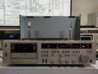
6LU8 push-pull amplifier

This one is my corona 2021 project, with 4 compactron 6LU8 tubes and one GZ34.
It is heavily inspired by a link I found somewhere on the internet:
http://web.archive.org/web/20130531160213/http://www.veiset.net/6LU8/index.htmlOutput transformers and choke are very cheap Chinese ones, power transformer is a Hammond unit.
1.JPG
2.JPG
3.JPG
4.JPG
6.JPG
7.JPG
8.JPG
a.JPG
5.JPG

Sounds really good with my Klipsch Cornwall III speakers.


Best regards, 968driver.

Hakko FR-301 is remarkable!!!

I recently purchased the Hakko FR-301 to complete a job that would have been ~impossible~ to approach / complete other wise. I do not know how I lived without this well engineered tool. It was very intuitive to learn, use and get familiar with the sound it makes (know what it is doing) while in use.

The Audio Research amp I was re-capping has nearly 2 foot long, 2 mm thick PCB. I was concerned about damage to the traces trying to get enough heat into the joint / through hole. I gave up on braid 30 years ago, have (and used) multiple sized de-solder bulbs, have several types of "syringes" and the iron tipped de-soldering tool.

It made (for me) a daunting task a breeze! With the Hakko narrow tip, I was easily able to get between the 10 film bypass caps without damage to them. The finished result "looks factory", the most difficult part was in matching the solder *art* work done by the factory... A SUCCESS!

Lastly, had I gone with a 2 piece station, (I feel) I would have been hampered in positioning and movement... but worse, snagging components, possibly heat-sinks on FETS (the horror of it) The 301 was very ~ e a s y ~ to maneuver and hold steady, in tight spaces... a sweeping contrast to the 2 separate piece iron / syringe. It would have been impossible to bear hug the massive chassis and tell where both hands were... a potential mess.

Help with crossover?

Hi all
Thanks in advance for any suggestions.
I tried to upgrade components in my PMC FB1 network and now have no HF.
The tweeter works fine, checked.
I checked for dry joints, breaks, damage etc, all fine
Checked resistors, fine
Checked inductors with continuity test, fine.
Desoldered and re fitted original comps, no change.

Something has gone wrong and I can't find it.
Can anyone suggest a method of checking the network using only a basic mm?

ty

Recycling - T/S Parameters Database?

I'm heavily into recycling, and loudspeaker technology hasn't particularly advanced in the last several decades. I'm toying with the idea of building a reclaimed driver database. The idea comes from commercial advances within the industry. There is no real market for small sub-woofer drivers. With the advent of micro-systems manufacturers were tasked with getting the maximum amount of bass out of the smallest possible driver in the tiniest of cabinets. (The fact that these cabinets are predominately ported is another conversation). The upshot is that any 4 or 5" bass driver in a micro-system speaker had a low Fs and Xmax to spare.

Now we are in a new commercial wave. The minions are purchasing wireless subs, throwing their old home theatre subs into the landfill. Without published T/S parameters the Air-fix crew won't touch them.

I have pulled the same driver from Sony, LG, Samsung, JVC, and Pioneer subs. I'm proposing a database to track these drivers.

e.g. Driver ABC1, used in systems: Sony32, Sansung11, JVC16, and Pioner23. TS Parameters:????

I think this could be a good resource.

Attachments

  • sub5.JPG
    sub5.JPG
    595.8 KB · Views: 129
  • sub6.JPG
    sub6.JPG
    454.3 KB · Views: 98

Running indicator LED from elevated heater supply

Hi All,

The power switch I am using on my amp has an integrated LED, as per below:

https://www.mouser.com/ProductDetai...3Li2QhXa0qUQ=&countrycode=AU&currencycode=AUD

I was hoping to operate the LED from the heater supply. However, my heater supply centre tap was going to be elevated to +35V, using a voltage divider hooked directly to B+.

I feel like this probably is NOT a good idea. While it would probably be fine most of the time, if there was some kind of component failure we could potentially see the LED being fed the full B+ voltage. Not a good situation given it is going to be touched when the switch is operated!

Interested to know if this is a legitimate concern or if I am just being paranoid. Presumably the switch has some kind of internal isolation, though possibly not for the voltages concerned.

Many thanks,

Greg

Help modelling synergy horn woofers in hornresp and xsim

So first off I should come clean and admit the cardinal sin of building someone else's design. That is trying to use an alternate driver, but first hear me out.

I am building this http://projectgallery.parts-express.com/speaker-projects/synergy-horn/

And having listened to the bass and lower midrange of the morel kw-1 and dayton dcs165-4 in sealed boxes I much prefer the sound of the morel

I know drivers can sound better in horn, but in a synergy horn or least this design the woofer don't see much loading until above 200hz.

Therefore I'm trying to use the morel kw-1 in the design and use the same mid and tweeter.
So far I'm trying to model the original woofer in the horn and compare this to the measured response from the designer. So far I've tried modelling the driver at the mouth and found this to have too big of a peak at 500hz, however modelling it as an offset horn I get hardly any peak as if their is barely any horn loading.

Anyone have suggestions? I've attached my hornresponse inputs and a .pdf of the project here. See post 153 here https://techtalk.parts-express.com/forum/tech-talk-forum/1331723-synergy-horn-build/page11 for the response I'm trying to replicate. All three drivers raw responses are in post 63.

1640671144913.png
1640671226781.png

Attachments

I am a craftsman. Speaker maker.

HI, I am a craftsman and from China. I have made the speaker for 30 years.
Full range speaker is my most product. Cone is made with paper. The paper is Handmade pulp. I think that is the way show top tone.

It is the first to diyaudio. Nice to meet you! I hope Communication speaker at here. My English is not very well. so type word should user tools to translate.
5.25 FW SPEAKER 1.jpg

https://www.ixigua.com/6942074875699954216

jojo

ATI (Linear X) LMS card for sale

For sale is a working LMS measurement card. It is Rev C and dated 8/8/91. No manual, software, or cables are included, however you can find the software and manual online here:
Downloads

You can make your own breakout cable. I recently tested this card by performing a loopback check in a friend’s setup and it functioned properly. Asking $500 + shipping. PayPal add 3%.

Attachments

  • 802005B4-5C07-47CB-96CE-FD462EE00005.jpg
    802005B4-5C07-47CB-96CE-FD462EE00005.jpg
    1 MB · Views: 361

When should one replace drivers?

Hi All,
I have a 2 way comprised of B&C 12NBX100 and DE500 and have been in daily use. These are now almost a decade old. Speakers are doing well, no issues. I was wondering if I should be considering replacing these drivers. The amp is now of the same age as well. I thought maybe replacing the drivers will bring back some magic lost over time. How much do drivers lose their performance over time? Is it worth the cost?

Phase splitter which tube?

Hello to all 😀

I would have to choose between some valves for a phase splitter
(For directly drive a couple of EL84 or EL34)

In Long Tail Pair it is better a hi mu or a low mu triode ?

12AT7
(Plate 250 V, 10mA)
u = 60
Ri = 10k Ω
gm = 5.5 mMho

12AU7
(Plate 250 V, 10.5mA)
u = 17
Ri = 7.7K Ω
gm = 2.2 µMho

12AX7
(Plate 250 V, 1.2mA)
u = 100
Ri = 62.5K Ω
gm = 1.6 µMho

Perhaps it would be better a low mu and low plate resistance as 12AU7 ?


Thanks. 🙂

Melos triode 200+ looking for spare parts

Hello

I own a melos triode 200+ stereo who had burned a transistor, probably because some old capacitors who altered the values, that now we replaced with some new ones. Unfortunately the data on the transistor are unreadables. We tried to replace the old transistor with other similar values, but with bad results (the sinusoid results cutted in low).

Please, somebody have the originals or can read the data on the originals to try to find them? Or can tell us the address of somebody who can know it?
We obviously can pay for spare parts and correct informations.
Thankyou very much in advance.
my email is zigozigo3@hotmail.com

The transistor is the one in the yellow circle.

Attachments

  • melostransistor1.jpg
    melostransistor1.jpg
    88.7 KB · Views: 714

New house with awkward living room

I moved into a new house and the living room is about 28X28X10 good size and my North creek D28 Borialis struggle to fill the room. The biggest problem is the left side of the room is open to the kitchen with a 4’ counter separating it as well as the entryway hall extending another 25’. This really messes with sound stage. I know any speaker will be a compromise but would like some advice what to build. I have a descent sub system and was thinking about a 8” full range with woofer assist. I wanted to build the pass Slob but OB probably would not work out with wife and room geometry.

thanks for any advise
Bill

Combination Cassette Tape Head

Hi and seasonal greetings from New Zealand.

Does anyone know a supplier of replacement combination cassette heads? I have been working on a Toshiba PC-X88AD, had transport issues and required a new Aurex chip but got it working fine and nicley aligned. Been sitting on the shelf for a couple of weeks now there is no replay on the right channel. Measured on the head the RH replay has no continuity.

Thanks.

Toshiba combination head.jpg

Simple 45 volt DC adjustable bench supply ultra quiet and simple

Here's a design I came up with out of necessity. It's simple/cheap/quiet/reliable.
I had designed an A/D acquisition sensor for my company that could measure voltages up to 60Vdc. I needed to test it with a known V source . It was difficult to find a finely adjustable bench DC source that would go that high without spending a lot of money so I threw this together and have since realized how useful it is for other projects. For example this can be used to supply power for any preamp design using a single supply. One could replace the pot with a fixed R.
It's probably not original but I did come up with it on my own just from past design experience.
The front end is a conventional toroid transformer/rectifier/filter. The output circuit implements a capacitance multiplier topology, which is essentially a transistor configured as an emitter follower with an RC to the base. The Hfe of the transistor effectively multiplies the capacitance. In the end it's as if you put the equivalent cap on the output of the rectifier. In this case I used a power darlington TIP142 with a gain over 1000. 1000 x 10uf = 10,000uf. So I have this appended to the front end rectifier filter which already has an 8200uf cap. Hence, It's ultra quiet with no visible ripple at half load which is about 1/4 amp.
The darlington is current protected using one of my favorite constant current circuits. Essentially a small signal transistor will turn on, shorting out the base emitter junction of the darlington, turning it off, when the 1 ohm series sense R develops 0.65v, ie 0.65 amps. It probably wouldn't survive indefinite duration short circuit due to heat/dissipation. One could always attach a simple thermal switch to the transistor heatsink. It would open up the secondary DC. The heatsink in this case is a piece of 1/8" thick 2 x2 angle aluminum that also doubles as a front panel.
Using a 10 turn panel mounted pot the output V can easily be adjusted in 10mv steps.
It is unregulated, If you need precise regulation add a voltage reference device and an opamp as the source for base drive.
I built a prototype with components on perf board mounted on a piece of 1/4" plywood. (Oh no! Call NFPA). I used proto board and a spring contact terminal block.
The PCB uses about $15.00 dollars worth of parts. External parts total about $45.00, the most expensive items being the transformer/10 turn pot/binding posts.
25 circuit boards from Exprss PCB would be about $325.00. If you eliminate solder mask and silkscreen about half that.
If there's any interest, I will put up a zip file with schematic/BOM/Express PCB layout file/Tina simulation.
Capture transient response.JPG
Here's the schematic and photo anyway.


IMG_0454[1].JPG

Voice of the sugar shack

Some pictures of my latest project: a couple of "hornflex" boxes. My own design but obviously very inspired by old Altec cabs from the late 40´s.

Attachments

  • votss2.jpg
    votss2.jpg
    66.5 KB · Views: 120
  • votss3.jpg
    votss3.jpg
    106.8 KB · Views: 121
  • votss4.jpg
    votss4.jpg
    75.8 KB · Views: 118
  • votss5.jpg
    votss5.jpg
    76.8 KB · Views: 119
  • votss6.jpg
    votss6.jpg
    71.6 KB · Views: 117
  • votss7.jpg
    votss7.jpg
    57 KB · Views: 121
  • votss8.jpg
    votss8.jpg
    51.3 KB · Views: 114
  • votss9.jpg
    votss9.jpg
    72.3 KB · Views: 116
  • votss10.jpg
    votss10.jpg
    58.6 KB · Views: 124
  • votss1.jpg
    votss1.jpg
    72.2 KB · Views: 121

FS: Technics DVD-A10 DVD Audio/Video Player

Uncovered another forgotten disc player while going through stored audio equipment. The Technics DVD-A10 DVD Audio/Video Player was pushing the envelope to optimize playback of the new DVD Audio format. While Technics succeeded, the DVD Audio format did not. Luckily, this is a very fine CD and DVD player with superb audio. Build quality is excellent! This player is in near-perfect condition, lightly used and has been in storage for over 10 years. Please read this review on EnjoyTheMusic.com for more info.

I'm selling this superb player with 4 DVD Audio discs for $150 $100 $75 to continental USA buyers only. Buyer will pay UPS Ground shipping chargers. Please PM me for more info or any questions.

Attachments

  • IMG_4253.JPG
    IMG_4253.JPG
    601.9 KB · Views: 577
  • IMG_4254.JPG
    IMG_4254.JPG
    653 KB · Views: 432
  • IMG_4256.JPG
    IMG_4256.JPG
    721.8 KB · Views: 269
  • IMG_4271a.JPG
    IMG_4271a.JPG
    380.5 KB · Views: 280

Vents in a horn sub ?

Hi, I love the impact and dynamics of horn, but to get to 40 hz they get pretty big. So I was wondering, if it is possible to put vents in a W-Horn like this

W Horn.JPG

or would I lose the compression and therefore it does not function like a horn anymore.

I found a picture where it seems that idea is applied

W horn  med reflex.JPG

Would certainly be nice to get the lows hornloaded through the vent. But then it would have been done decades ago, I guess, so maybe there is no such thing as free lunch😉

Regards Sebastian

Working with SMD. How to do it without specialised tools.

Something I have been meaning to do, put down in words and pictures how to work with surface mount components. This is a technique I developed years ago when SMD first appeared and we hadn't the luxury of re-work stations etc.
These pictures show how to remove a "postage stamp" I/C. Timewise it would take me around 6 or 7 minutes to remove.
First picture shows the tools used. Nothing special, just a good iron and braid and a jewellers screwdriver that fit well between the legs of the IC.

Attachments

  • imag0001.jpg
    imag0001.jpg
    48 KB · Views: 2,542

Pair of Peerless P830549 NOS Passive Radiator

I have a brand new pair of P830549 Peerless XLS 12' passive radiators that I purchased to make a pair of subwoofers.

I have been unable to find a pair of matching Peerless 830500 XLS 12"woofers. I had previously built three such sealed subwoofers and use one every day for my home theater system.

These are for sale to someone who can give them a good home. Make on offer!

-david BTW

P.S. I built the original design based upon a Peerless application note but tweaked by George Short of North Creek Music as the Thunder Product.

Attachments

  • IMG_1296_0055.jpg
    IMG_1296_0055.jpg
    883.8 KB · Views: 369
  • IMG_1297_0056.jpg
    IMG_1297_0056.jpg
    887.8 KB · Views: 471

Finally: The QUAD II and QUAD 22

Dear Forum!


After some years of thinking about those units, I've finally bought a set of mine.
These are coming from the UK (from the only and the first owners) the preamp from a different source, but also in a very good state.
All the three looks fairly well cosmetically, un-abused and free of any rust. Tubes are factory ones in the IIs, but not original in the 22's (one Brimar three Mullards, one of them from Holland)

My plan is to use them with my QUAD ESL 57's, but as they are in an untouched, factory condition, I am sure they need a huge refurb.
As far as I know from some respectable forumers here at Hungary, that the end-amps are something those are really sings even these days in a modern setup, but preamp has rather a museal value than a real use-value as they are inferior in quality for HiFi, but I want to use them, together, as they are a set, and I would like to have an as authentical system as I could possibly have.

So far, I have found a lot of information regarding these amps, so I decided to refurb them (or rather just have them set up) by myself.
My questions are, if it is possible to have these repairs at home by me, who's have only a marginal knowledge regarding the subject, but having good soldering skills, a DVM, a cap checker, a 100W light bulb, 230V mains and a registered profile at Mouser and eBay?

Thank you for your answers, help and encouragements in advance! 😉

Old gear: What’s that varnish/laquer?

Hi friends, and post-merry-christmas to all 🙂
I recently found a picture of an old film-projector, and was reminded of other technical gear where this coating was used, it is a structured coating, giving the piece a stunning technical beauty, looking really nice and got me wondering what stuff this could be? Didn’t find anything in this direction 😢…
Anyone has an idea of what this is/was?

https://shikan.org/MovieCameraCollection/moviecamera-3_041.jpg

thank you

class d tri angle 555 step by step by foodland

this circuit use ne555 gen tri-angle 400khz

Attachments

  • 265904681_1251691361976209_1477927957990063552_n.jpg
    265904681_1251691361976209_1477927957990063552_n.jpg
    155 KB · Views: 187
  • 265962973_454835422662670_6025741732574330449_n.jpg
    265962973_454835422662670_6025741732574330449_n.jpg
    117.3 KB · Views: 207
  • 266335540_4611927992225419_990061036339089222_n.jpg
    266335540_4611927992225419_990061036339089222_n.jpg
    89.4 KB · Views: 217
  • 266289362_1112510956174077_4185127080228636291_n.jpg
    266289362_1112510956174077_4185127080228636291_n.jpg
    97.7 KB · Views: 191
  • 266389611_509791093474257_7104265762823534453_n.jpg
    266389611_509791093474257_7104265762823534453_n.jpg
    95.9 KB · Views: 169
  • 265771180_622866262292429_4181169005048205786_n.jpg
    265771180_622866262292429_4181169005048205786_n.jpg
    152.8 KB · Views: 162
  • 266347422_690463855652685_6407712116307720166_n.jpg
    266347422_690463855652685_6407712116307720166_n.jpg
    90.5 KB · Views: 163

Mar-Kel70 in Sweden

This thread split off from here http://www.diyaudio.com/forums/full-range/85410-metronome-75.html#post2145622 :cop:

How do i do it myself?
Yeah, i am thinking of a Lotus. And the thing that it is possible to put in one more driver whenever i want is pretty cool aswell. But will they work well in my room and is it good to have the subwoofer to take care of <150hz or something like that?

DIY Princeton amp input resistor?

A while back I've build a Princeton. Sounds like it should, not getting any RF noise but today looking at my schematic I've noticed I've used 33k input resistor on my single input socket instead of the 68k on each of the two input sockets as the original has. Without opening it up I wonder what the difference between 33k vs. 68k might make if any at all? I wonder how critical this resistor actually is since some vintage amps never had one in the first place. Perhaps it's only important for high gain 1st tube distortion setup which Princeton really isn't?

Turn on the lamp LED late to enter the voltage

Hello all .
I need the help of a specialist in a department based on the following:
I have a voltage ( 12V DC) through which I turn on a lamp (LED) as soon as the voltage enters the lamp it will glow, what I want is to have an electronic circuit that the voltage enters and after a minute of entering the voltage the lamp ( LED) glows. And it stays glowing. In other words, I want to delay the timer for the passage of voltage to the lamp.
Any help thank you.

Attachments

  • 9999.png
    9999.png
    3.5 KB · Views: 110

6S33S Push-Pull designs that need an OPT?

I have all the major parts necessary for building a push-pull amplifier using the 6S33S tubes. I have multiple power transformers, chokes, and even a pair of Toroidy TTG-6C33CPP output transformers. I want to make the best possible circuit that uses the 6S33S tubes and uses these output transformers. What options are out there. Before anyone asks I am not interested in the OTL amplifiers For this project. I will build one in the future but I want to try a more conventional amp first.

Thanks in advance.

WAW Bluetooth speaker (Monacor/Wondom)

Hello,

Did build this bluetooth speaker with drivers I had on hand from another project :

  • Monacor SPH200CTC (8" dual coil)
  • Monacor SPX-31M (2,5" full range)

The bluetooth/amp section is powered by a Wondom (Sure electronics) JAB4 with 1701 DSP.


About 7,2 net litres for the woofer (plus stuffing to reach the optimum 8 liters), crossover at 204Hz because I feared for the life of the SPX31m. 1.5 litres for each full range.

- First manual equalizer (15 bands) iteratively measuring with UMIK-1, various Q
-- Lots of boost from 30 to 60 (which was foreseen with simulation)
-- Q=8 Bumps to correct at 32Hz (High bump) and 38Hz (Low bump)
-- Shift of the response curve around 10k (SPX31M suddenly looses 8db at 10k)
-- Bumps around 4k,8k,...
  • Then second equaliser with 6 bands to make it taste to our like
  • Finally bass/mid/treble controls which are very welcome because line-in and bluetooth do not show the same response curve (bluetooth has more mids)

Equalizing done with grille on the speaker, impact is noticeable.


SPX-31M is not the one I would have chosen but with EQ we are already a step ahead from a Marshall Woburn that we could test on the same music (various), much more cleaner bass, very strong attack.

Cabinet are closed: bass reflex would have required a few more litres I don't have due do size (427mm x 300mm x 15mm including grille).


This is my first project with a DSP (Sigma Studio) and I'm quite surprised how this little chip can save a less than ideal response curve (form factor was not negotiable).


Was thinking about the Fountek FR58EX to replace the SP-31M, any advice on this little full range ?

François

Attachments

  • IMG_7745.jpeg
    IMG_7745.jpeg
    107 KB · Views: 145
  • IMG_7743.jpeg
    IMG_7743.jpeg
    66.8 KB · Views: 117
  • Like
Reactions: ZMathers

Hafler JF2000 / Rockford RF2000 mods...help!!

Hello..... new guy here. I own a Rockford RF2000 amplifier... yes, it's home audio. It's identical to a Hafler JF2000, but harder to find. I would like to upgrade/modify it. Does anyone have suggestions? I am including a link to the schematic....PDF was too large to attach. I contacted a guy that does some work on this stuff..... he suggested that I replace the NE5532 opamp chips in the input stages with Burr-Brown OPA2134 chips and that I replace the 47uf/100v caps on each output stage supply rail to the "largest caps that will physically fit the spaces". Does anyone have suggestions?? Thanks a million!!
s9.quicksharing.com/v/8943762/RF2000_schematic_1_.pdf.html

Thorens td124 in need of help please

Hi
I’m new to this fine forum.
i have a Mk1 Thorens TD124.
But i guess this is why I’m here for a bit of help of guidance
when the turntable is plugged into mains 230V , not turning ie the selector is 0.
I have the biggest mains hum through the speakers
i removed the tone arm from the table and the amp
got my multimeter out and measured 110 volts from earth to the deck,

my guess is its got to be the motor that is shorting out.
if i select a speed it runs perfectly and the voltage drops to 44 volts

obvs i disconnected the amp as soon as i heard the horrible hum

Any ideas folks

A "Sound Technology 1200A Test Panel" that needs attention.

I restored the power supply, Deoxed the pots and switches. Replaced the RCA jacks on the front and resecured all the BNC connectors on the back.
All the PS voltages are good.
I have the panel connected to the ST1700B and a ST1000A along with the Bench receiver.
At first the test panel was working well. I connected each ST Distortion analyzer, FM generator and the Oscilloscope, making sure the switching and functions worked through the panel.
I have a feeling the op amps are making it difficult to precisely check the functions. Sometimes the signal is there, other times its distorted.
Its the buffered signal that the ST1200 uses for all the test functions where a signal is needed in the test receiver/amp.
It has some of these OPA2605 and the OPA741's there's 14 or so op-amps total in this piece of equipment. I need to find some modern op amps to fit.
Here's an attachment of the snip: test signal board:

Attachments

  • st1200 test mesurement board 1.PNG
    st1200 test mesurement board 1.PNG
    327.2 KB · Views: 327

Power Draw Using Current Limiter & Amps

mains power is 120v 15amp
am using a homemade 250w bulb current limiter, series hot side iirc.
also inline is a cheap consumer level watt meter

Marantz sr18 plug into this draws 60w at idle and does not cause bulb to glow / only slight heat if any.

Harman Kardon AVR7300 plugged into this draws 125w at idle and bulb glows solid orange is HOT. AVR plugged in without the bulb current limiter the power draw is 150 watts at idle.

was using the Harman as main amp, and regular is used at volume.

Wanted to try out dying Marantz (only amp section works) and after this test am shy to use the Harman Kardon.

Any ideas what this means; if not obvious from above I know little to nothing about EE stuff.

Also the power draw when using the marantz even at low volumes I see it goes up a bit in watts, so I guess it's much less class a watts, and the harman is more class a watts comparatively (has hgh idle in spec sheet comparatively) but that glow bulb with harman tells my limited experience there is a mild short somewhere.....i think lol oh and is strange to me that power draw goes UP without the bulb current limiter. Is that difference in measure (25 watts) the amount of direct short within the harman kardon?

maybe am answering my own question, but do not have another heavy class a or all class a amp to see if it makes bulb glow more than the sr18

Harry's "Dayton Im a sumo sized soundbar"

Harry's "Dayton soundbar"

Hello DiyAudio forumites, this is my first post on here... G'day from Australia 😀


Im looking at building and BT soundbar/boombox for my metalwork/car workshop, it needs to get reasonably loud and sound nice(better than a cheap plastic thing).
I've done a little bit of speaker building before and done a few car audio installations in the past(My own and mates systems, full custom builds) and I'm also into making furniture, so physically constructing them is no problem.


I have already purchased my drivers and amp they are,
Dayton ND25FW-4 for the highs
Dayton RS180-4 for mid/mid-bass
Dayton RSS265HF-4 for the low end
Dayton DTA-2.1BT2 amp


I was intending to make a large "Dayton" soundbar all in one solution that can be used for my workshop of course and occasionally for party background music so some portability is desired... even if it takes two to carry it🙄


As you would guess by my driver list its going to be a 2 way with sub, I will need some direction on the xovers for the ND25FW-4 and RS180-4, Im trying to learn as much as I can on them so far I think a xover around the 3k point, Dayton suggest keeping above 2.5k for the ND25FW.
I've tried to model the xovers in the excel sheet by JB after following Toid123's tutorial on YT, still playing around with it so I will have some questions to ask later when I go to finalise them as Id rather complete the box design first so I can include a bafflestep correction.


The box(s) design so far I have used Winisd and come up with,
Sub box vol is 50ltrs double slot ported @30Hz
Mid boxes vol is 15.4ltrs single slot ported @44Hz
The design is a box 300x300x675mm internally for the sub and 300x300x203mm for the mids, these volumes include vol for drivers ports and some bracing.


So here's my 1st question, looking at the picture below you can see its going to be sumo sized soundbar at about 350x350ish mm by around 1200mm long(14x14x48" approx), as all the drivers are on the same baffle how will this effect bafflestep and will it cause any bad cancellations? Is this design a bad idea can you see any major problems with box design and/or driver selection?

Attachments

  • Snipaste_2020-01-15_17-45-11.jpg
    Snipaste_2020-01-15_17-45-11.jpg
    104.6 KB · Views: 760
  • Snipaste_2020-01-22_16-13-12.jpg
    Snipaste_2020-01-22_16-13-12.jpg
    124.5 KB · Views: 749

Another Sony TA 4650 V-fet thread

Hi all,

Another thread on this Vfet amp – this one was known to be deceased from when bought from E-bay. However, through a well-trodden tale of woe, I have a set of V-fets for it, just a case of figuring out what caused a problem in the first place,

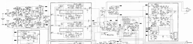
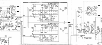
First of all – service manual, I have refurbed a TA5650 previously and you can download plenty of V-fet information readily. You may have to have several goes before you find a really clear copy, but you are looking for the service manual and any bulletin you can find, either for the TA4650 or the TA5650.

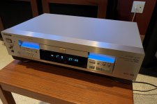
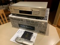
Second of all it arrived! Since the seller gave no useful information on what or why it wasn’t working I figured check Vfets – heck I MIGHT be lucky

Yeah, I wasn’t 🙄

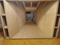
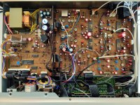
Not 100% sure that they, the V-Fets hadn’t been disturbed, for all I know at this point the amp was bought to salvage a set of transistors, as otherwise the internals are ( I’m 99% sure) completely un-touched and a reminder that more people smoked in the 80’s. Nothing burned and no obvious failures like a bulged cap or burnt resistor.

I'm intending to write this up as I go for information. This tale might not have a happy ending. But I have a dead 5650 and a dead 4650 to go at as well as what seems to be a set of V-fets

All the gear and no idea


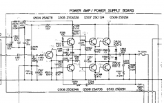
Step 1 then: where does this fit on the Sony development cycle? These amps had at least one major update it seems, to try and reduce their propensity for self immolation. This example will need the fitted 1.5k, ¼ watt resistors R313, R314, R363 and R364 exchanging for 3.3k on the Power amp (F) board. DC bias was probably set at 75mv too but that’s irrelevant as it’ll be re-set later.

OK Party time at RS components, or your preferred parts peddler. £$£$£ add .gif of throwing cash...

I’ll take each board in turn at this stage, but my rules of engagement are:

Cap values – same, I believe the V-fet amps have to wake up in a certain ‘order’ from what I’ve read so I’m sticking with Sony’s values. Plus it’s nice to know that the character of the amp will be preserved. The only real gripe is that the power supply caps on the TA-4650 are 4700uF whereas on the substantially similar TA5640 they are a whopping 10,000uf. I had planned to split the difference with 6800uF but ultimately I bottled it – your first explicit invitation for “Comments Please”

Cap voltages – a variable; I figure that capacitor technology must have improved since this was built and I’m not trying to save every penny so if it fits and is a bigger voltage I’m ok with that – to a point eg a 10v cap might become a 25v cap of the same value.

Cap Types
Frankly, 0.47uf is not a value I associate with electrolytic capacitors and even 3.3uF is a push so these are going to be switched to polyester types. Same for C351 and C301 (10uF/16V) as they sit I the audio path. Equally, where available I prefer polymer types over electrolytic. That is MY preference your science may vary. Don't grumble, whatever, 40 year old etc...

Resistors
Just normal ¼ watt types nothing fancy, nothing fancy coming out nothing fancy going in. But they are checked if it says 3.3k it better measure that before soldering.

Final disclaimer, any specific components referenced are my choice, and probably based on the flimsiest of logic..

Sooooooo…..

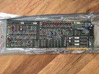
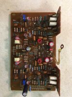
Board 1 – power amp board (AKA the F board)

Pre-power on aims:

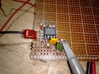
FIRST replace the so-called ‘death diodes’ VD1221 with 2x 1N4148 there are three on the Power amp board D414, D352 and D302. The latter are thermally mated to the transistors next to them, I’ve read both, that it’s worth doing, and it’s not worth doing. Sony did it, and it would have been another step in manufacturing; ergo, why not?

As a side note I’ve not yet come across a bust VD1221, maybe if they got this far they’re ok? I'm four amps in at this point

All Electrolytics will be replaced. Come on, this thing is more than 40 years old. Let’s just assume a component with a rated hours life time is past its best! (As I am slightly older than the amp, let’s also give thanks that this logic doesn’t extend any further, Oh hang on a minute…)

Not many capacitors really:

TA-4650 - F board
Qty old Value voltage New Value Voltage RS
C417 1 0.47uF 50v 0.47uF 63v 108-2429
C301. C351 2 10 uF 16v 4.7 uF 63v 171-9241
C306, C356 2 10 uF 16v 10 uF 25v 714-9622
C307, C357 2 10 uF 16v 10 uF 25v 714-9622
C303. C353 2 100 uF 10v 100 uF 16v 839-2341
C305, C355 2 220 uF 6.3v 220 uF 25v 839-2180
C418 1 10 uF 25v 10 uF 35v 839-2316
C420. C421 2 100 uF 50v 100 uF 100v 571-650
Cap count: 14

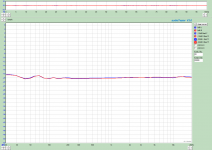
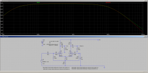
Note especially C301 and C351, are the electrolytics in the signal path!! So changing to ‘not that’ makes me feel better. The 4.7uf value doubles (?) the L.F. cut-off point but it seems that Sony buried it in the dirt to begin with, sub 1.5 Hz still feels OK, but we haven’t listened yet 😀

At this point there are no guarantees that this will actually work, come power up, but since these mods will happen anyway my logic is to simply remove variables before that point. Less likely a problem will be a bad cap if it’s a new cap!

Bias resistors RT301 and RT351 won’t have moved in years and again there’s [STILL] that smell of tobacco so I picture a thin film of Marlboro in the resistive layer – and goodbye. To be replaced with your favourite VR no doubt, but in this case I chose Bourns 2.2K multi turn trimmer 3296Y-1-222LF or RS no 785-9767.
Interestingly measured resistances on the old pots were close to mid-range (bagged and tagged for later examination if needed)

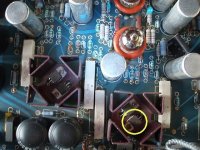
R423 which forms part of what appears to be a filter network has got hot at some point, at least enough to burn the markings. On removal it measured 1.4k rather than the 1k value it’s supposed to be. So I’ve swapped out for a ½ w 1k. Hopefully that was the right thing to do… Worryingly it’s a resistor that will see some pain if transistors fail on the input side

Pretty happy with the amp (F) board at this point, just a little nearer powering up.

To be continued....

Attachments

  • thumbnail_IMG_6936.jpg
    thumbnail_IMG_6936.jpg
    282.1 KB · Views: 771

Which benchtop DMM to buy?

Having the intention to buy a bench top DMM (mains supply as advantage so it can contineously be "on") because it is the only one which also include inductance measuring.
This for a reasonable price. Does anybody has gathered some experience about this DMM?
Or, can somebody recommend another one in this price range? (Must include L- measurement possibility).

CHN110 voigt bipole idea

I'm contemplating an adaptation of Scott Lindgren's voigt pipe for the Mark Audio CHN110, last one on this page: https://www.markaudio.com/wp-content/uploads/2019/12/CHN110-with-plans.pdf

Could it be worthwhile to make a b/dipolar version by building a cabinet double the width (i.e. two identical, separate pipes side by side) and mounting a second driver on the back of the 'additional' cabinet?

Why? I like the 3D effect of bipole /dipole speakers + need the paralleled drivers' extra sensitivity + it would tackle baffle step and improve bass output.

I would place the rear driver as low as possible (see https://www.hifizine.com/2010/06/the-controlled-pattern-offset-bipole-loudspeaker/), but how low can I go without messing up the voigt pipe's operation?

Given the cabinet's fixed dimensions, could I just play with the vents' length and diameter to tune bass?

Lastly, I could wire in a bipole/dipole switch to hear which works best.

Curious whether this seems feasible...
Simon

Harman Kardon CD491 output level adventures

This deck was too dull on Dolby cassettes. Either B or C. Owned by a collecting friend but this one he could not succeed aligning for the life of him. Capacitors renewed, contacts cleaned, mechanism & heads inspected. M300 gauge pass, full track test cassettes pass, the works.

After he went by the SM few times with no positive results, in a final act of desperation he tweaked every trimmer and coil in case he could find a clue by luck. No miracle happened.

He finally brought it to me before written off. I first tried by the book (SM 66A + 66C) to make sure he did not skip or screw some important step but no, still dull as mud.
Then I thought of an alternative scenario to try and it worked. Either I am a lucky unorthodox, or something has drifted badly in the particular unit, or some crucial piece of information is lost between production versions and service manuals revisions available online.

Anyway. Sound with Dolby is now normal against his Nak CR-7, Nak RX-505, Revox B215, and he is happy. On commercial B NR tapes and on recordings back and forth between his different decks with B,C NR.

In case someone stumbles on the same problem with this version deck, but without a better SM conforming solution, my notes are:

R353,R310=470R+470R divide HA12058's output (p24,p25) with VR301=5k to ground i.e. output at the RCA is x0.84 (5k/5.94k)*

The user manual states 420mV output. 1/0.84=1.19
420*1.19=500mV original signal from the Dolby chip
It doesn't compute with 580mV TP in the service man

Wait, Nakamichi smaller decks had 0.5V straight output
Maybe they revised to compete in showrooms with that

Nak test tape is 0.917*ANSI or 1.09 weaker (218/200)
500mV*1.09=545mV is analogous with ANSI level tape

Modified settings:

-Playback level set ~550mV on the output RCAs with an ANSI 400Hz Dolby level test tape, output knob at max
-Peak meter set at 0dB for ~550mV (545) output on 38mVRMS 400Hz input, REC level knobs & Master at max
(the meter trimmers are located under a bottom hatch)
-Internal oscillator set for 55mV bias tones & 550mV rec cal tone at the output RCAs

*This deck is sensitive to output loading, has no buffer circuit at its output. Notes are taken at a high 1MΩ load to be neutral
There could be 0.5 dB difference in optimum output setting due to heavier loading. Down to 520mV probably. Worth exploring

-Adjust RecCal and bias vs Level & FR. Try for alike result when using NR and not using NR
Use neutral response tapes for base bias so the fine trim knob acquires symmetric enough range

Attachments

  • hk491_bench.jpg
    hk491_bench.jpg
    520.2 KB · Views: 464
  • hk491_open.jpg
    hk491_open.jpg
    950.1 KB · Views: 511
  • hk491_hatch.jpg
    hk491_hatch.jpg
    741 KB · Views: 326
  • hk491 Basf Ferro I-Sound  no Dolby.png
    hk491 Basf Ferro I-Sound no Dolby.png
    15.3 KB · Views: 333
  • hkcd491_partial _sch.png
    hkcd491_partial _sch.png
    310 KB · Views: 245
  • hkcd491_partial2 _sch.png
    hkcd491_partial2 _sch.png
    440.4 KB · Views: 251
  • Like
Reactions: katopis

APT Holman preamplifier problem

Hello Guys,
As some of you may already know, I've got my late brother Apt Holman preamplifier. It has gone through an chemical caps change and some repair (the phono entry died on me because of a faulty transistor).
Today I discovered that the "Stereo Mode" is behaving strangely.
If I turn the pot fully CCW I've sound on both the left and right channels.
If I turn the pot fully CW I've sound only in the left channel .
So IMHO this device has a fault.
I would very much like to hear from you about the probable cause before opening it.
Many thanks in advance for your answer !
Have a nice day and stay safe !
P.S. : If I'm not mistaken, turning this pot CW should SUBSTRACT left from right channel so if the input is mono, no sound, and if stereo, a "faint" sound on both channels from the part of signal common in both channels. If I turn this pot CCW, this should ADD the left to the right channel so a higher volume perhaps but nothing more than that.

DIY panels: Armstrong USG drop ceiling tiles

I need frugal acoustic treatment ideas. After looking at a number of DIY options, I think the best option might be panels made of acoustic ceiling tiles. The basic, low price tiles readily available at home improvements stores are made of compressed fiberglass or mineral wool, and painted with latex paint. They come in a convenient sizes 2' x 2' or 2' x 4', and are fairly rigid and lightweight. The panels have published NRC data. Found this fairly detailed test result. Summary Table of Armstrong acoustic data. Here is another one: Armstrong Optima. More data (very comprehensive, worth pdf printing saving). The better NRC panels are thicker (usually twice as thick), but the same basic material (sometimes more environmentally friendly, Armstrong Lyra PB, for example). The front cover of the high NRC panels is more sophisticated than latex paint, and might be perforated plastic sheet, for example. But, they are exponentially more expensive, need to be special ordered, and sometimes require palette-size minimum quantities. Does anyone have experience with the low cost panels? YT "Tech ingredients" tested them, and said they test "about the same" as Rockwool insulation. The published sound absorption tests have profiles that appear very similar to professional acoustic panels. Can one simply stack panels to improve bass performance? I can envision stacking several panels to use as even bass traps, and either gluing the panels together or framing (wood frame or maybe edge-applied glue/paper-plastic tape/thin fiberboard) for mounting on the wall. The panels are covered in latex paint to contain the particles, and should be reasonably safe. I imagine they could even be used as the absorptive material in DIY RPG-like diffusion panels (e.g., modelled after Dado seems fairly straightforward). Any experience?

Quad 44 Tone Control Problem

Hey all! I recently refurbished a Quad FM4 (thanks @johnmath !) that came with this 44. This one also had some faults.
When the tone controls are cancelled out the channels are balanced and fine. When they're activated I get excessive bass out of the right channel, whilst in the left one it lowers considerably. The right channel is affected by the bass switch whilst the left one is completely unaffected by it. All the other tone controls works fine for both channels. Basically, compared to my other 44, it seems I get double the bass out of the right channel with the tone controls activated, whilst it seems the bass is at its lowest out of the left one.

I have performed a full recap of all electrolytic & tantalum capacitors. I have cleaned all switches and potentiometers. I wonder if the switch itself is defective. Anyone has any idea where to look? Cheers for any help pointing me in the right direction.

Pioneer TS-C132PRS / TS-C172PRS: Best active Crossover Points ?

Hi, this is Christian.

I need your help with the 2-way Pioneer speaker systems TS-C132PRS and TS-C172PRS.

In Germany Pioneer Car audio components are not so polular and because of that I can´t get the information I needed. I hope someone of you can.....

I want to run these Speakers with an active crossover (Linkwitz-Riley, 24 dB) for a front system.
The original passive crossover from Pioneer has a crossover point about 1900 Hz. In my opinion this is very low. I only found a russian test of the 172PRS and a review at Crutchfield ("tends to muddy up the upper-end vocals when at higher volume. I suspect this is why the crossover transitions to the tweeter around 2,000 Hz. ...the tweeter is crossed over so low in the passive crossover that it can get a bit stressed....)

I don´t know if it´s important, the speakers will be installed in a Mercedes C-Class (W202), Tweeters positon: A pillar.

Can you tell me the best crossover point for each of the systems ?

Thank you yery much !!!

Best regards from Germany
Christian

Purifi Amplifier with high end Buffers / Hypex HPR voltage regulator OPA1656 DIP8 Europe only

Hi amigos,

I am selling my personal Purifi Power amp made with care and great materials like new !

Buffers are Custom with HPR voltage reg. and made with Sumusu Japanese resistors and Nichicon KZ Muse caps.
OPA1656 or 1612 DIP8 socket to your own
Soft Start circuit to avoid inrush current and allow standby mode
Cooper banane plugs Viborg type
Cable speakers Blue Studio version UPOF
SMPS1200A400 shielded with a cooper film
Galaxy case made in Italy

Absolutely dead silence, fantastic sound stage (better than the Audiophonics Purifi and Nord and my other Italian Purifi amp)
Can drive any speakers easily.

Measures : 1W, f=1kHz 0.0007 % 10W, f=1kHz 0.00026 % 100W, f=1kHz 0.00015 % 1W, f=20-20kHz 0.0007 % 10W, f=20-20kHz 0.00029 % 100W, f=20-20kHz 0.00017 %

Spec : PURIFI 1ET400A modules X2
PSU Hypex SMPS : SMPS1200A400
Galaxy alu case
Power 8Ω : 227W
Power 4Ω : 425W
Power 2Ω : 450W
A-weighted 4Ω 131 dB
SNR A-weighted 4Ω 131 dB
Buffer GAIN: 14 dB
BANDWIDTH: 2 Hz - 150 kHz
SLEW RATE: 24 V/uS
CMRR: > 100 dB 60 Hz
INPUT IMPEDANCE: 47 Kohm
NOISE AND HUM: 6 uV

Free shipping to Europe.
Amp is like new.

PRICE : 1190 euros shipped

Please send me message private if interested.


Hafler 220 DC Offset Issue

I'm sure this has been covered somewhere but after searching I came up with nothing.
I pulled my old Hafler 220 off the shelf while overhauling my ST70. I popped the cover and rechecked bias, both channels fine at 277 or so. Left channel offset is fine at 2-5mv. The right channel is right around 200mv at startup and slowly comes down within range after about 10 min. Everything on the PCB is original. I just ordered new electrolytics from Mouser along with a couple of new films to replace the input caps. Does anything obvious come to mind that may cause this offset issue? The amp works fine and sounds good otherwise.
Thanks

Audio transformers chat channel.

Hi there tube enthusiasts,

I have designed, built and analyzed over 150 Audio transformers projects, consisting of mostly output, line-in, interstage transformers, chokes and power transformers. And I'm happily creating a Discord chat channel that will be based on Q&A on Electrical aspects on Transformers for audio purposes, where I will be happy to answer you a variety of answers related to this topic.

You can visit the channel via this link: https://discord.gg/FT26dQzywB

Just keep in mind I will be randomly available throughout different times of the day, 8 to 10PM CET Time zone.

Best regards,
Alexander.

Yamaha Receiver (RX-500) in protection - DC on Right Channel Output

Working on a nice old Yammy receiver. Relay won't click - it's in protect. Measured normal DC offset on Left channel (10mV). Right channel is showing +20vDC which is obviously why it's in protect. Pulled the two output trannys on the R channel (2SC2579 & 2SA1104) and it now comes out of protect. But, both test fine out of the unit - no shorts. The drivers also test fine.

I have worked backwards measuring the various transistors on the right channel and the incorrect voltage tracks back quite a ways. But I'll be damned if I can find the culprit. These are the voltages as per the service manual and what I'm measuring:

Manual: B / C / E // Measured: B / C / E
Q202: -11 / 0 / 0 // -11 / 0 / 0
Q204: 44 / 43 / 44 // 45 / 45 / 45
Q206: 0 / 43 / 0.5 // 0 / 45 / 6.0
Q208: 0 / 45 / 0.5 // 6.0 / 45 / 6.0
Q210: 44 / 18 / 44 // 45 / 0 / 45
Q212: 44 / 1.1 / 44 // 45 / 21 / 45
Q214: 0.5 / 1.1 / -1.1 // 19 / 21 / 19
Q216: 1.1 / 45 / 0.5 // 22 / 45 / 22
Q218: -1.1 / -45 / -0.6 // 19 / -45 / 20
Q220: 0.5 / 45 / 0 // 21 / 45 / 21
Q222: 0.6 / -45 / 0 // 21 / -46 / 21

As you can see, things start to go off at the emitter of Q206. Any help would be appreciated. Thanks.

Attachments

Soundstream Reference 405 (NON S/SX)

Soundstream Reference 405 (NON S/SX) Rectifiers

Working on a NON S/SX version, Soundstream reference 405. This NON S/SX version is using the 'rare' dual doubler rectifiers (The ones where the diodes both point to the right).

I need to replace the entire set as one of the BTs failed.
D103 through D106 originally is using FED16BT. This side runs +-25vDC rail voltage to channels 1 thru 4.

D107 and D108 is using FED16FT. This side runs +-35vDC or +-45vDC to the 5th channel subwoofer depending on physical switch mode between High Current or High Power.

FED16BT and FED16FT are hard to find, except for one place on eBay from Originalparts seller, who sells equivalents:

FED16BT --> FED16CT
FED16DT --> FED16FT

Will FED16FT work for everything or should I buy sleeves of both FED16FT and FED16CT? Would love to buy enough so I don't get another headache later on.

Question on Aging Capacitors

Hello All,

I have a Creek Classic 5350SE integrated amplifier dating from 2007 that has been in daily use. A few days ago, the motorized input selector switch stripped it’s gears, and is no longer functional. I am considering rehabbing the unit by removing the motorized switch and replacing it with a manual switch. However, I estimate that the ten 2200µF power supply Al electrolytic capacitors (Samwha brand) have over 40,000 hours on them. I have done a little research, and find that is about the service life of such capacitors. Therefore, I am thinking that attempting a rehab is a waste of time and money. Any agreement or disagreement?

Cheers,

ceulrich
Projects by fanatics, for fanatics
Get answers and advice for everyone wanting to learn the art of audio.
Join the Community
507,796
Members
7,888,829
Messages

Filter

Forum Statistics

Threads
406,261
Messages
7,888,829
Members
507,796
Latest member
MAYA MAJIMA