Driverack 260 - backup user presets

Hello,

is there any easy way to backup my user presets of driverack 260? I guess that once the bios battery dies, all are gone. I am deciding between writing all settings on paper as a backup and finding out what this outdated parallell interface on back of DR 260 can do. I do not even have a computer where I could connect this to, so I d need some kind of USB converter... oh boy...

Germanium Transistors! Help!

I need help with the datasheet of NTE102A and NTE103A. Attached is the datasheet.

Everything looks fine, except one thing : the datasheet says :

1.

" NTE102A (PNP) & NTE103A (NPN)
Germanium Complementary Transistors
Medium Power Amplifier "

2.

" Common-Emitter Cutoff Frequency, fαe, at VCB = 2V and IE = 10mA : 10KHz "

CAN YOU, PLEASE, EXPLAIN POINT 2. HOW CAN AN AUDIO TRANSISTOR HAVE A CUTOFF FREQUENCY OF 10KHz IN ANY CONFIGURATION AT ANY CIRCUMSTANCES?

Also :

I am extremely interested in Germanium transistors. I have found AD161 and AD162 at AliExpress, but, these are 20V.

1. I would take any NPN and PNP, even, when they are not complementary ( yet, kind of, similar, to some extent ).

2. Ideally, all voltages best be >= 40V. In case this is not possible, they must be >= 30V.

3. The current best be >= 100mA. Lower currents may be OK, such as 10mA or, even, 1mA.

4. They best be audio rated, yet, I would take anything.

5. Soviet or Russian OK.

6. Please, be kind to provide numbers. Websites are very difficult to search.

I have found some sites, again, all except NTE are difficult to search :

Germanium Transistors - Page 1 - Small Bear Electronics

Parametric Search | GP BJT | New Jersey Semiconductor

Transistors | Germanium Transistors | NTE Electronics

Comset Semiconductors - Welcome

Attachments

For Sale Misc. capacitors and inductors for x-over (Mundorf, Jantzen)

Approx. retail cost of parts is $150 (prices in brackets)
Mostly new. A few parts were mounted temporarily but then removed before actually soldering.

I am asking $70 shipped for the entire lot.
Prefer not to ship.

Caps --
Jantzen Superior Z-Cap 6.8uF 800V ($35.4/ea)
Jantzen Standard Z-Cap 15uF 400V ($11/ea)
Mundorf E-cap raw plain 82uF 100V ($5.2/ea)
Jantzen BP 100uF 100V ($3.5/ea)

Coils --
Jantzen 000-1927 -- 0.45mH 0.26ohm (6eur/ea)
Jantzen 000-1035 -- 0.56mH 0.36ohm ($8/ea)
Solen 1.0mH 0.47ohm ($8/ea)

Attachments

  • 2022-04-16 23.35.19.jpg
    2022-04-16 23.35.19.jpg
    374.2 KB · Views: 137
  • 2022-04-16 23.35.24.jpg
    2022-04-16 23.35.24.jpg
    312.9 KB · Views: 132

For Sale Affordable chassis for Neurochrome HP-2

I used this chassis for a while but then decided to make a more compact one.
If you're thinking about building an HP-2 this would be a way to minimize costs.

The chassis is a Par-metal 12" x 8" x 2".
Rear panel machined by FPE
Front panel Raw aluminum.

Comes with a new Neutrik phono jack and a push button (worth alone around $20).

Asking $90 including shipping and fees

Attachments

  • 2022-02-16 23.38.07.jpg
    2022-02-16 23.38.07.jpg
    245.5 KB · Views: 118
  • 2022-02-16 23.38.16.jpg
    2022-02-16 23.38.16.jpg
    210 KB · Views: 164
  • 2022-02-16 23.38.27.jpg
    2022-02-16 23.38.27.jpg
    335.3 KB · Views: 161
  • 2022-03-26 17.46.28.jpg
    2022-03-26 17.46.28.jpg
    237 KB · Views: 114

My "odd" Home Theater Build via PA Speakers

As a long time fan of DIY projects I have decided to utilize the 3 empty EV ELX112 cabs I have in storage. My understanding of general speaker parameters is somewhat decent but as I started doing some research on this project it quickly got overwhelming.
Example:
What is the optimal size driver (these cabs) for a 2 way? 1 8", 1 10", 2 6.5" etc...
Should I use a horn, horn w/ tweeter or just a tweeter?

Any advice would be appreciated.

Ideal Bridge second GB

Here we go with second GB for Ideal Bridge rectifier.

First GB is here Ideal bridge rectifier GB


I offer 4 ideal bridges. All of them are named Saligny in the honour of the eng. Anghel Saligny who constructed King Carol I bridge over Danube.


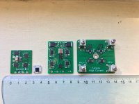
Saligny Standard - operate at max 60Hz starting from 6Vac to 51Vac. It is able to continuous deliver over 16A with 1,4W dissipated power.

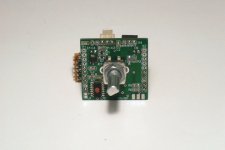
Saligny LC - Low Current. This is a very small footprint ideal bridge 10x10mm. It will operate at 60Hz between 6Vac and 40Vac. At max 5A will dissipate 0.9W

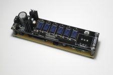
Saligny HVHF - High Voltage High Frequency.
This is the bridge to RULE THEM ALL.
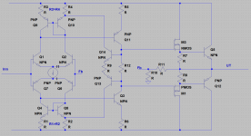
It was designed around 4 high current high frequency mosfet drivers.
Selecting properly mosfet transistors is able to work from 24Vac up to 600Vac. That mean will withstand 850Vdc at output.
As it is, will work at max 100Hz and up to 300Vac.
For higher frequency and voltage operation, there is need for external power supply - min10vdc - max 18Vdc.
So, if you intend to use this bridge at the output of your SMPS, than I recommend you to power Saligny HVHF from a separate 15V. 1Ampere will be more than OK for 100KHz. However, for higher frequency, adjacent power supply current need to be increased up to 4A for 500KHz, this will mainly depend on mosfet's used. It will support centre tap transformers.

Saligny HC - High Current. This is a beast. Using top performance, under miliohm Rdson transistors, it will be able to withstand 100A continuous with 8W power dissipation. Operation between 1Vac and 30Vac. It will support centre tap transformers.

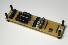
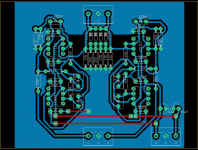
Saligny DIY full KIT - I have added one more column for Saligny DIY full kit. This include all parts to mount a THT ideal bridge, based on LT4320. This is an open source project, gerbers and source files have been already posted. Price will be 35 euro.


You may subscribe here Saligny - Ideal bridge GB - march 2020- - Google Sheets
Prices are listed on spreadsheet.
The list will be closed at end of June. Invoices will be issued via paypal. VAT 19% will be added for EU.

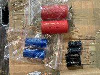
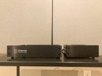
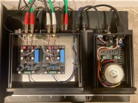
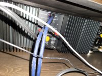
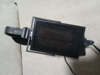
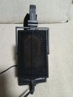
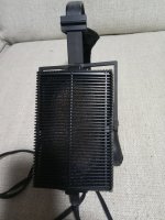
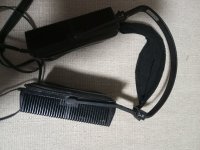
In attached picture, from left to right, Standard, LC, HVHF, HC.

Regards,
Tibi

Attachments

  • Saligny.jpg
    Saligny.jpg
    277.8 KB · Views: 1,501

Choke input filter for Aleph 30?

I’m about to have a go at building an Aleph 30 clone, courtesy of rhthatcher’s excellent boards and group buy. For the power supply, the PSU board has a nice layout for a CRC filter. So I’ve begun thinking about other parts, not least a suitable transformer, which, as in the ‘standard’ First Watt PSU, should have 18V secondaries or thereabouts, to give rails around 24 - 25 volts.

The thing is, I have several chunky toroids sitting in a cupboard here. So I started wondering whether I could use one (or more) of them. The only problem is there are none with the correct secondary voltage – the lowest I have is 25v.

So, it occurred to me, how about a choke input filter? Maybe with a choke input, one of the transformers I have would yield the right sort of rail voltage. And if I don’t need to buy a transformer, I could spend the money on chokes instead, and make an LCRC filter or even LCLC.

So, I’ve been reading up on choke input filters, and playing with PSUD2. It’s been very educational! There are Hammond chokes that could work, even as little as 10mH, but preferably 20 or 30 mH. There are downsides, though. (Aren’t there always?) One is low frequency ringing. PSUD2 shows that it is quite easily generated, getting more pronounced as the choke gets bigger or the DCR gets lower.

I discovered another problem, though - the ease with which the circuit hits the rectifiers with huge voltage pulses if the load current isn’t quite big enough. According to PSUD2, 900 volts or so can easily be generated if the load isn't sufficient.

A bit of reading on the forum here uncovered some discussion of the issue, and a suggested solution - a suitable film cap (around 0.5uF probably) connected across the input of the choke. Modelling it in PSUD2 (as C1) demonstrates that it ought to work. It also seems to reduce the low frequency ringing.

But the plot thickens at this point. Because at first I entered this cap as 0.5 uF with an ESR of 100 milliohms – a figure plucked out the air. But then I wondered if that was anywhere near correct. Film cap data sheets don’t make it easy, because the ones I’ve been looking at give ESR (or dissipation factor) numbers only for higher frequencies – 1kHz minimum, or maybe 100kHz. And when I guestimate and work out the numbers, they’re much higher than I expected. For example, the Panasonic ECQ-UA caps have among the lowest dissipation factor figures I’ve found, for this size of cap: 0.1% at 1kHz. I’m assuming you can halve that if you’re reducing the frequency by a factor of 10. But even so, when you crunch the numbers, it appears that an 0.56uF cap will have an ESR of 1.42 ohms at 100 Hz.

And that’s where things get really interesting. Because when I put those numbers into PSUD2 and re-click the ‘simulate’ button, something unexpected happens - the rail voltage drops significantly. (Also the low frequency ringing is almost completely gone.)

If PSUD2 is to be believed, a transformer with 35v secondaries would give a rail voltage not of 31v or so (as it would otherwise be), but around 25v. Which is fine for a Aleph 30.

Now, I happen to have two nice 300VA transformers with 35v secondaries. Would using one (or both) be a decent plan? Or is this a bad idea? I’m very aware that there may be things I’m missing or have got badly wrong, and these may be painfully obvious to those with more knowledge/experience than me. If so, let me down gently please!

New DHT heater, any need for a 10A+ version?

Good afternoon,


I have a working prototype of a regulator for DHT tubes. This is a voltage controled current source, so it is in no way in the audio path, similar to the tentlabs and coleman modules.


The tenative specs are as follows:

Minimum input voltage : 9VDC
Maximum input voltage : 30VDC
Output adjust range: 5.0-30V by means of a 25t pot.
Rated current : 1-10A
Peak current during warmup : 20A
Noise at Rated output current : Less than 1mV measured using a HP benchmeter.

Dropout voltage: About 3V at rated current.


Output devices: Two TO247 mosfets rated for 350W DC duty with an infinite heatsink. In reality these can dissipate about 40-50W on a heatsink under 1K/W.


I am now thinking about a redesign of my prototype to include some different features, and order a 70uM PCB instead of the standard 35uM, and perhaps even include pressfit screw connectors for the PCB.


I know its a small number of Diyers working with tubes that use THIS much curret. However how sensible would a DC regulator for tubes like the 833 Be? And is there anyone interested in the project?


I dont build with anything like these tubes, ive shipped some boards to some friends for use with some transmitter tubes. And to put it blunt further development needs to make good on my time.


A picture of a prototype board is attached. You are to use the board to mark out the holes on the heatsink, and then break of the part above the FETS.

Attachments

  • photo_2020-05-05_14-31-48.jpg
    photo_2020-05-05_14-31-48.jpg
    211 KB · Views: 628

Bass reflex standmounts 10.3 / 10P

I did these some time ago, but they were buried in a couple of large threads; seemed sensible to put them into a dedicated place where they're more easily accessible. Two modest sized standmounts for the Alpair 10.3 & Alpair 10P. Volume & cabinet dimensions are identical for both, as is damping. Only change is to vent length to alter tuning as appropriate for each unit. Quite straightforward, nothing fancy. Lightly damped alignment so they're a better match to room gain and / or high output impedance amplification. If you want to add bracing, do whatever floats your boat (don't ask, I'll simply repeat this sentence). Damping should be acoustic fiberglass, ultratouch, natural fibre carpet underlay of xyz type, Monacor MDM-2 or MDM-3 or similar lining all internal walls; I'd suggest avoiding foam however (ditto).

Please note: these designs are my property and supplied for DIY use only. Any other purpose, please contact me.

http://wodendesign.com/downloads/simpleReflex-103-10p-plan-100214.pdf

Attachments

  • Displacement 10.3.gif
    Displacement 10.3.gif
    23 KB · Views: 1,510
  • Impedance 10.3.gif
    Impedance 10.3.gif
    28.1 KB · Views: 1,499
  • Vb response 10.3.gif
    Vb response 10.3.gif
    33.1 KB · Views: 1,501
  • Vent velocity 10.3.gif
    Vent velocity 10.3.gif
    22.8 KB · Views: 1,489
  • Excursion 10P.gif
    Excursion 10P.gif
    21.8 KB · Views: 1,412
  • Impedance 10P.gif
    Impedance 10P.gif
    28.1 KB · Views: 294
  • Vb response 10P.gif
    Vb response 10P.gif
    33 KB · Views: 375
  • Vent velocity 10P.gif
    Vent velocity 10P.gif
    22.8 KB · Views: 380

Hypex fusion FA503

Hi ,
I would like to sell 3way hypex active plate amp
FA503 .
2x 500w 4 ohm 1x100w
These are unuse ,I have only 1pcs.
currenly factory price is € 630 and no stock
I would like to sell US$ 500 plus shipping.
free harness for nc502 (Ghent audio )u can use two stero power amp too.
Best regards

Attachments

  • D871D48A-C387-4490-A3B1-10BE2B0B90D1.png
    D871D48A-C387-4490-A3B1-10BE2B0B90D1.png
    160.6 KB · Views: 148
  • 7CE8BC48-14C6-413D-84BA-80B19D08D353.jpeg
    7CE8BC48-14C6-413D-84BA-80B19D08D353.jpeg
    384.9 KB · Views: 190
  • 2705B4B5-903B-4B9B-8C68-857B55641D30.jpeg
    2705B4B5-903B-4B9B-8C68-857B55641D30.jpeg
    387.1 KB · Views: 174
  • 037FBBBF-984B-4889-BFE6-3225BFA832C9.jpeg
    037FBBBF-984B-4889-BFE6-3225BFA832C9.jpeg
    516.1 KB · Views: 195

Stradivarius Violin

I purchased this cool looking violin at a second hand. I might of over paid for it , $155.00, or might not have. Because ultimately I like it. I can not play a violin yet.

I don't know much about them either. I am hoping someone can help with a curiosity or two. If it was not home made, that's a possible DIY from the east. They make a fair bit of guitars and violins and cello's out in eastern Canada. Its modelled after the Stativarious. Its missing the bridge, and obviously needs new strings. Could use a cleaning, with some kind of rosin loosening agent in it.

After that, Is it advisable to use paste polishing wax on the outer body area only*?

It struck me in the right kind of emo moment then I wanted to have it that's all I know. And that its held together through a lot of time. The case shows age in the use wear, and the way its designed says old.. Its curious where its from and its age, and whatever else might be of interest.

I was not able to find any names yet, inside or out. The bow, its there, without hair, the bow is hairless and will need some.

I'll include the main body with more detail.

If its not worth crazy dollars I am ok with that. That had no bearing on my decision to buy it. Although lots and lots of money does seem nice.

Attachments

  • 20220408_125443.jpg
    20220408_125443.jpg
    405.9 KB · Views: 149
  • 20220408_125505.jpg
    20220408_125505.jpg
    427 KB · Views: 142
  • 20220408_125452.jpg
    20220408_125452.jpg
    373.7 KB · Views: 138
  • 20220408_125539.jpg
    20220408_125539.jpg
    415.8 KB · Views: 138
  • 20220408_125620.jpg
    20220408_125620.jpg
    351.7 KB · Views: 140

SSE static noise without cheater plug

I have just finished building an SSE.

The amp sounds great, but i have some issue with static noise.

If no RCA is connected to the amp, it is quiet, no noise.

If I connect a mini jack to RCA cable, from my Macbook Pro to the amplifier, I can hear a fairly loud static noise.

The Macbook Pro has also an external screen plugged into it

I used to have the same issue with static with my Bottlehead Crack amplifier. If the amplifier was connected via RCA to the iPhone, it was quiet. If it was connected to the Macbook Pro (with external screen), I would hear static noise.

I tried different RCA cables, from the cheapo to homemade Canare shielded wire, they all produce noise when connected to the Macbook Pro.

I have tried plugging the SSE via a cheater plug. The static noise disappear.

What is causing this noise?

I am using as power transformer a Baldwin removed from an organ.

It has high voltage center tap, but it does not have 5v filament nor 6.3v filament center tap.

The AC prog has the green ground wire connected to one bolt of the power transformer. All other ground wires from the speaker jacks and RCA jacks (just one of the two) are also connected to the same lug screwed onto one bolt of the power transformer.

I would also add the amp makes a popping noise into the speakers when i turned off. Not sure if it is related somehow.

Thank you. Apart from this the amps sounds great!

MarkAudio CHR-70v3 (4" Fullrange) + TQWT

This TQWT can be made for two box in the Japanese standard size (12mm saburoku-plywood, 900mm*1800mm).
It is a reasonably priced speaker with necessary and sufficient low range and natural mid-high range.

Login to view embedded media

Attachments

  • DDVP-10-ML-07.jpg
    DDVP-10-ML-07.jpg
    300.7 KB · Views: 492
  • DDVP-10-ML-01.jpg
    DDVP-10-ML-01.jpg
    264.8 KB · Views: 525
  • DDVP-10-ML-02.jpg
    DDVP-10-ML-02.jpg
    184.3 KB · Views: 527
  • DDVP-10-ML-03.jpg
    DDVP-10-ML-03.jpg
    112.6 KB · Views: 523
  • DDVP-10-ML-04.jpg
    DDVP-10-ML-04.jpg
    41.3 KB · Views: 607
  • DDVP-10-ML-10.jpg
    DDVP-10-ML-10.jpg
    133.8 KB · Views: 697
  • DDVP-10-ML-11.jpg
    DDVP-10-ML-11.jpg
    110.1 KB · Views: 657

Optional choke placement with a choke input filter

Hi,

from a scrapped Hammond S6 organ I have the power transformer. This is a rather heavy beast, it's plate secondary voltage is 290-0-290 Vac. Due to the big number of tubes in the S6, the heater winding is capable of 6.3 V/10 A. I'm about to use the transfo in a stereo power amplifier with two 807's per channel in PP with the output trannies of two Hammond K-100 organs (plate to plate impedance is 9.000 ohms). The PSU will consist of a silicon diode bridge, so the plate and screen voltages (the latter taken from the CT) would be 800 and 400 Vdc. Too much for 807's. So I'm thinking of choke input filters. But instead of the usual arrangement of the choke's placement between the rectifier output and the 1st filter cap, I'd prefer to put chokes between the transformer and the bridge. This would have the advantages of lacking DC current bias and regulation of both DC voltages. In addition, the laminations wouldn't need no air gap, hence inductance would be increased or less turns count were possible. Even a bifilarly wound dual choke for both AC lines is well within imagination.

My question is: Does this make sense? Or does a choke input rely on the choke's DC bias?

Best regards!

New member, starting sub design.

Hi there,

I'm interested in understanding some of the fundamentals of loudspeaker design. I thought the best way to understand would be to start on a design and see what problems I encounter and what areas I need to do a bit more research in. I have a little bit of familiarity with the mathematics of acoustics as well as T&S parameters and other fundamentals of speaker design. I'm particularly interesting in horn design, having been reading about the paradise garage and the 'Levan horn' that was used as a sub in that club. I'd like to design and simulate a club subwoofer. I was wondering if there were any recommendations for steps in the design process or walkthrough type guides, as well as software for simulating the design?

Thanks

BD139 transistor board silkscreen minus E-C-B markings

Can't figure out orientation of transistor BD139 to silkscreened board without E-C-B markings with only a trapezoid marking?? Can someone tell me which way to orient the transistor to solder? See attachment. Let me know if narrow part of silkscreen is front or back of transistor . I think I have E-C-B correctly marked. There is metal on rear of transistor.

Attachments

  • BD139 board-transistor insertion drawing.jpg
    BD139 board-transistor insertion drawing.jpg
    27.3 KB · Views: 123

For Sale RJM Emerald MM/MC phono stage

Excellent phono stage with switchable MM/MC
Input impedance: MC - 100ohm, MM - 47K
Gain: MC - 57dB , MM - 37dB

Top quality parts -- Nichicon KZ, Wima caps. KOA resistors
Front Panel Express, CNC milled panels
External PSU with high quality, extremely quiet Hammond toroidal transformer and discrete rectifier diodes

Cost me around $440 to build
Asking $400+$20 flat rate shipping in US

Reason for sale: I'm also building the Salas Ultra FSP and Pete Millett LR Phono, don't have a use for all 3

Attachments

  • 2022-03-04 12.59.32.jpg
    2022-03-04 12.59.32.jpg
    263.1 KB · Views: 292
  • 2022-03-04 13.00.00.jpg
    2022-03-04 13.00.00.jpg
    261.3 KB · Views: 287
  • 2022-03-05 15.17.20.jpg
    2022-03-05 15.17.20.jpg
    361.1 KB · Views: 308
  • Like
Reactions: ranshdow

margan : non switching class B

http://www-f9.ijs.si/~margan/Articles/Class_B_Dist.pdf

Hi,

Anyone know anything about :

References
1. E. Margan, Add-on current dumping,
Electronics & Wireless World, 1985, October,
p.40.

Referred to in the above article ?
is it really non switching class B ?
Is there a good explanation of it anywhere ? (I cannot find any info).

How does S2 in figure 2 work ?
it looks like it will blow the amplifier up ........

🙂/sreten.

Can I measure resistors in circuit?

Hi

Some resistors in my tube amplifier are mounted with the numbers looking toward the PCB, so I can't read them. I did measure them already but not sure if the results are correct because I did it while they are in the circuit.

Do I need to desolder the resistor on one end or can I measure them in circuit with a digital multimeter?

I did some googling and I am getting contradictory answers.

thanks a lot

New idea for low dissipation Class A amplifier.

A new idea for lower dissipation Class A... now all the usual arguments sliding bias etc are not Class A... that's been flogged to death and Class A to my way of thinking means the "old" definition, that the output devices remain in conduction for the full cycle.

So a different approach. What if you mostly listen at lowish volume, but want the full Class A performance at high levels for serious listening. In that case the volume control setting has determined the max power that can be output to the load. Put simply, apply say 2 volts RMS from a CD player (max possible output) and the max output of the whole system has been defined. If the bias could be set to match, then the amp would always be in Class A at that volume setting no matter what the music did.
Turn the volume up and the bias is low, Class AB, so some way of doing that automatically would have to be devised.

Two approaches came to mind... the electrically easy one, have another gang on the volume control to vary the bias as the volume is altered.

That's messy.

Another idea. We all love our remote volume controls (I couldn't live without one now anyway) so lets say you have a high quality motorised Alps pot and all.

Idea... the motor signal when it appears enables an oscillator (say 50 khz... way above audio anyway) that injects a low level sine of this frequency into the audio before the volume control. That signal is monitored at the output of the amp. Lets set the levels say that volume on full gives 3 or 4 volts output, so no tweeter damage etc.
That signal is picked off wih a filter and rectified and a peak value derived that then is used to set the bias on the amp.
Result, an amp whose bias is always correct for Class A but that doesn't generate excess power loss at low levels. Interfacing say a 0 to 10 volt DC voltage to a corresponding bias current would be a challenge... perhaps opto isolators could be used.

You could even apply the same idea to a manual non motorised pot and just have a push button to enable the osc and inject the HF signal manually on demand to set the value that way.

So there we are, just one of those ideas we all get from time to time.

Remember you read it here first 🙂

Seiko PHX-50CD turns the cd, in reverse motion🤯

Hi all. Please help.
I've got a really rare and old cd player, a Seiko PHX-50CD
20220416_222608.jpg

16501410984966993428909293640333.jpg

It powers on, looks for the CD and it spins anti clock wise. Obviosly, at this point, its powers off.
I am really lost. I dont know what makes this type of problem.
Reading a lot of CD theory, I have not found anything about CDS spining reverse.
So, please, one of the masters in this forum, Would be so kind to give me some advice, or start point to fix this little gem?
Thanks in advance, and all the Best from Spain.
Alberto.

THERMAL COMPENSATION OF Vbe MULTIPLIER

A subject that causes to me questions also is the Vbe multiplier. This except the idle current that offers to output transistors, it ensures also thermal compensation to keep the bias in a safe margin unless the output devices will be in danger of destruction due to overheating. Those from you who have read the D.Self book, you have seen that he puts in this place the MJE340. From my experiments I have realised that MJE 340 is a lot slow in the recovery of the preset idle current after the pause of amplification procedure during that the heatsink it is heated significantly. I have tried other devices of common type such as BD137 and BD139 and I have realized that these are by far much faster from MJE340 in thermal compensation and thus in the recovery of the original idle current after heating. Concretely, I realized that as much higher the Vce of transistor as much slower its thermal reaction. In an amplifier with a supply of +/-70Vdc (thus 140Vpp) the peak of signal across the C-E contacts of transistor it touches many times upon the 140Vpp. Thus the use of lower Vce transistors such as BD137 (60V) or BD139 (80V) it is a risk. From the other hand I fear the use of MJE340 (Vce=300V) because his slowness (a thermal runaway watch for in output transistors? I am not sure)
Also and this time I wait for your answers with your thoughts, your experience and your opinion on this subject.
Thanks in advance for your help
Fotios

1.8 mm blue LEDs free to a good home

The mounting hole in the DIYAudio store B1 Korg chassis fits a 2mm LED, but choices for this size are limited at the usual North American supply houses. I found diffuse blue LEDs with a 1.8mm lens on a 3mm rectangular body that fits, but with a 100 piece minimum purchase. They weren’t expensive, and now I have 99 extras. I could make a super bright ugly sweater with them, but I’d rather see them in Pass amps, so I’m giving them away.

Here’s the deal: I will mail a few LEDs to US members who PM me their request and address free of charge. They will be taped to cardstock and sent with a first class stamp, so no guarantees against an occasional LED pulverization along the way. But hey, free LEDs.

Specs: Blue diffused LED, 468 nm dominant wavelength, 200 mcd intensity at 20mA, 3.0 mV typical forward voltage, 3.4 mV maximum forward voltage.

Attachments

  • 4A64E45D-375E-4974-9794-401BA6510ADD.jpeg
    4A64E45D-375E-4974-9794-401BA6510ADD.jpeg
    608.8 KB · Views: 128
  • 349BB2C2-05C8-45F5-9630-B7F522183861.jpeg
    349BB2C2-05C8-45F5-9630-B7F522183861.jpeg
    312.5 KB · Views: 132
  • A6807A7D-BD1F-4548-9BEE-3BD5E02481E4.jpeg
    A6807A7D-BD1F-4548-9BEE-3BD5E02481E4.jpeg
    489.8 KB · Views: 137

On Vbe multipliers

Hi,

I'd like to know the important parameters to choose the active device of a Vbe multiplier, aka bias spreader. Most important thing seems to be ease of mounting it in very close thearmal contact to the output devices of a power amp. So we nowadays choose SOT32/TO126 devices, as they have become rather cheap. Formerly TO92 transistors, plugged into a 5 mm hole by using thermal glue, were more common.
Next would be the collector current rating, which has to exceed the current through the Vas or predriver stage.
Transition frequency, Vce and Ptot don't seem to matter at all, as the spreader uses to be in parallel with a large capacitor and bias voltage commonly is some volts only (and collector current in the range of some few mA's).
But what about hfe? Can I, e.g., use those ancient video transistors with their rather modest hfe, such as BF457, that I have laying around in large quantities?

Best regards!

GFA-555 question

Hi All. I have a GFA-555 (I believe a MK1 from my research) that is still working but has some issues. I'm a Controls and Automation Engineer, but I have zero experience working with amplifiers. This amp has tremendous sentimental value to me (my deceased Brother and I used to listen together with this amp) , and I'm not sure I trust myself to try and repair on my own. The amp is making the 'mouse fart noise' when it powers down, and I've lost a tweeter in one of my mains (Polk rti12). I'm not sure if the two are related, but I've pulled the amp from service until I can restore it.

I have decent Electrical knowledge, but it's mostly around Industrial Controls (480 3PH and 24V DC). My soldering is decent as I'm big into building and flying large RC Helicopters. None of this is related to amp repair, but I wanted to give an idea of my background and basic skills. I found the Hoppe's Brain site, but I'm not sure if repairing the amp is something that is easy or difficult? Am I just swapping out boards and replacing caps, or is a full restoration super complicated? If the amp didn't have so much sentimental value, I would probably dive right in. I would feel horrible if I damaged it beyond repair.

Is this something I may have the skills to tackle, or should I play it safe and leave it to the professionals? I live in Greenville, SC. Not sure what to do here. What are your thoughts about the best way to tackle this?

Thanks in advance,
Bill

Attachments

  • Adcom 1.jpg
    Adcom 1.jpg
    388 KB · Views: 106
  • Adcom 2.jpg
    Adcom 2.jpg
    548.3 KB · Views: 111

Passive Crossover PCB Layout Question

Hello,

currently I'm in the progress of building a small 2 way desktop speaker, need help for the crossover PCB layout, my first attempt is make 2 layer with bottom layer as a ground plane but after browsing around seems like single layer are used for most of the passive crossover PCB then I try to make the single layer layout, is there any advantage using single layer for this purpose other than cost? I attached both of the layout and any suggestion, direction, critics are really appreciated.

Thank You

Attachments

  • Single Bottom.jpg
    Single Bottom.jpg
    99.1 KB · Views: 275
  • Double Bottom.jpg
    Double Bottom.jpg
    82.8 KB · Views: 271
  • Double Top.jpg
    Double Top.jpg
    93.8 KB · Views: 289

For Sale Salas I-Select and Muse volume control with display

For sell a complete kit for volume control (Muse kit as sold in here) with source select.
Probably the best the best remote voume control with display with reasonable cost.
Both remote and display are a must for me, so I didn't go for newest version (no display)
Only selling this because I have another one identical (see first picture)

I designed my old power supply board for it for two reasons:
1. I wanted almost zero length for signal cables (with Muse chip located beneath I-Select there is no signal cables going from rear to the front and then to preamp). Only cables that don't matter to sound quality are going to the front panal (see last image). They are long enough to place the volume control and display wherever you want.
2. Zero space taken by the power supplies (located beneath I-Select). They are also close to the analog / digital part of the Muse kit.

I also added a galvanic isolator for display in case is needed.

Adafruit display large display is used in order for the volume to be easily seen in day and night. (see image of the front panel of my preamp which includes the same kit)

In detail, it includes the following main parts
for I-Select
6 Panasonic TQ2 relays
Rotary selector

Muse volume control:
Two transformers
3 additional power regulators
Remote (calibrated)
Cables

For Display
Adafruit big led display
ADUM1250 galvanic isolator

Asking
185 euros (without transformers)
200 euros (with transformers)
Plus shipping. Paypal for friends
Worldwide shipping via registered trackable airmail:
11 euros (without transformers)
15.50 euros (with transformers)

Attachments

  • muse_display.JPG
    muse_display.JPG
    111.3 KB · Views: 424
  • iselect.JPG
    iselect.JPG
    105.8 KB · Views: 404
  • power.JPG
    power.JPG
    129.2 KB · Views: 413
  • control.JPG
    control.JPG
    116.2 KB · Views: 380
  • trans.JPG
    trans.JPG
    128.6 KB · Views: 373
  • remote.JPG
    remote.JPG
    140.4 KB · Views: 362
  • cable.JPG
    cable.JPG
    95.3 KB · Views: 377

Connect 1 turn table to 2 pre-phono...heavy hummmm

Hi guys, I need your suggestions:

I have a turntable with a MC capsule (Technics SL-M1, AT OC9/III) and I want to connect it to 2 pre-phonos, one tubes (EAR 834p) and other SS (Pass XP-15).

I thought that a RCA switcher (tc-7240) could do the job (turntable -> switch -> ph1 & ph2 ->prea-amp (passive) ->amps), but not, I got a heavy "hum" when I take this way. Mainly from XP-15, seams that EAR is more "tolerant".

Off course I can connect and disconnect, but I think that soon I will break something.

Any ideas?

Thank you,

JL Audio 500/1 new issue for me

I have this amp which powers up and idles at 0.8A. Good rail voltage at about 96v. I removed the output fets which measure good, jumped the opamp and output pads to check the output drive; and found good strong clear square signal on all output gates.

I put the FETs backing the amp. Cleaned all switches and controls. I still cannot figure out why only half the waveform is on all speaker terminals as pictured. Amplitude changes with drive signal, and frequency input shifts the waveform indicating half the signal is going completely through the amp.

Why is this amp only outputting top waveform?

Attachments

  • 77EC4354-D8EE-47BB-AFD6-3627F063CB30.jpeg
    77EC4354-D8EE-47BB-AFD6-3627F063CB30.jpeg
    427.2 KB · Views: 92

Need help identifying this tube amp

My buddy bought this amp online from a guy on the east coast. From all the google searching and forum searching I have done. I have found that a Chinese company made integrated amps like mine. One of these amp was called the bewitched 6550 you can see at this link. http://lampizator.eu/amplifiers/china/bewitch 6550/bewitch.html and TrueHarmonix 6550 as reviewed here. https://6moons.com/audioreviews/trueharmonix2/6550.html.


Mine is not an integrated amp. Had a flat silver faceplate that I took off because it was bent. You can see two of the inputs on mine are covered with black tape. I am wondering if some other company made amps only off of the integrated platform? Could i turn mine into an integrated one? The guy my buddy bought it from said he got it from a very small company that made custom amps. trying to find any information i can.

Thanks
20220414_191243.jpg
20220414_191251.jpg
20220414_191258.jpg
20220414_191315.jpg
20220414_191328.jpg

Looking for tweeter: dynamic sound, good tone.

I am building monitors with the Vifa ne123 4" as mids. I like this vifa.

I am looking for a tweeter that is going to have dynamic, impactful sound and a nice rich tone. Something between the sound of a compression horn tweeter and a large soft dome and still bearable for long term listening.

I tried the vifa ne19vts 3/4" soft dome. Garbage sound that is like dragging a stick across a cyclone fence. Tizzy soft and zero tone. This is the opposite of what I want.

Tried Morel CAT 378. Better but I'd want a bit more impact, and it's still slightly tizzy.

Any recommendations? Hard domes that are not harsh?

appreciate your help.
Herman

Adding a display to Rpi help

After seeing the inspirational Falk thread https://www.diyaudio.com/forums/pc-based/371976-falk-dp-01-a.html I fancied trying a display on my Ian Canada Rpi streamer.

I bought one of these as it was at the cheaper end of the scale for a starters.

£15.86 9%OFF | 4 inch LCD HDMI Touch Screen Display TFT LCD Panel Module 800*480 for Banana Pi Raspberry Pi 2 Raspberry Pi 3 Model B / B+
4 inch LCD HDMI Touch Screen Display TFT LCD Panel Module 800*480 for Banana Pi Raspberry Pi 2 Raspberry Pi 3 Model B / B+|LCD Modules| - AliExpress

I don't want the touch functionality, just to display what Moode or Volumio would show.

I powered up with 5v and it showed a 'no signal' screen so a decent start. I tried connecting to my Sky TV box to test . The picture was there but massively garbled. Maybe a resolution incompatibility. The Sky box is probably at 1920.

So I then tried plugging it into the HDMI of the Rpi. Made sure the port is active in Moode. This time just a black screen that seemed to go on and off between the blue 'no signal screen.

Any ideas. ? I maybe foolishly thought this would be plug and play!

3 gain equalizer hearing aid simulation fact

Dear All,

Let me introduce one of my project what I worked through 12 years back with a professor.
Still it need to be more efficient one.

Its a low cost hearing aid amplifier using LM324 as a main Op-amp.

We were trying to apply 3 frequency selecting gain circuits, 1. Bass Control 2. Mid frequency 3. Treble control.
I did apply some model from online for having suitable gain at human sensor range like 2-3KHz.


HA1.PNG


It looks clear, I have been trying

1. Treble and Bass control by frequency selecting gain, considering High, low and mid frequency gain through frequency selector.
2. Tried to boost and buck the gain of the amplifier.
3. Assume all OPAMPS are 741.
4. In mid frequency band the gain should be 17dB to -15dB. According to this design, as audio signal is fed by single input, so all frequency signal from the air will be chosen by selector, must be flat for minimum frequency gain.
5. As far as I remember, 200Hz to 8kHz, we have used signal generator.
6. My tone controls have parts to boost the frequencies and other parts to cut the frequencies. Are there any people with hearing problems that need frequencies cut because their hearing is "too sensitive" to those frequencies?


Take a look in the bode plot here,
HA2.PNG


Not sure the system works properly.
Suggest for meaningful simulation.

Miller & Kreisel KX10BK Subwoofer

Hello to all,

recentrly I bought a defective Miller & Kreisel KX10BK Subwoofer, sincerely I hoped it was simplier to repair. I see a couple of transistor burned, but it seems thay aren't in the amplification path, more in the signal-sensing circuit to automate power on.

Anyway, I think it's quite easy to repair with a service manual, but I can't manage to find anything on internet. Can someone help me?

thank you

Stax SR_Lambda Normal Bias and Or Modified Stax SRM T1 amplifier Normal and Pro Bias Energizing Unit 8.5/10

Here is my trusty modified Stax SRM T1 according to the "'JImL" (James Linn) Cascoded Current Source Stax SRM T-1.

Also up for sale are two Stax SR Lambda Headphones. Both are perfectly balanced and are flawless .. as are pictured

Very rare, Perfect mineral Wools and foam driver dampening coverings. No plastic damage.
s
ame day shipping and I'll eat half of the PayPal fee.

Thanks a whole bouquet, for interest in famous pristine 40 year old headphones with Modified energizing amplifier for up to three pairs of headphone.'

640 for stock SRM T-1 with GE or JJ Electronic tubes, modifications, and correct biasing.
865 for modified T1.

for Stax SR Lambda Normal bias phones in pristine conditions. Perfect channel balance, all original --- these headpads are perfect too.
500.

These are commonly found and sold on ebay but finding a perfect and or even JUST an ACTUALLY balanced -- channel balanced pair of 40 year headphones seems to be a steep challenge itself,
..


-Contact information optional and provided,
-each item will be triple bubbled, and triple-boxed.

RCA to 3.5mm for phone devices, and power cord come with the amplifiers. Rca to rca cable included too.

Yamaha CR 2040 Class A/B receiver for sale.

Added a ton of photos and bumping the listing.

Stax L 300 headphones for sale: Sold.

Stax SR 009S for sale ... Please inquire.

Attachments

  • IMG_20220228_102733.jpg
    IMG_20220228_102733.jpg
    280.8 KB · Views: 165
  • IMG_20220405_024746.jpg
    IMG_20220405_024746.jpg
    367.5 KB · Views: 127
  • IMG_20220405_024705.jpg
    IMG_20220405_024705.jpg
    492.2 KB · Views: 142
  • IMG_20220405_024658.jpg
    IMG_20220405_024658.jpg
    515.4 KB · Views: 143
  • IMG_20220405_024721.jpg
    IMG_20220405_024721.jpg
    380.6 KB · Views: 160
  • IMG_20220405_024657.jpg
    IMG_20220405_024657.jpg
    438.2 KB · Views: 119
  • IMG_20220405_024723.jpg
    IMG_20220405_024723.jpg
    446.7 KB · Views: 125
  • IMG_20220405_024755.jpg
    IMG_20220405_024755.jpg
    467.4 KB · Views: 124
  • IMG_20220405_031828.jpg
    IMG_20220405_031828.jpg
    294.7 KB · Views: 115
  • IMG_20220405_031831.jpg
    IMG_20220405_031831.jpg
    280.9 KB · Views: 162
  • IMG_20220405_025509.jpg
    IMG_20220405_025509.jpg
    198.8 KB · Views: 138
  • IMG_20220413_051745.jpg
    IMG_20220413_051745.jpg
    404.5 KB · Views: 151
  • IMG_20220413_051755.jpg
    IMG_20220413_051755.jpg
    507.6 KB · Views: 119
  • IMG_20220413_051818.jpg
    IMG_20220413_051818.jpg
    530.8 KB · Views: 103
  • IMG_20220413_051841.jpg
    IMG_20220413_051841.jpg
    580.3 KB · Views: 115
  • IMG_20220413_051853.jpg
    IMG_20220413_051853.jpg
    426 KB · Views: 138
  • IMG_20220413_051848.jpg
    IMG_20220413_051848.jpg
    458.5 KB · Views: 131
  • IMG_20220413_052231.jpg
    IMG_20220413_052231.jpg
    277 KB · Views: 109
  • IMG_20220413_052224.jpg
    IMG_20220413_052224.jpg
    257.8 KB · Views: 127
  • IMG_20220413_025431.jpg
    IMG_20220413_025431.jpg
    390.5 KB · Views: 131
  • Like
Reactions: pilli

MC Head Amp hum, bad PCB design?

Recently I build this MC Head amp using an own PCB design. It sounded pretty good I think so far, except for a quite loud hum. I tried everything so far, moving the PSU out of the box (no ripple voltage btw), different grounding and so on. The noise sounds like 50 Hz hum and it's louder without the turntable connected so I believe that it must be picked up by the PCB from its surroundings, even though its in an grounded metal box.

Datasheet for LT1115 says that the grounding of PCB is indeed important, suggesting single point grounding. Looking at the PCB design I know realize that I may have created a "ground loop", or is this possible? Since I can't figure any other way than make a new PCB to decrease the hum, so what else should I change? Adding a extra layer just for ground?

Attachments

  • MC_head_board1.png
    MC_head_board1.png
    12.9 KB · Views: 234

Cold war surplus capacitors

So I was a bit sad thinking that some of the parts I have known to be good and sometimes great may no longer be available due to recent world events.
However, the popular auction site listings now all show the origin as being “Ukraine”, all of them…
Funny how just a couple weeks ago or so that they nearly all said USSR.

Well maybe the parts are still available, but I have a feeling someone is not being truthful about where they are coming from, kind of like diamonds.

The Speedsters that Too Bye Ate

Walked in a hardware store's lumber section, and while randomly walking past 12 foot kiln dried 2x8s of redwood, I saw the impossible ... the last 4 feet of one of those boards was burl. When I flipped it over, it was all the way through identical.
Thinking they may not sell it to me, I walked up to the lumber counter with it and the person told me I will just charge you for 8 ft , since that last four feet is all just trashy burl that can't be used. I only paid $22 for the entire board if I'm not mistaken. Took the four feet to a sawmill and had them slice it 3/32" thick slabs. Therefore there is a seam I tried NOT to hide. I wanted everybody to ask me why there's a visible seam down the sides, where I can tell them because it's made from a redwood 2 x 8 that could have ended up a floor joist!!!


20220409_161548.jpg
20220409_161603.jpg
20220409_161625.jpg
20220409_161918.jpg
20220409_161936.jpg
20220409_162359.jpg
20220409_160943.jpg
20220409_162135.jpg
20220409_162156.jpg
20220409_161015.jpg
20220409_162300.jpg
20220409_162240.jpg

The '22 Dell Inspiron 15 5510 is a piece of s...

I thought I'd but a nice reliable laptop to perform all my measurements etc. with. Based on success I'd had in the past with Dell (two inspirons - DJing in 2010's) I grabbed a new one with a largeish 15" screen for measurements and all things audio. Backlit keyboard was an essential requirement to me as well.

Boy was that a mistake.

This thing has been a lemon. I sent Dell my feedback but got no feed, back.

  1. I've not seen so many BIOS (mainly) and driver updates on all other machines I've had in my life combined. I get that BIOS updates are more common now, we see them a bit on the intel NUC's in the office but this is a joke, there must have been at least 20 on this thing since I got it new. I think Dell knows these things are a little, uh, unstable.
  2. The USB is seriously bad. It only has two USB A slots and 1 USB C (yes my fault for not checking) but 60% of the time I plug in a DAC, soundcard, DATS, USB Mic, it just straight up doesn't even see it in the devmgr or if it does it just says unknown device - yes this is any slot and yes I have verified with other machines that the USB devices are not at fault.
  3. To make matters even worse, Dell insists on the use of this audio device controlling software MAXXaudiopro - which applies huge EQ to anything plugged in instantly, even headphones, and you have to open the app to disable the enhancements or manually disable enhancements via the control panel, to every device, every time it is plugged in i.e. it has no memory of your device settings. If you close or uninstall MAXXaudiopro, the headphone jack doesn't even work at all!
  4. Its not just me that this would **** off - surely people using this laptop for studio or production work would be just as pissed as I.
Believe me I've tried everything so I'm not going to bother trying to fix it I'm just going to try and return it.


TL;DR - The latest Dell inspiron has left me steaming mad - as laptops are a tool we use, please give me your recommendation for the best laptop (preferable the most stable) for the audio work we do?

A useful reference publication of electronics symbols from CIE

I happened upon this excellent reference while searching for a very, very, very simple CAD program (which continues to elude me).
I would appreciate your suggestions if you know of one.
I run Linux Mint Mate 64 bit, so something that works in a recent Ubuntu distro might be OK. M$ Windows apps need not apply.
Thanks...
Here is the electronic symbols publication URL:

https://www.cie-wc.edu/Electronics_Symbols_Handbook_CIE.pdf
Later, DAAB

A Buffer for Class AB Amplifiers

As I have been saying on many threads, I am only interested in Class B amplifiers.

However, people in this forum as well as everywhere consider Class B amplifiers a crime against audio, because of their crossover delay and non linearity.

Although these can be tackled to an extend, people prefer to use extra circuitry to convert Class B amplifiers into Class AB.

Thus, I have decided to make a circuit without resistors on the path of the base currents of the output transistors, something, which I have decided to call " Enigma Machine ".

I think, I have been able to make and test the said circuit, a schematics of which is at the addendum of this document, just after the explanation of the said circuit.

Here is the document :

A Buffer for Class AB Amplifiers - Google Drive

Amplifier

I am incredibly proud to announce I have made an amplifier with a schematics I have dreamt for a long while. I have only done very preliminary tests which are excellent. I have not yet written up the document, but, I am impatient to provide this information.

At present, the document contains the schematics only and will be updated, hopefully, soon.
Here is the link : Amplifier - Google Drive

Please, note : there are a lot of N. E. ( Not Equipped ) components. The reason to be on the schematics will be explained.

DIY project (Ekta 2D + Visaton La Belle combo)

Dear all,

Just wanted to share my DIY full range active speaker project which is a combination of the Ekta 2D design of Troels Gravesen (tweeter + mid) and the Visaton La Belle ( 2 x 8inch woofers) where the Hypex Fusion FA122 of the Ekta 2D is replaced by the 3 channel FA253 Fusion amp.
Cross-over between tweeter and mid is designed by Troels Gravesen (with first order, second order and 4th order LR options, all in the range between 2-2.5kHz), and LR2 cross-over between mid and bass at 300Hz (same as original Visaton La Belle):

Image 005.png

Image 006.png


Below the frequency response I measured with Umik-1 and REW software. Is a combination of far field measurement (same as Troels at +- 70cm distance from the speaker with microphone height between tweeter and mid) and a near field measurement of the woofers (corrected for baffle step loss), where in REW I selected the psycho-acoustic smoothing option:

Reponse psycho acoustic.png


In the end - after hours and hours listening and finetuning the hypex parameters - I am now very happy with the results! ;-)

Regards,
Wouter

Suitability Of Copper Clad Aluminum Enameled Wire for Magnepan T-1D Rewire

Any chance 10% Copper Clad Aluminum Enameled magnet wire would perform significantly better in long-term corrosion resistant durability & extended continuity lifespan ? .....As I've never seen any examples of long term solid copper enameled mag wire corrosion or pit opens, would 10% Copper Clad Aluminum magnet wire exhibit significantly Longer corrosion free Lifespan & Reduced pit--open continuity failures long-term performance ??


Jmj

Why bootstrap?

When I read this thread I wonder about one issue.

Hugh, and Rod are two persons here which are keen on using bootstrap for driving the output transistors.

I wonder what are the pros and cons?

Pros: More power with given design, more peak drive voltage, less parts, simplier power supply for the drive circuits.

Cons: Start-up thumps, poor bass performance(?), poor clipping characteristics(?)

Is the major reason to use bootstrap to save parts (=costs)?

Are there any sonic properties involved?

Nad 2700 recapping

Hi all,
I have a question about upgrading this amp.
Where can I get power Capacitors replacements for this old amp?

Power Capacitors 2 x 10000uf – 80v
Power Capacitors 2 x 10000uf – 120v

I found this upgrade kit (which I would probably get) containing
35 Nichicon audio capacitors KZ, FG, FW, KW but power Capacitors are not included.
Any directions or general thoughts about my plan (should or should not) would be highly appreciated.
BTW, The reason for the upgrade is that It makes some dearty sound from the speakers like bad contact sound from time to time. Do you think changing the Capacitors of a 30 years old amp might solve it?

My speakers are martin logan source.


Thanks

Dual DA6001 muted?

Working on a Dual DA6001 which appears to be just muted. I get very faint audio on speaker terminals at very high input signal voltage. Customer said amp never worked straight out of the brand new box, though the amp is several years old now. It powers up, has rail and regulated voltage. All opamp outputs have audio signal on them, and there is audio going to Pin #8 of the driver board, which is using IR2113 and a new one: HCF4093.

I see a square wave on the HCF4093 at several pins including pin 8.

On the IR2113 I have the following voltages:

1. -68.9
2. -68.9
3. -57
4. 0
5. -0.027
6. 0.330
7. -0.021
8. 0
9. -57.1
10. -57.1
11. -68.2
12. -68.9
13. -68.9
14. 0

I'm not seeing any drive nor signal on output FET gates.

Polar maps for W4-1320SIF, FF85WK & FF125K

Or "Why should the fullrange gang not also post those pretty colourful graphs" 😉

I was measuring the response of drivers for a multi-way project and though I'd give my FR drivers a spin, quite literally!

These are all drivers I've had for many years:
  1. Tang Band W4-1320SIF, mounted in a 9 liters DCR
  2. Fostex FF85WK, mounted in a 3.25 liters reflex
  3. Fostex FF125WK, mounted in a 8 liters reflex
The first two are relevant as they are current production units, whereas the FF125K was measured for kicks mostly. All vents were stuffed with balled-up tissues.

I measured 0deg to 90deg in 5deg steps, which is mirrored on the polar maps. The SPL should reflect sensitivity accurately enough; I set the amplifier for 2.8V and placed the mic at 50cm, then reduced REW's output by 6dB.

First off, all three drivers on-axis, for comparison's sake:

w4_85_125.png

W4-1320SIF 0-45deg response and polar map:

w41320sif_0-45.png

w41320sif_dir_1k.png

FF85WK 0-45deg response and polar map:

ff85wk_0-45.png

ff85wk_dir_1k.png

FF125K 0-45deg response and polar map:

ff125k_0-45.png

ff125k_dir_1k.png
  • Like
Reactions: grindstone

Cast in stone speaker

The Glencairn Museum in Bryn Athen, Pa., has an unusual built-in-a-wall bass horn with a mid/treble array that must have produced a fair amount of volume in its day. Located in the "Cloisters" area, it is easily missed on the usual tour unless you check it out on your own. The museum was the home of Raymond and Mildred Pitcairn from 1939 (in construction 1929-1939) until 1979. What a blast it would be to fire it up again!

Attachments

  • IMG_0310.jpg
    IMG_0310.jpg
    729.4 KB · Views: 137
Projects by fanatics, for fanatics
Get answers and advice for everyone wanting to learn the art of audio.
Join the Community
507,680
Members
7,883,980
Messages

Filter

Forum Statistics

Threads
406,019
Messages
7,883,980
Members
507,680
Latest member
McCoy22