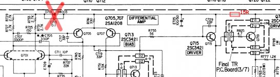

D701 conceivably does have an effect on the DC conditions and may even be part of a thermal compensation arrangement for the front end and so I would not link that out without some serious testing of the effect of doing so. Adding the 15 ohm has some merit on reducing noise on the rail, again you need to test and see the real effect and any detriment, for example under full drive conditions.
The diode helps sets the bias for those two pairs, it may not be optional (what's the drop across R741?) - the capacitor is probably needed for best performance.Hi, I'm willing to try the following modification of an old amplifier, shown with the red marks. Any suggestions? Thank you
What is the rationale for the 15 ohm resistor other than to reduce the headroom a tiny amount? I'd be slightly worried by introducing impedance between the high current output stage and the 100µF rail-cap. You'd need to check stability.
If you want to reduce ripple on the rail for the input section, add an R+C filter between driver and VAS ? The driver may take quite high peak currents and you want its rail not to droop when this happens or headroom is directly limited.