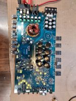
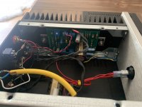
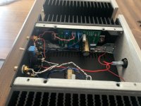
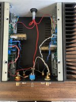
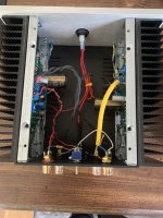
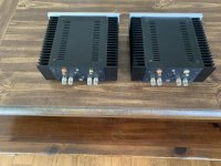
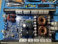
Not as familiar with MTX amps as the others.
This amp uses 75339P PS FETS. I've never seen them before.
Is it normal for these power supply mosfets to heat up so quickly?
I know it is not in the heatsink, but I have never had power supply mosfets get this hot in only a few seconds. From my experience the outputs are the ones you must pay special attention to.
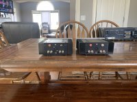
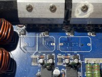
The gate resistors are 61R9 and read good.
R117 in the pic reads good but is very discolored. Would it be wise to replace it with a higher wattage?
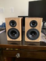
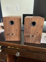
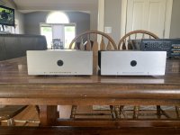
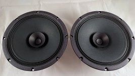
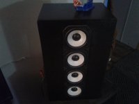
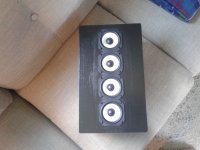
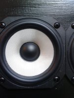
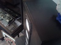
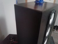
Lovely little speaker to suit a small room or use as near field monitor (been using them next to my computer)
Not made by me - purchased Sept 2021 from fellow DIYA member @Dkalsi - who did a lovely job when he made them
I have really enjoyed using them while based temporarily in DC - they have great detail and in ok level of bass. Good down low or at volume.
But we are moving on and try as I might I can't find the space in my suitcase otherwise I would take them with me.
Dayton RS125
Vifa tweeter
Walnut veneer finish with translam baltic birch baffle
9" x 6" x 8.5"
23cm x 15.5cm x 21.5cm
So Im sitting at the work bench with a few pre-amps and tone control boards.
Some have come with Knobs some have come without knobs.
Im trying to draw up what my control panel will look like. Mains power s/w. AMP selector switch, Speaker selection switch.
Im going for a steam punk look. And had this idea. Can I replace the knobs with Sliders.
So slider for volume. Smaller sliders for Low / Mid /High balance control.
I did some reading And searching.But all the sliders I found have 3 pins only.
Like for the pots you get a double gang i.e.6 pin. Do you get double gang sliders. ?
My pots are all 100K. So replacing them with 100K sliders work ?.
I could always have two sliders for each control but Na that would take up too much space.
Any help with the right part name or what its called would be helpful.
Just want a confirmation that the idea will work before I blow money buying these sliders.
I have built up new clone boards for an old non working 303 I bought recently and can only achieve 12.7 volts maximum on each board despite being able to set the regulator voltage to 67 volts as it should be.
I have checked I haven't done anything silly and cannot see anything obvious, but have duplicated the problem as it is the same on both boards!
Any suggestions?
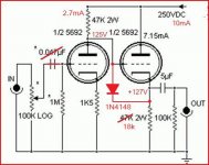
Hi all can you help me with this project, I'm just a tube noob here.
Charlies line preamp with 6N8S instead of 6sn7s.
Is it a good tube within operating specs?
Looks like max voltage is 330.
Any help from the community would be greatly appreciated
Thanks in advance...... Robert
Since, BJTs input junctions conduct an electronic current exponentially, it needs some voltage for this little current to reach levels that are encountered in amplifiers. This is usually about 0.6V to 0.7V. However, this little voltage causes crossover problems if it is not addressed. The latter function, is usually done by VBE multipliers. This thread is intended for users to post those VBE multiplier topologies and even actual circuits which they found to perform best.
I am still hesitant about changing the VBE multiplier circuitry of my amplifier. It seems, it is impossible to implement a VBE multiplier or equivalent with a sharp step characteristic and with full temperature compensation. There are various variables involved often requiring approximations to the level of regulation needed.
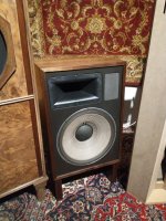
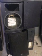
I bought a used pair of the JBLs for this kit and, while they sound good, they look terrible. Kind of a rat-like color that does not impress SWMBO. I'm looking for suggestions to make them look darker and less rat-like. I've heard one guy suggests using MinWax wood hardener for this purpose, and to make them last longer. I've also seen people who have used hair spray, diluted varnish, contact cement, all sorts of stuff.
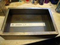
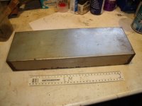
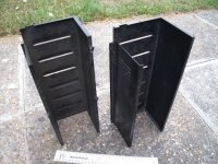
1) Chassis for a project (valve amp or radio). This is a folded and welded bare steel chassis, professionally made. Dimensions are (+/- a couple of millimetres): 386 x 260 x 93 mm with a 21 mm lip on the bottom 1.4 mm thick steel. Heavy. Not drilled or punched. Minor rust marks in places. With base plate. £15 collected.
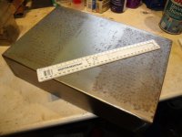
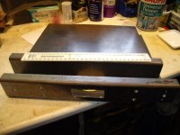
2) Chassis for a project (valve amp or radio). This is a folded and welded steel chassis, professionally made. Dimensions are (+/- a couple of millimetres): 410 x 138 x 62 mm, I forgot to measure the lip, ask if this is important, 1.5mm steel. Heavy. Not drilled or punched. Minor rust marks in places. £10 collected.
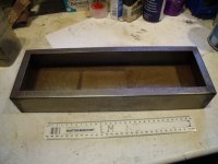
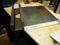
3) Two half chassis. Folded steel “J” shaped to form up to a square tube (no end panels) 340 x 380 x x57 mm. One has a 75 mm diameter hole in the middle 70 mm from the long face and some cuouts in the "front" face (see photo 6). 3.25 mm thick steel! Heavy. Minor rust marks in places. £10 Collected.
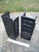
4) Two steel covers. These are “U” shaped with stiffeners/flange and louvres. I forgot to measure these but about 4” x 4” x 12” (I’ll measure if any interest). Heavy. Some small holes near edges. One is black crackle finish and the other black matt, £10 collected the pair.
Any and all can be collected from Battle near Hastings in 1066 country most days or early evening. They are quite heavy so will absorb a lot of vibration.
I can deliver in the Eastbourne/ Hastings area for petrol costs. E&OE.
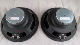
As a matter in interest only, how far up the range could this woofer be taken?
Usually such a transducer would not be taken much above 2-300Hz but it seems quite smooth further up.
Quotes range is up to 1.8Khz, frequency response is quite smooth up to that range. However no impulse response plots are available so there is no way of knowing how it would perform, distortion looks quite reasonable however.
Im trying to design my own chassis and am wondering what are some methods for hiding the faceplate mouting holes. If the aluminium was thick i suppose one could just thread the backside but im working with 5t thickness and thinner, preferably 3t if you could still do hidden screws there.
I just registered, after browsing some of the older content here, and just wanted to say this really looks like a great site. I look forward to meeting and getting to know some of you. I'm an EE by profession, but the bulk of my training and experience has been in digitally-related arenas. I've gotten quite interested lately in things like audio, RF, etc. I'm planning to tinker with some amateur radio work, and I also have an old circa 1938 Zenith floor standing radio that I'm going to attempt to restore. Just getting geared up now to start shaking down its power supply circuitry.
Well, I have to get real with myself and realize that life and work are just too demanding to allow me the time right now to take on my OB dream project. I have collected just about everything needed but have never found the time to cut the baffles and bring this project to conclusion. And so, with a heavy heart, I am letting the dream go for now. Maybe someday I'll pick it up again.
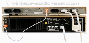
I purchased a nice working Marantz CD73 but won't be able to pick it up until this weekend.
I also purchased the RC430/RMC12 remote unit separately from another seller and just received it this morning. It powers on and everything seems to work, my question is how to hook it to the CD73?
The remote unit has what looks like plain RCA cables but coloured orange... does anyone know what cables will work? Included is a stock pic found on google
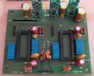
I currently have a set of power supplies and crossovers from a Martin Logan Quest that I'm wanting to find a way to properly test prior to hooking them up to anything. The amplifier hooked up to the speakers either blew up in a very had way or was exposed to some kind of power surge. The power supplies look ok other than one has a blown resistor near the bottom.
If the ESL power supply board and main transformer are still ok I should be able to save this speaker. Any help is appreciated as this whole electronics repair hobby is pretty new to me, no shops will touch this stuff so I have to do it myself.
Power supply 1 has a blown resistor inline with the speaker signal wires that turn the power supply on when you play sound.
#2 looks fine, no physical damage, but must be tested
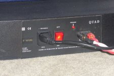
My Quad ESL989 speakers have been in my ownership for around 3 years. I originally bought them with a view to “improve” them, but on arrival, they appeared to be faultless so nothing has been done other than to change the outer “sock” which was black to a new blue sock, obtained from One Thing Audio. Other than that, they are as they were shipped by Quad. They were serviced at Quad in August 2014 and have consecutive serial numbers 901255 and 901256.
Any prospective owners should be aware that these are large speakers, but at last, they give the electrostatic design the bass which has been missing for so long from Quad ESL products. I should add that I have owned around 6 ESL 57s of various vintages and I much prefer these speakers in terms of detail, depth and power.
The sound, as you might expect, is superbly detailed, voices extremely natural, and transients just amazing. The speakers are connected to Hypex NC400 Class D amplifiers, which are totally silent and well known for their performance. Music sources are generally FLAC files from a music server.
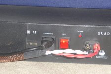
The speakers are unmarked, in original condition, all panels are working without any transient pops of clicks and the speakers are available with the original packaging from Quad
Listening is highly recommended, as is collection from our location, which is just south of Cambridge.
Hi I usually use an electronic load with nearly no functionality or to be honest, I think it have some features but the manual and the unit is almost impossible to get to do anything. 30 min of trying for 60 sec of constant current test!
I am thinking if it is possible to buy a new electronic load where I can program "sweeping" resistance, i.e. to test an amplifier from 8 to 2 Ohm or to test how a power supply react to change in load.
Is that something an electronic load normally can do?
What would you recommend, a Siglent?
Hi
i have this XMOS from Diyihnk i fire it up with 3.3V / 0.6A BUT in two laptops Windows 10 full updated on devices manager menu show me this yellow mark error ""DIYIHNK DFU""
I have try reinstall different drivers version but fail.
I have been looking at the MJE15028/30/32 and MJE15029/31/33 transistors from ON Semi. The datasheets clearly show a hfe of 150 at 25C stable up to 1A, then falling as we approach the 8A limit. This for both NPN and PNP ; actually the charts are shown side by side.
From that I would determine that I am guaranteed hfe=150 if I keep it below 1A and over 25C.
So I have bought around 3 dozen pairs of those transistors, and I measured them at home. Many I measured at 1A, others at a very small Ic (but the differences were minimal).
I discovered that the PNPs have outrageously high hfes, most were around 360 with a good bunch at 380 as well. A batch of 20 PNPs from RS turned out to be at a uniform constant of 250, which is the smallest I have measured.
The NPNs were all over the place, but consistently between 80 and 150, with only a couple at 150, most were around 100.
I spoke to Farnell about this and they have assured me these have come straight from ON Semi, no brokers in between.
I have posted a similar question before, cannot remember where, and was told not to design anything that depends on the hfe being either matched or of a specific value.
Well, I am finding all this nonsense. If the datasheet says 150, so it should be, otherwise it makes a mockery of the datasheet. At worst it should be higher than stated so that they transistors can still be driven almost as expected, but not below (by over 50% of the stated value for the NPNs and by 100%-150% over for the PNPs). The PNPs are in a world of their own, so here I am trying to match my push-pull stage with one side having hfe of 100 and the other side having a hfe of 300.
So why bother buying these transistors if they behave as badly as 50 year old BD911s ?
In my opinion something is fishy here. Why is the datasheet showing them as complementary, made for each other, like Adam and Eve, with charts shown side by side, with the SAME datasheet covering both NPN and PNP - when the truth is so far beyond all this?
I prefer connecting to laptop this way, instead of the USB to DAC. Because I refuse to switch this DAC after it took what seemed like forever to find one I want to stay with lol.
Bit of a long shot but wondering if anyone has a pair of 0.5 mH inductors suitable for use in passive xover that they would be willing to sell. Ideally in UK but EU would also work.
After almost 2 decades of being out of the loop when it comes to home audio and home theater I recently was gifted a pair of speakers and an amp. They do have do their issues though, and being a fan of DIY, I figured that this was a great reason to get back into audio.
After lots of casual lurking around different forums and whatnot around the internet, this forum stood out to me and is one of my favorites. So, here I am!
I'll be asking a fair amount of questions in the future since the speakers I've got have issues. I'll post my questions later on in the relevant sub-forums. I look forward of things to come, thanks!
hi everyone i have some electronic components home, i have an amplifier board alone i mean no alimentation no pre amp nothing would like to make and use it.
it has kta1268. ktc3206. 2sc4137. 2sd2493
as ic's. its already assembled....
just need an preamplifier board, a digital to analog converter,electrical converter to use with the amp and speakers board and protection.
Looking for some advice on how bad an idea it would be to build some JBL M2 clones. It's alot of money to me to do this, so I need someone who knows what they are doing to give their opinion.
Image 1 is my living room right now.
Proposal is in wall speaker version of a JBL M2. (Image 2- yellow wall added)
The 'false wall' would house a pair of M2 waveguides for my 4inch compression drivers (2452SL) and the M2 bass driver.
I don't have the D2430k M2 compression drivers, but am told the drivers I have work well and are if not better, at least comparable.
Why go through this vs buying/building some more regular speakers? SPL playback regularly reaches 112db+ at 1m for my living room, and big boxes get a no from the wife. I can also hide a large sub in the wall.
1) Is the response going to be completely screwed up by the side wall reflections and being in wall?
2) Erin (Erin's audio corner) notes that the M2 bass driver has some diffraction issues with the accordian surround. Is there a better 15 inch alternative? I have some AE TD10m drivers, but assume this would not match the pattern of the 15inch I would be replacing, and also assume distortion would be higher at 112db+ sub or not.
Dear friends,
I just found these in the Neues Museum in Berlin. Possibly 4500 year-old electrolytics. If anyone knows hieroglyphics they could perhaps translate to give values, manufacturer etc.
Cyril
The pot that controls the functions and volume has issues .
You can push it and can get into all the settings but when trying to increase volume is doesn’t do anything . I checked for broken solder connections and didn’t find any .
Rolls fast at 200hz.
If used for music, you will need a woofer, not a subwoofer.
Amazing intelligibility for late night listening to movies.
Think picking up on pink floyd division bell lyrics without focusing on them, it's that good.
I'm trying to figure out the data sheet for the n34. The basic stuff is there but there are a bunch of blank columns. I don't know if the blank ones simply don't apply or what is going on. It says the heater is actually 13v, I assume that 12.6 is close enough to not affect performance, right?
Also, I can't find where I downloaded this file. Nor does it have any distinguishing titles on it, anyone have any idea what the whole publication was and/or know where to download this again? Thanks.
Is there any interest in Belden 20ga solid and 22ga stranded wire in the group? I uncovered a box of 100ft rolls on metal reels yesterday. Looked it up and it is going for crazy money. Trying to thin my stuff out and get "something" for it. Any thoughts?
Looking to find an affordable passive preamp and not waiting the month plus for international shipping. Located in US. 10k resistance preferred. Thank you.
Hi, I need some assistance to identify what this part of the circuit does. It appears to be 2 x 10K ohm resistor and 1 x diode. This is right after power filter capacitors. I have also tried to draw a simple dircuit dragram (sorry I am using MS word to draw).
I tried googling and it appears to be capacitor bleeding circuit but I don't really understand how it works.
Why does 1 set connects from -ve to +ve while the other set is +ve to +ve?
I am also wondering if it makes any difference connection the fuse before or after the capacitors.
Just wondering if anyone knows of a platform that one could build a small guitar/vocal pre amp and fx processor out of. I don't care about the harmonizer. Just basic eq, compression, reverb, delay. Thanks!
Hi to all. I have a pair of original 805s but got them with only one protective grille for the tweeter. I was looking for replacements options, but it is not available anymore from bwparts; I think I caught it once on eBay but with an insane price.
Nevertheless, I wass wondering if someone knows maybe if a grille from another model could fit? (e.g. I found some images of the grilles for XT4 and they appear as they could be adequate, but could not find enough further details to properly confirm).
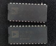
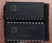
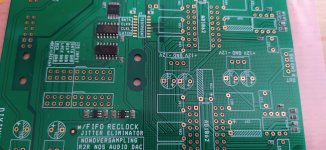
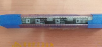
I have found four unused AD1862 and a two AD1865 plus another two used AD1865. The AD1862 were bought in a group buy from Rochester electronics a few years ago.
Please make me an offer for all or any if interested.
I am gifting the two used AD1865 to the buyer of the other two as I cannot test them and also including free of charge, my own dual TDA1541 dac pcb with I2S input (from an Ian Canada PCM to I2s interface.) and a dual AD1865 pcb (has a short marked with a dot).
Hi,
I've purchased a generic NTC-based soft start board from local store. It seems to work. Just wanna make sure that it behave correctly.
At cold stage, there are three NTC adds about 30 ohms to the load. When I put power in (220v AC), the output also reach 220v immediately. Then, NTC resistance decrease and then the relay kicks in to bypass the NTCs (resistance drops to zero) within 3 seconds of power on.
So, I tried connecting power amp to the board. Amplifier's VU meter still kicks hard when turning on. I use clamp meter to measure current, there is not difference between with and without soft start circuit. I don't have oscilloscope to see the wave form and I think my meter is not fast enough?
I thought that the voltage should slowly and reach full voltage. The local shop said that it is normal behavior since it is for amplifier not for AC motor which use reduced voltage method. They said that its limit the current not voltage... Is that right??
I'm looking for a USB to I2S adapter - is there such a thing?
My wish is to find a way to experiment with PCM1808 I2S ADC (which I plan to use directly with a microcontroller for a project), but I think starting with a PC host under Windows (or Linux) (rather than a microcontroller) would better help me get started (reduce the number of variables before involving a microcontroller which itself would have variables.)
My preferred hardware solution would be PC <-> USB <-> I2S <-> PCM1808 <-> Audio source (analog stereo)
Under Windows, I think this would be Windows sound microphone device <-> USB I2S adapter device <-> PCM1808 <-> Audio source (analog stereo)
Thank you for any suggestions or requests for clarification; if there is a better place to explore this topic, I would appreciate your advice.
I've been hunting for this but I've came up dry. I just got an ppp 6550 amp. Its a audio research d115. When I turn it off I get a click then a loud thump out of the speakers. What is the usual cause for this? I'm guessing its carted by a cap discharging but I'm not sure where to begin to find it. Its a loud enough thump to get me worried about my GPA 416's its driving.
I’m wiring up a Behringer crossover which can be connected using TRS or TS phone plugs for balanced/unbalanced operation.
It’s just for a bedroom so no issues with long cables and I realise Behringer is just cheap stuff
but since I have to buy the plugs I’m wondering if there is any benefit to the balanced connection. The source and power amp (not yet purchased) I believe will have the same arrangement so it will be all balanced or all unbalanced.
Attached are parts of the schematic showing the input and output sections so I’m looking for advice on the best arrangement both for sound quality and electronic design.
Cost/time and effort is of no concern but I guess the TRS arrangement is more flexible because it can be easily converted to TS.
Selling a 26 preamp. £285. Three switchable inputs, Holco resistors, teflon coupling caps, DC Link PSU caps, Rod Coleman filament regs for filament bias. All premium parts. Output impedance is around 8K so would drive amps with input impedance of 50K or more. Industrial styling so you don't have to pay for the fancy casework!
Selling on sale-or-return. Can be returned after auditioning within a week or so if it doesn't suit your system, as long as you pay return post and it arrives intact. I have spare 26 valves, ST or globe shape.
Collection preferred from Kensington, London but no problem to post it. Andy
I had an idea to get a Mini DSP 2x4 and run that into the L and R channel of my Parasound amp splitting the signal between 2 drivers (woofer/mid and tweeter or sub and mid). I could just fiddle with the DSP channels to get everything adjusted properly and sounding (and measuring) smoooooth. Once I got that, I could basically just build a physical crossover to match my DSP settings and stuff that in my speaker. The biggest assumption is that my DSP settings will be able to accurately be duplicated (with minimal effort and correction) with electrical components AND that my Parasound amp does not add any eq/color to the signal. Thoughts?
Hi all, I'm a beginner in this DIY speaker area and I have a few questions wanted to be clear about. I'm planning on building a small speaker system with 1 tweeter and 1 woofer on each channel. I recently found out that I can use a capacitor instead of a crossover for the tweeter. But I have to be careful with my choice of the tweeter and the capacitor. I'm currently having a mid-bass driver (40hm - 20w) and a Pam8610 module. My question is, should the tweeter and the woofer have to have the same Impedance (4ohm)? if it is, how can I know what kind or value of the capacitor I need to use. ?
I was gifted an amp, looks like it was repaired once before maybe, at least modded before shipping when I compare to other boards. I can’t seem to find the values for the capacitor at below area. Any help finding these values would be great.
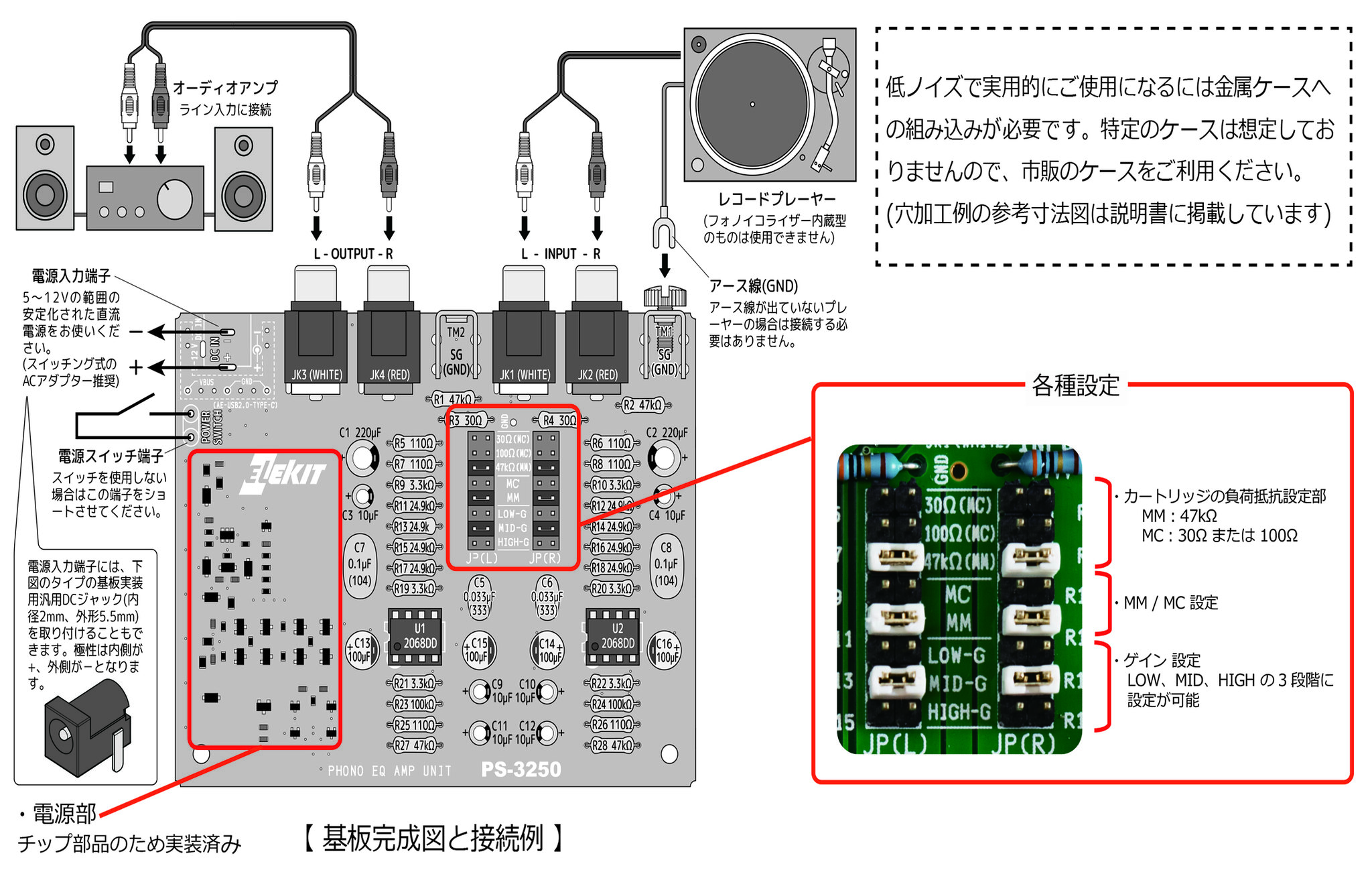
ELEKIT PS-3250 Phono stage MM/MC $105.00
PS-3250 works well with TU-8200
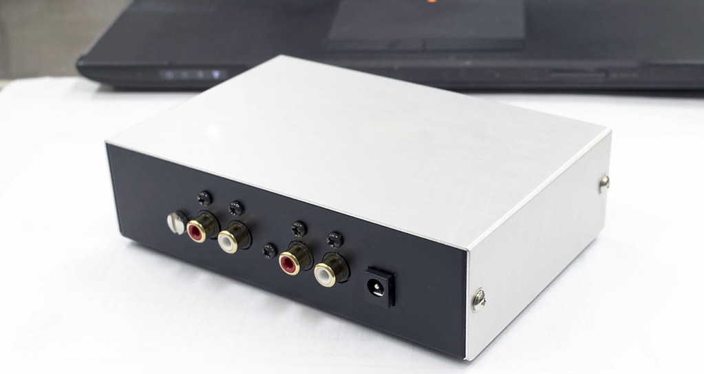
Itatakachi YM -150 case + the DC input socket +PS-325. All for $195 (available NOW)
The box set includes; $195
1. ELEKIT PS-3250
2. Metal box x 1 pcs Tatakachi YM-150 (pre-drilled)
3. DC jack x 1 pcs
4. Switching AC adapter (5V1A) x 1 pcs
5. 3P toggle SW : x 1 pcs
6. Screw M3 x 6 : 5pcs
7. Alternative source of power supply : USB type C adaptor - to use phone battery ADD: $7.50)
. Cartridge / MM type (about 47 kΩ), MC type (about 100 Ω or 30 Ω)
. Circuit configuration / CR type equalizer (RIAA), two-stage op-amp
amplification
・ RIAA deviation / within ± 0.5 dB (20 to 20 kHz)
・ Gain (@ 1kHz)
27dB (MM, LOW-G), 32dB (MM, MID-G), 36dB (MM, HIGH-G)
56dB (MC, LOW-G), 62dB (MC, MID-G), 65dB (MC, HIGH-G)
・ Non-clip maximum output (@ 1kHz) / 9V r.m.s.
・ Power supply voltage / DC 5-12V
・ Current consumption / 100mA (at 5V), 30mA (at 12V) [with NJM2068DD]
・ PCB size / 100 × 80 mm MADE In JAPAN
Features ]
● In addition to MM type cartridges, it is also compatible with MC type cartridges by replacing jumpers on the PCB board.
The gain can also be set in 3 stages according to the output of the cartridge.
● The op-amp is NJM2068DD (low noise). The op-amp can be replaced, and you can enjoy the fun of op-amp rolling.
● CR type is used for the equalizer circuit, so even if the operational amplifier is replaced with another one, there is no concern that the equalizing characteristics will shift.
● Adopting ± 1% metal film resistors and ± 2% film capacitor, RIAA deviation is small and low noise.
● The power supply section is equipped with a positive / negative voltage generation circuit. High sound quality and wide dynamic range are secured by supplying ± 15V to the op-amplifier.
● Equipped with a POP noise suppression circuit when the power is turned on / off.
● Since the level of noise (especially hum) is greatly affected by the routing of the input / output lines and the ground point of the equalizer amplifier, this kit comes with an input / output jack for mounting on the board, and a grounding bracket.
Prepare PS-3250 first by soldering it. You also require these parts that are not included in the kit: DC jack, aluminum case, M3, and 5 screws about 8mm long. These parts are included if you purchase the $99 package.
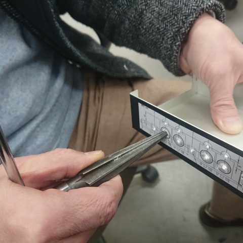
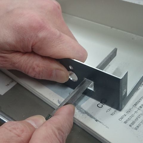
For metal processing your will require center punches, reamers, metal files, drill bits for aluminum and drills.
takachi ym-180 case (pre-drilled after July 11, 2021)
DC 12V (solder the DC Jack - does not include in the kit)
The DC jack used has an outer diameter of 5.5 mm and an inner diameter of 2.1 mm.
The inner pin is positive and the outer and outer peripheries are negative.
The AC adapter uses the same standard plug, 5V-12V.
"2.1mm standard jack".
USB power source - from phone power or battery pack
Case Preparation (as at July 11, 2021... Pre-drilled)
1. Make a copy of the floor plan found on page 4 in the menu
2. Cut out the floor plan and attach it to the back of the case
3. Follow the guides on the floorplan to drill the holes on the case
This Harmon Kardon HK-3390 receiver sat unused for around 5-6 years and working fine when put away. Moving forward, a few days ago, plugged it in and took about 15 to 20 on/off times for it to "kick" in. Powering it on, the light would go from stand by to on but no display or relay clicks and after 5 seconds back to stand by. Eventually after so many tries, it does power up and when it does, is business as usual, sounds great and it might play anywhere from 5 minutes to hours before shutting down again on its own.
What I have noticed going inside... no overheating, idle current around 20mv on both channels, speaker terminals DC -15mv and -27mv. This happens whether the Pre in and Pre out jumpers are on or not. On a couple of occasions, the display has read.... "Check Input"
Who knows about the sound of the follow listed amps? 404 Page Not Found - HigherFi
and the sonic different to Mr. Pass top class power amplifiers from the Aleph / X / XA series
Hello, being on the budget for a preamp, i just acquired a model 2 from Forte. I am particularly interested to the phono stage of any unit as I do not have CD anymore (;-))
Is it worth to upgrade caps? Or better save the money and ask father Xmas a Threshold Fet 9?
In other words, can this unit modded sound in the league of the majestic Fet9?
Thanx so much
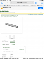
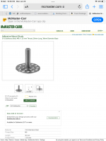
I’d like to build up various umbilical cables. Two parts..
1. A wire wrap that tightly bundles the wires.
2. A tough but relatively flexible (plastic?) sheath, ideally also tight to the wrapped, bundled wires ..something like heat shrink, but thicker and tougher.
First of all, hello from me - this being my first post and all.
I was wondering if some kind soul could suggest a source for decent quality knobs. I am looking to install an Alps RK50 pot in a simple home made passive pre-amp. However, beautiful bit of kit though the RK50 is, it has a rather non-standard 8mm shaft and all the knobs I can find are 6mm.
hello everyone
i have an Stk 4211 2. Stk 402-230 and STK 402-30. ic's
would like to buy there amp pcb's or order them , also the preamplifier/s for them speaker's protection and line in line out. also digital to analog converter
i might use a DVD player for that it has an digital volume control and line out analogic and some codecs already installed just doesn't have line in nor Bluetooth could add something ...
thanks for your help.
Hi can anyone recommend a source for hardwood. I dont need a large amount but I would like to make some really nice tops for my speakers out of really nice 3/4 hardwood. Thanks.
Hello everyone! I'm having trouble finding a replacement laser pickup for my Kenwood dp-m98 CD player. Can anyone tell me what other models of cd player has this, or where I can go to buy one? Any further info in general would be greatly appreciated. Thanks in advance.
Bear with me here fellas.
I’m unemployed and need some projects to keep me busy and my sanity.
I want to experiment with adding bracing to my speakers. Don’t worry it’s completely reversible. No drill holes or anything.
But I also want to do this scientifically as much as possible.
What instrumentation do I need to measure for speaker cab resonances?
I want to be able to add some bracing and then run some merriments to see if it scientifically helped or hindered.
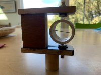
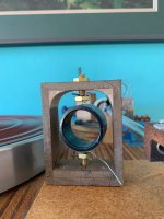
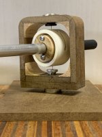
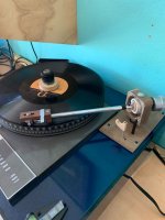
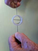
There are several string-based tonearm designs including Frank Schroeder's magnet tensioned, Pete Riggle's Sring theory, and Wm. Firebaugh's Well Tempered and there are probably others possibly going way back, but I think Cat's Cradle may be a new one. It's evolution started years ago in response to Frank's arm. I built a clone of that, but wondered if the string could be directly tensioned to eliminate the magnets. I built one that worked after a fashion, but it had problems involving two parallel strings wrapping around themselves as the arm moved. I wondered if a single string suspension might be possible, but didn't follow up until I mentioned it to nocdplz (Carlo) who suggested I take up the idea again. First I had to confirm that a single string suspension was possible and after that figure out how to incorporate it in a working tonearm.
I had to learn how to place holes in the suspension ring so the horizontal portion would be horizontal. My attitude toward the first effort was lackadaisical because I had low expectations, but it gradually came together and went on the TT. My first reaction to the first LP was "ah, hell." It sounded good, too good to walk away from, so back to the shop for more iterations that led to the version I've used to listen to LPs the last two days. The first two LPs were disappointing, very, but he third was altogether different. What I was hearing from the first two was bad records. The third was a good one and that was what my system with the Cat's Cradle was revealing - good LPs are a pleasure and bad ones got no place to hide.
Especially with the latest version with close coupling, the arm is very stable. The stage doesn't wander, attack and decay sound fine, I don't hear any sound through a mechanics stethoscope placed on the suspension frame.
All of that comes with a big caveat about confirmation bias and subjectivity.
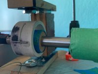
***** SOLD *****I have a SPH main bearing for sale. Looking for A$100 plus shipping. It is the long body short spindle version The bearing is with SPH in Kuala Lumpur in Malaysia.
For full disclosure of the situation please read further.
I bought it a couple of years ago and noticed a squeak once a rotation. I reported it to Sien. I changed to the upgrade bearing and different thrust washers and ran it in for many hours.
I tried thicker grease, heavy oil …… but nothing seemed to work. This went on for nearly a year where I used it on SPH version of the PTP and an original Lenco chasis, before I gave up.
I live in a very quite neighborhood and have double glazed windows, so a small squeak is annoying. Then Covid happened and it sat in the drawer.
A couple of months ago I came upon a brand new SPH bearing for sale in Australia. I bought it at the original cost price of A$290. It works fine and I will keep it.
Last month or so I sent the original bearing back to SPH. He couldn’t hear any problem and claims to have changed the ball, thrust pad and grease. He says it works as well as his new bearings.
Since I can’t get an upgrade to a Thorens 401 bearing this is now of no use to me so is up for sale.
I have already paid for shipping to KL and I am expected to cover return shipping as well, so it would be best if it could be shipped directly to the new owner.
Having lost my money on 2 previous bearing manufacturers I have decided to back off and drift towards using my recently acquired vintage Technics SP10/EPA100.
There's so much stuff going on, with friends and my beloved cat dying in just the last couple of weeks. (I'm still coming to terms with my cat because she was my heart.) Among the flurry of deaths was my neighbor 2 doors down. Her husband stopped by today and told me (I feel so terrible I didn't know) and said he's selling the house because he can't afford it. It's not listed as for sale yet but it's valued at over $500K so I looked up my house and... it's gone up $27K in the last 30 days.
Interest rates are going up. Traditionally rising interest rates are directly reflected in the value of real estate. But now interest rates are (predictably) rising and real estate prices are rising faster.
Obvious inflationary signal but is this a long term trend? Prices have been going up for a while but this is crazy.
I am trying to repair a Sony CDP-CX350 (aka Mega Storage. The display is very faint. Parts for this model are no longer available new so I am looking for a broken one that still has a good display to cannibalise for parts. I specifically need the display board which contains the VFD and its driver components. There are a lot of these players for sale in the US in a non-working state for under $100 which I could probably justify but the cost of shipping and import fees to Europe come to two or three times that on top. I really need to find the individual board on its own to keep the cost down. Any ideas where to look? Getting used parts for cars is easy but used parts for old hifi is hopeless.
Looking for a pair of Magnequest RIT-5 parafeed interstage transformers in M6 or cobalt laminations.
Some say it's the worst coupling option, large cap with transformer and LC tunned circuit in the signal path. My intuition is telling me to try it out.
This cromo12, I am working on has the tweeter working but the woofer has no sound. I checked the woofer and its not blown. I opened up the module and there are 2 ICs (TDA8950). One is marked U6 and the other U9. Can someone tell me which IC is driving the woofer. Please assist.
Does anyone know the driver used in the array? If not maybe a similar build with a 10" driver.
I live in Denmark and the shipping cost and import taxes makes the DEBRA to expensive.
It's four boxes and 4 drivers plus a not very expensive amplifier.
Hope to hear from someone that has build something similar
I just got my DATS v3 and measuring my subwoofer its way out of spec from what the manufacturer says. I took it out of the box and hooked it right up to the DATS so nothing inline, crossover or anything. The FS is 17% different, the QTS is 33% off, the QMS is 40% off! I know these percentages are relative and .31 and .48 may not mean everything but the FS is substantial enough. I just have the sub sitting on the floor with the vent exposed, am I measuring wrong? I took 3 measurements, 2 are shown and the factory specs are on the right.