Rise time and distortion have a relationship with regards to the band pass of the design. Beyond the HF band pass of the design, distortion components which are a series of higher frequency multiples of a fundamental, are suppressed. Therefore out of band distortion components are affected by rise time. Rise time is the equivalent of a filter response.
Conversely, in-band distortion components are not affected. So if the discussion is about in-band distortion, then rise time and distortion are not related. Overall distortion measurements can optionally include out of band components. Therefore, bandwidth limits are quoted for measurements.
Conversely, in-band distortion components are not affected. So if the discussion is about in-band distortion, then rise time and distortion are not related. Overall distortion measurements can optionally include out of band components. Therefore, bandwidth limits are quoted for measurements.
Can someone here explain how these two parameters relate to each other? For example, how can you have 6u sec rise time with .002% THD?
Well, .002% THD measured (or spec'd) at what frequency ? At a lousy 1kHz ? Then yes, you could have a slow rise/fall time and THD still looks reasonably good at 1kHz.
It is however a totally different matter if you measure and spec. THD at let's say 20kHz. There you will see an average amp separate from a really good amp.
An amp with a lousy 6u sec rise time may have a frequency response of barely 40kHz and with that THD performance at higher frequency above 1kHz is likely very unimpressive to really poor and so such amplifier will not sound clean or crisp but very mushy like average amplifiers do.
Generally can be said the faster an amp is the more potential this amp has to achieve a very low THD at higher frequencies. At frequencies where the program material has most stereo image and information. If we consider that an amp must be able to reproduce the 5th harmonic (of 20kHz) that makes the frequency response requirement of an amp to be at least 100kHz.
If the rise/fall times (another way to say slew rate) of an amp is inadequate for the signal being amplified, you get gross distortion (its a form of clipping/overload really, but internal to the amp).
Rise and fall times depend on signal amplitude, its better to quote the slew rate which is signal independent.
If the slew rate is adequate then there is no reason any distortion is added as there is no internal clipping, the amp is still in control.
A 30Vrms 20kHz signal has a max slew rate of 5.33V/µs, corresponding to a +/-50V rise/fall of 18.75µs. Most amplifiers operating at this voltage level will have slew-rates of 10 to 50V/µs - ie slew rate limiting doesn't happen for normal signals in (sensible) amplifiers, not even vaguely close in fact as HF signals are much lower than full-swing.
Feeding a square wave into an audio amp is taking it outside its normal regime, nothing meaningful about distortion can be gleaned, but something about stability and the slew-rate can be infered.
Most music signals are not square, microphones don't generate square waves. Synthesizers can though, and should be LPF'd on the output for this reason.
You could also argue that one has nothing to do with the other. It's very well possible to have an amp with very short rise- and fall times yet a lot of distortion. Rise/fall is typically related to square wave testing; for audio signals with a freq range up to say 20kHz you wouldn't talk about rise/fall but about slew rate. A 20kHz full level signal has the highest slew rate requirement, for example a 20V peak signal at 20kHz has about 2.5V/uS slew rate.
If the amp slew rate capability is at the same order or lower than the requirement for the signal, you start to get lots of distortion.
So, for low distortion you need high enough slew rate but it is not enough, there are still other distortion mechanisms internal in the amp. And to get high enough slew rate you need good high frequency performance which would sort of automagically lead to fast rise/fall. But fast rise/fall in itself does in no way guarantee low distortion.
So did I confuse you sufficiently? ;-)
Jan
Rise and fall times depend on signal amplitude, its better to quote the slew rate which is signal independent.
Mark I think it is the opposite. Rise/fall is defined as 10% to 90% of signal amplitude, with no relation to absolute level.
Slewrate as V/uS obviously depends on level; a 10V peak 20kHz is ~1.25V/uS, a 40V peak 20kHz is ~5V/uS
BTW fully agree with you on the filtering stuff.
Jan
Mark I think it is the opposite. Rise/fall is defined as 10% to 90% of signal amplitude, with no relation to absolute level.
Slewrate as V/uS obviously depends on level; a 10V peak 20kHz is ~1.25V/uS, a 40V peak 20kHz is ~5V/uS
BTW fully agree with you on the filtering stuff.
Jan
The 10% and 90% are (in a hidden way
") ) related to the absolute level used for the signal.
) related to the absolute level used for the signal.Slew rate is usually given as the maximum available rate of change, so signal level is not of relevance (beside the obvious, that the signal must be able to evoke slew limiting, a condition we all try to avoid).
Mark I think it is the opposite. Rise/fall is defined as 10% to 90% of signal amplitude, with no relation to absolute level.
Slewrate as V/uS obviously depends on level; a 10V peak 20kHz is ~1.25V/uS, a 40V peak 20kHz is ~5V/uS
BTW fully agree with you on the filtering stuff.
Jan
It depends if you are thinking about the slew rate limit of an amp, or of the max slope on a signal - I'm only worried when something is limiting, and that's the going to be the amp!
Last edited:
Yes, but the slew rate requirement of a signal is level dependent; a 20kHz 20V signal has its highest slew rate at the zero crossing of about 2.5V/uS. At 40V it is 5V/uS; at 10V it is about 1.25V/uS. I don't see how that is anything but level dependent.
I agree that the slew rate capability of amp is not dependent on signal, it is a parameter set by the design.
Jan
I agree that the slew rate capability of amp is not dependent on signal, it is a parameter set by the design.
Jan
In the absolute (and in theory), they have no relation with each other until some frequency is reached: with 6µs, it is about 50~60kHz.Can someone here explain how these two parameters relate to each other? For example, how can you have 6u sec rise time with .002% THD?
A system with such a rise time will struggle to reproduce frequencies above 40 or 50kHz, independent of the amplitude.
Below that, there is not going to be any theoretical impact on the THD.
For example, digital transmission chains like 44k have a much more limited bandwidth, yet they can have tiny amount of THD up to respectable frequencies.
As mentionned earlier, practical systems are also limited elsewhere, in the SR, but that is mostly unconnected.
Some amplifiers can have a large small signal-bandwidth (hence a short rise time), yet be severely SR-limited
Not at allI take it that this is impossible?
You could in principle achieve 0.2ppm in this format, or even less, and the 40k limit could even help, depending where it is applied.
Even disregarding the location of the 40k limit, it could be helpful, because some intensive FB schemes can severely limit the HF performance to improve the purely audio performance in a limited bandwidth.
That is something that should work ideally with the current, band and slew-limited reproduction means, like vinyl, digital, FM, etc
So again, how can you have .002% THD from 20- 20k with 6us, bandwidth limited to 40k? I take it that this is impossible?
Maybe not impossible, but let's say very very unlikely.
Soja if we actually compute by BW (MHz) =0.35/Risetime (us) we get in your example 58kHz at 6us rise time. Still not impressive, at all. But better than my initial estimate.
The maximum BW as of in this example is indeed quite unimpressive. Said amplifier has a big problem and that is not only BW. I see no way how such amplifier can possibly achieve .002% THD over 20Hz- 20kHz.
But correct me, if it can.
I think this could be a typo, in your example with 6us a THD of .02% seems more probable.
In my books, with a THD statement there should be a Frequency statement and power statement as well at which THD is true. Something like:
THD .002% @ 20Hz - 20kHz @ rated power
or
THD .0001% @ 20Hz - 20kHz @ 50% rated power
This would be more meaningful and leaves no wiggle room for misstating or pretending.
Generally there is only a single THD statement given and by most it is understood that this THD figure is true at only 1kHz at rated power.
Some mid 80s well known Japanese mfg did the only right thing and deviated from that and specifically made THD statement vs. Frequency vs. Power and proudly published that in cool 3D graph's in the sales prospectus for they're amplifier products. To my knowledge there are not many other mfg's daring to even measure THD at frequencies higher than 1kHz let alone publishing the measurement results.
And sure there will always be the universal excuse, that the speaker distortion is by magnitudes higher than a poor THD figure of a given amplifier. (implying that THD is not that important of a spec.)
This is definitely a true statement, yet does such an amplifier with a poor THD figure sound any good ?
I highly doubt it.
Just a reminder: bandwidthth (=rise-time) and linearity have fundamentally no relationship whatsoever.
They only become connected through amplitude, eg. when the slewrate is exceeded.
That could be the case in practical amplifiers, but we should refrain from drawing general conclusions out of a single case.
I am certain that members of this forum could design an amplifier having a power BW of only 22kHz, and a THD <1ppm from 0 to 20kHz: a very high FB, conditionnaly stable design could achieve it.
Would this be worthwhile?
I am less sure: it is probably simpler, safer and more effective to use a more conventional, higher OLG bandwidth design, but that is just a reasonable assumption.
In reality, rise time and distortion are completely disconnected: if you drive a very limited amplifier way beyond its normal bandwidth, it will amplify nothing, and the harmonics will be amplified even less, resulting in a zero THD.
Assuming of course that only linear limitations are taken into account, which is the case when you talk about small signal bandwidth or rise-time (which are more or less interchangeable)
I am certain that members of this forum could design an amplifier having a power BW of only 22kHz, and a THD <1ppm from 0 to 20kHz: a very high FB, conditionnaly stable design could achieve it.
Would this be worthwhile?
It probably wouldn’t even be easy - a designer would have to go out of his way to do it. Typically, when you get close to the hairy edge of slew limit, distortion would far exceed .002%, which is why the combination of parameters seems unlikely. Unless it is achieved through filtering ahead of an inherently high slew rate amplifier.
Having excess bandwidth is actually an invitation to high frequency distortion. So, filtering out needless bandwidth to end up with a system that can never be 'slew limited' completely avoids slew limiting distortion - the input signal is filtered enough that the amplifier is always fast enough to process it without distortion.
The internal bandwidth and loop properties of an amplifier used in a system do not have to be equal to the transmission bandwidth of that system. Filters placed around an amplifier will always reduce the system's transmission bandwidth to a value below that of the amplifier's simple closed loop behavior, and as was stated before, this is a good thing. Why present signals to an amplifier that it can't handle? And, why allow an amplifier to pass signals downstream that no device needs to ever process?
I routinely design a lowpass frequency of around 100-200kHz into my circuits, yet I like to use amplifiers with 50-100MHz gain bandwidths, in order to get adequate feedback and thus low distortion. Besides the basic 100-200kHz lowpass, I also like to use capacitors that have good performance (hopefully nulls) at cell phone frequencies, as well as adequate rejection at other broadcast frequencies. As a result, I never have RFI problems operating the circuits, even outside of a chassis. A circuit's transmission bandwidth is only a small portion of what determines how well a circuit performs, and higher bandwidth is often detrimental.
Easier than you think: this quick and dirty example has a THD in the ppm region, yet is already slew-limited at 30kHz:It probably wouldn’t even be easy - a designer would have to go out of his way to do it.
Attachments
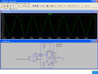
^ I am sorry to say, by just eyeballing the signal waveform above, it appears heavily distorted.
I don't see how your THD result for this example can possibly be in the PPM region, I think something is wrong with this simulation.
Signals that are distorted so bad that it stands out to the casual observer have a very high THD figure, in the order of single to double digit %.
I don't see how your THD result for this example can possibly be in the PPM region, I think something is wrong with this simulation.
Signals that are distorted so bad that it stands out to the casual observer have a very high THD figure, in the order of single to double digit %.
- Home
- Amplifiers
- Solid State
- rise/fall time and THD