Hi
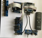
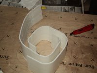
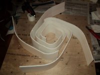
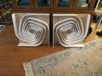
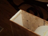
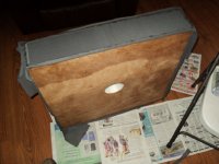
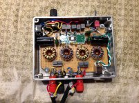
in attach the first proto of 300B OT with nano
It is 3k primary
5 ohm secondary (single)
Around 40H -100Hz but some adj with gap will be possible.
At the end it will be potted.
The first test are almost fine.
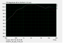
The Freq. answer; there is a little step at 50kHz, but it will be fixed
Zs are 700 ohm (blu) and 1 kohm (red)
At thr moment out of the power stage that will be ready soon
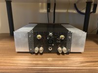
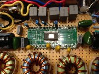
I saw a simple amplifier but thought maybe I can do it better without to many components.
Here is the result. Its not very temperature stable but in class A it gets less hot the louder you play.
So it is just to measure the current in the output transistors = voltage over R8 or R9 and adjust it with P1 to
a little more than Feed voltage / 4 * R speaker. But take half an Hour for the heat to be stable after the last adjustment.
It is easily adapted to other voltages and speaker impedances. Distortion is about 0,1% which maybe some people don't hear.
Noise is extremely low under 5 uv 20 - 20k. Common mode rejection is determined by C2. Frequency response is good 25 Hz to 95kHz -3dB. View attachment 1418335
But looking at the results it is possible to do it much better. Faster and much lower distortion but a little more noise.
The problem now is that the P1 is very sensitive in adjusting the current.
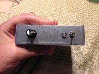
Now the anti thump + radio interference filter on the input is included. But still pretty simple.
I changed the R12 to 0,82 ohm because I believe the IRF 540 has about 5S at about 1A.
Hey I'm having trouble understanding exactly how I can control volume from my TV remote. I really wish TV's still had a volume controlled RCA analog output but here we are. I only have an optical out and HDMI ARC port. Is it possible to use one of those HDMI arc to analog audio converters so I can use the RCA output to my amplifier and control the volume with the TV's remote?
I'm looking for a schematic and any info for an 8 Channel Delco amplifier from an older Peterbuilt heavy truck. I think it may be the same as the older GM Monsoon systems used. It's an 8 channel amplifier with built in crossovers. It uses eight Delco 82452 chip amps. This one won't power up and the head unit is displaying "Check Amp Fuse".
I'm confused because I see microphones placed one meter away, and others only 20cm from the speaker.
And while we're at it, any advice on what to take to measure with quality.
the latest generation sound card, which should also be purchased, but I already have clearer ideas, will have the best features.
I just installed REW
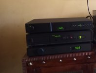
I have a Quad99 system, with AE speakers, which yields a sound akin to analogue and I love it. Unfortunately, the CDs have started to skip after a minute: everything is fine, then it stops and the display goes ape with numbers randomly flashing on the screen. I suspect the laser lens is playing up. I use a CD lens cleaner but it obviously is not man enough to do the necessary. So, do I buy a new CD lens cleaner, or open the CD player up and try to give it a good clean (compressed air? vacuum?). Or, as it seems to work fine for a minute, could the laser lens transport be at fault? If so, how can I confirm?
Has anyone had a similar experience? How easy is it to get inside a Quad99 CD player? Any suggestions???
Cheers
I’m working on designing a Class H audio amplifier with a power output of 2000W RMS at 4Ω load, and I need some guidance from experienced designers.
I've previously designed a a 800W RMS Class AB amplifier for outdoor applications. Now, I want to develop a high-efficiency Class H amplifier for professional audio use.
Key Requirements:
✅ Output Power: 2000W RMS @ 4Ω
✅ Topology: Class H with multiple rail switching
✅ High Efficiency & Low Distortion
✅ Stable Power Supply Design
✅ Thermal Management & Protection Circuits
I’d appreciate any insights on:
🔹 Proper rail voltage selection for efficient power switching
🔹 Best MOSFETs/BJTs for high power handling
🔹 Reliable protection circuits (Overcurrent, DC, thermal, SOA protection)
🔹 PCB layout guidelines to minimize noise and EMI
🔹 Any reference schematics, simulations, or design resources
If you have experience in designing high-power Class H amplifiers, I’d love to hear your advice! Feel free to drop suggestions, references, or even share your past projects.
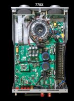
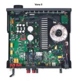
The Mission 778X is based around the design of the Quad Vena II and Leak Stereo 130 which both use the LM3886 as far as I know. Looking at internal pics I can see 6 forward pins on those two but the 778X has 8 forward pins so maybe a TDA7293? Specifications are similar for all the amps and are made in the same IAG factory. I assume when the 778X was designed, the LM3886 supply issues came into play.
I can't see enough through the vent holes and as it's new I do not want to remove the cover as well I do not have a Torx bit small enough.
I'm not an expert on SPDIF nor transmission lines, so bear with me please!
Background:
My good old well working Audio DSP has a digital output port with CS8420 feeding a AES3 (with TXP & TXN) and a Cinch (75Ohm) Output (with TXP) in parallel at Pin26.
The picture "original" shows the output schematic as far as I could analyse the (4-layer) board (pretty obviously with supply and GND layers). GND on the board is split between the output connector area and the circuit area (for unknown reasons) bridged with 0Ohm parts.
My Plan and request for confirmation or advice what to do:
The DSP is planned to drive 5m/15ft long koax stereo SPDIF BNC connections to each of my stereo speakers sporting digital 4-way "mono" x-overs. I.e. whether the speaker is "left" or "right" is selectable in the speaker. So, basically I need two parallel BNC Outs (would remove the cinch connector and disconnecting AES3 circuitry).
Please kindly have a look at the schematics and options I have come up with. I am sure my stuff needs changes to work properly, so I would be very grateful for recommendations "how to do this right".
Thanks a lot for reading all this and I hope you care to answer with any helpful recommendations.
Regards,
Winfried
Looking for 1pcs 2sk60 rank 5 or 6.
Can also trade for ...i have 100pcs 2sk170, some Black Gates, good European triodes, new in box ecc82 Telefunken, e88cc, ecc83, 3pcs rda1541
I have also 1 set of D3 tda1541 boards with 50% ,parts.
Maybe chinese board heavy modified es9038q2m with first generation Bisesik nanocrystalinev output transformers hi-fi tunimg silver gold 10A fuse new in box.
Thank you.
First, forgive me that I have not posted here in ages. I'm looking for help with my much loved Threshold FET ten/hl preamp. In my system the outputs of the FET ten/hl are connected to a homebrew converter using Jensen JT-6110K-B 4:1 stepdown line input transformers. The balanced outputs from my transformer box feed a pair of Schiit Tyr monoblocks.
The problem is I have been measuring about a 5 dB drop off from 40 Hz to 20,000 Hz at the outputs of the Tyrs.. My first thought was the problem might be caused by excess capacitance in the cables running from the transformer box. I swapped out cables. I removed the transformer box. I swapped out a lot of things. The only thing that fixed the drop off problem was disconnecting the FET ten/hl and putting in a different preamp. Nothing else made any difference.
I've recently came across a new cheap little component tester that does way more than just the usual few basic tests.
This little beauty also can do basic DSO functions and is also reasonably accurate. There's also a signal generator and a full set of electronic diagnostic testing, including cap leakage/ESR, full inductor parameters and decoding IR remote waveforms, automatic pinout recognition of just about any device, including IGBTs, SCRs, diacs, triacs, all sorts of diode types, etc etc etc.
It run off an internal battery rechargeable through USBC and includes cables,, probes and connectors. The menus are very easy to navigate through and most tests are done very quickly. I've been trying to find specific devices it doesn't recognize or can't test. So far I haven't come across any (excluding ICs, but it will detect some lower voltage 3 pin Vregs!)
The best part is this tester is that its quite accurate and only costs $43!!!
Hi everyone, I'm a new member so let me tell you why I'm here! Since last year I started collecting vinyls and eventually found myself getting into audio equipment but I'm new to this, never really made any repairs myself. I know the basic of electronic but it's all text book, never really tried it out in real life.
For now I want to work on amplifiers mainly for turntables that I found in thrift stores or on marketplace.
I'm a 2 year student of Ho Chi Minh university of Technology, Electrical & Electronic Faculty. I have passion on making amplifier so that is the reason why i choose that faculty.
It's nice to meet youuu.
i have acquired a dynaco 150, she in a bit of a sorry state due to the previous owners tinkering, it runs but has intermittent noise in one channel, so instead of the usual recap and rebuild i was wondering if anyone had used the chassis and transformer and built something completely different inside, maybe a leach? not really interested in the update my dynaco path. so fire away, who has done what and what are some ideas. cheers.
So I have an unfinished over-the-top preamp project that I never finished using kit that is now un-obtanium. What is needed left to do is mount the Raleigh boards to the Bent chassis and wiring it all up. I am not sure what is a reasonable price to ask for this and would appreciate feedback regarding pricing, hence this post. Not sure if that is onside or not. Of course, I could bust out my soldering iron and wire it all up and sell it complete, but I don't seem to have the time and I am a bit unclear the best way to handle grounds when merging the two kits.
Bent Audio full balanced TAP-X with Slagleformers
This is loaded version of the Bent TAP-X, which has four Dave Slagle autoformers inside, fully balanced input to output. It has 4 balanced/2 single ended inputs, 2 balanced/2 single ended outputs and operates seamlessly switching among them. This one also has the Larger and Deeper Case, which permits a DIYer to add to it**. The TAP-X provides 1db steps and +7db gain, though passive. It comes with the very classy and heavy aluminum remote that switches all front panel functions.
Paid $2500 in 2014
**K&K Audio/Raleigh Audio Extreme Linestage Premium Version Kit with amorphous core iron, 6H30Ps, upgrades caps and resistors.
Kit includes Premium Line Stage assembled and tested by factory. Lundahl LL1674 amorphous core Output transformers, Lundahl LL1676 amorphous core input transformers (assembled on their own board), Lundahl LL1683 power transformer.
My kit does NOT include Analog Input Board and Select Switch, 12V Relay Power Supply, the Stepped Shunt Attenuator, nor the Raleigh Chassis from the Raleigh Kit as these tasks are all provided by the TAP-X above.
Paid $2000-2500 back in 2014. I still have the instruction manuals for each, if I can locate them. I have the Schematics of the Linestage and PSU as well from Dave Davenport. What is needed left to do is mount the Raleigh boards to the Bent chassis and wiring it all up. Also, the top plate of the bent chassis will need some holes to allow the Raleigh kit to breathe if you want to keep the lid on. I bought this before a major move and then never finished the project before moving permanently into the full active speaker setup (JBL M2s) which doesn’t require a preamp.
If you had a preference in a waveguide equipped dome tweeter, which one would it be?
It could be a tweeter that already comes with a WG or a combination of tweeter and WG you came up with.
There are a few which IMO are an afterthought just to be trendy, but tweeters which are engineered with the WG as a complete design are actually not that abundant.
My favorite soft dome in a WG is the Morel CAT378. It just does everything really well and can be crossed sucessfully 1st order with just one 3.3 - 5.6 uf cap. There is enough dampening at Fs to not need an LCR, but I still prefer one.
***** 03/03/2024 Update of project scope => move from UAC1 to UAC2 ******
Hello,
I'm putting on the bench someting in my head since a long time, that should not be too difficult to achieve for ones with know how... but could not be as easy for me ;-)
I want to program a "simple" USB to I2S, 8 channel device, UAC2, single sampling rate (48kHz or 44.1kHz), with Asynchronous mode.
Why UAC1: because ST proposes some UAC1 libraries, and no UAC2 ones (at least officially). UAC1 works without drivers on Windows and Linux.
SB Full Speed (FS) allows for 8x 48kHz x 1- bits (or 4x 48kHz x 24 bits). Great Monitor studios like Neumann KH150 have internal single 48kHz sampling rate. Many people consider that CD quality is "sufficient" and don't race for more bits, more Hertz. It is easy to find stm32 boards with USB FS, and more difficult with USB HS.
This would aim at providing the connectivity part to a 8ch DAC like ES9080 or AK4458. Overall target is 100% function and 99.5% performance of top products. for that niche need of multichannel. It could pair with RPi / Linux DSP offers like CamillaDSP for active speakers (or speakers / subwoofers combos...).
Plaform is a STM32F4 dicovery board to start with, then could be a STM32 black pill (seems to fit the purpose), which pave the way to dedicated board if needed. Those platforms unfortunatly have SAI, but if done well, the different I2S peripherals can be synchonized as slaves from a master, or all slaves from an external clock. A blackpill could be the USB "module" of a DAC board.
I would be happy if the the code could rely "as much as possible" on HAL libraries, code generated by STM32CubeIDE, and ST USB middleware. But, why did they made that so complex, with so much abstractions, while still needing to dig in all "layers" to fit/finalize code, and not really robust... I reallydon't like it so much, and it does not looks nice to me. But it should ease future portability (at least try to).
Intention is Open Source for the application part (not an expert about ST "mixed" licence for the USB stack but should be OK for DIY community).
Oh, if it already exists on Github or elsewhere, and I have not found it: let me know. I will be super happy ;-)
Current understanding is that, based on existing stereo code, I only need to:
find all locations where the number of channels impacts the code
change the nuber of channels from 2 to 8,
ensure the consistency of the buffer size,
on periodic basis, slit the 4x2 channels in sequence from the inputs to 4 distinct buffers that will each drive an I2S (through DMA)
Help of people knolageable about USB UAC and STM32 will accept to help... and I may have stupid questions.
I have an almost working stereo code based on ST examples. I have a first version that declares 6 channels, which is not working. I will come tomorrow with some questions...
For sale these amazing speakers based on TB W8-1772 on Bob Brines project.
Speakers easy to drive with detailed sound and a great bass response. Unbelivle.
Up for sale a perfect combo - MINISHARC - COMPACT 4-IN 8-OUT AUDIO PROCESSOR BOARD WITH FIR CAPABILITY, VOL-FP, AN-FP AND DA-FP, MINIDAC8, Remote.
Everything in perfect working condition. I used it as a crossover with my 4-way open baffles.
Very much the same as miniDSP Flex Eight.
Downsizing and don't need it anymore.
More info - https://www.minidsp.com/images/documents/miniSHARC User Manual.pdf
Asking $375 OBO
I am trying to find out how to help the admin of this site. I am not sure if there is anything other than donations that would be of any assistance but if others like myself could all contribute a little it might mount up enough to make a difference. Any ideas?
Hello All!
Found this forum through various searches on DML technology, it seems to be the best aggregation of information on the internet in that regard. Got curious enough about what was so unique about the sound that I just had to hear them. Learned enough to build my first pair and I'm hooked! Came to say thanks and perhaps learn enough to contribute down the road.
Up for sale is a Pair of Waveguide loaded Peerless DA32TX00-08 1-1/4" Corundum Dome Tweeters.
The waveguide boosts around 7.0dB at 1.5k, super smooth.
Condition - just tested as an waveguide prototype.
Asking $200 for the pair.
If you're here, you're probably searching for info on the Toshiba TA7136 (aka the TA7136P or TA7136AP) op amp. You may be having trouble with a device that uses it. Let me guess: is it picking up FM radio? Does it sound a bit fuzzy? Is the noise floor strangely elevated?
Using the spice model of the TA7136 that I developed for the Onkyo, here's the simulated loopgain plot of the tone control reference circuit suggested by the TA7136 datasheet. It's really bad: simulated phase margin and gain margin are zero, as the loopgain phase crosses through -180 degrees right at the ULGF around 1.6MHz.
It's possible to design a circuit around the TA7136 with generous stability margins, and retain plenty of in-band feedback; Toshiba just didn't bother. It's yet another example of bad datasheet reference circuits informing bad mass-produced applications.
Has anyone built a class A amp with SMPS
I thinking of building A LuFo stereo amp with a SMPS LuFo Amp - 39w SE Class A from 28v Rail
I have a SMPS 30volt(variabel) that can give 10A.
But Im thinkig of the heat it Will generate...
I've replaced both the tweeter and the woofer in my Ruark Equinox.
I'm now using:
Scan-Speak D2905/970000 'Classic'
SEAS E0042-08S (W18NX001) 'Excel'
They were the closest matches to the originals.
However, the W18NX001 drivers suggested in that thread are 8-ohm drivers, while the originals were 6 ohms.
I'd need to redesign the crossover to compensate the difference...
I will share the current design and would appreciate your input.
Also if anyone else has done this change on the equinox please share your experience
Hello, I recently acquired a pair of these in great condition. They have a couple issues, but hopefully not a major problem.
I have the full build and owners manual along with schematics
1. The LED's that turn from red to green on the preamp board are out and will need to be replaced. The part number listed in the manual HZ-MNT LED with a 895000 designation. I am having trouble finding this at mouser with this number, although there is a 895006 that comes up as a led that hey stock.Any help sourcing these would be much appreciated
2. I have a minor hum coming from one of them I have not moved tubes around to see it they are causing it. This leads me to my next question. Does this need to be recapped? It was produced somewhere around 1995.
3. If there tubes in it are original, should I just buy new ones?
4. How can I ensure that there is no residual energy in the amplifer so that I can open them up and look around, I wants to listen to them, not have them take me out haha.
SOLD
Miro USB interface stack PCM1704 DAC board for sale.
A pair of PCM1704 with one white dot => J graded chips on the board, and these are very difficult to source these days. These are recycled chips from a reliable seller, removed with proper care. They are not bought from random sellers in Ali or ebay. They work properly and nicely.
Parts has been carefully selected and high quality ones are used. eg. Wima film, Nichicon FG and KZ, Vishay tantalum resistors for the I/V.
What you need to provide :
1. Chassis, wires, connectors etc
2. You will need to give it PSU with rails +/-5V (Analog) , +/-5V (Digital) and +/-10~12V (IV Op amp supply)
3. Compatible USB-I2S interface board that can be stacked on the DAC board, which are not offered in this sales. The two such devices are : I2SoverUSB v.III Fully Isolated outputs or York + Reclocker
4. Two single op amp for I/V stage, which are not offered in this sales. Eg. OPA828 is a good one for this DAC.
Payment by PAYPAL FF only please.
DAC + shipping registered & tracking = 230 USD or preferably 300 SGD (Singapore dollars)
Hallo everybody,
I'm an old man from Italy.
I like music better than hifi, but I often read threads in this forum and I find here good info for my clumsy DIY attempts.
Lately I discovered wtfplay software and I like it a lot.
I wish all the best to every forumer.
Please, forgive my English.
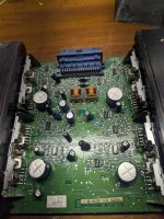
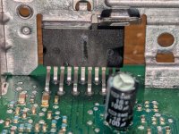
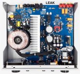
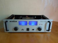
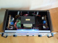
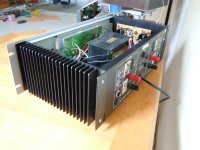
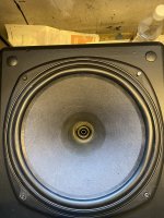
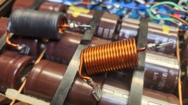
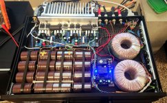
Since I haven't found anything in this forum about this "cheap" PA amplifier, which is very common in Europe, I'll dedicate a separate thread to it, including an explanation and modification suggestions.
First of all: this thing is a stunner, it's very simple, sounds excellent - in my opinion better than the vast majority of analog transistor complementary push-pull products, i.e. almost everything that has been marketed as hi-fi or high-end, regardless of price! Those who measure good sound in kilos (> 14kg) and watts (> 100) are also catered for. Some would have measured 2 x 250 watts into 4 ohms - so here's a tip;-)
I would also advise everyone to try out an existing device first in order to get to know the built up and parts and their sonic effects before attempting big diy projects. So here is a device that costs about 100 euros, can be connected immediately and makes music - within the framework that is commonly interpreted as "high end" - and will be shown some steps that lead to (for many) audible changes.
"However, the transformer is fat! I have 3 meters distance, but after 20 minutes of listening to music I'm exhausted. I will probably remove the transformer and place it 6 meters away;-) This is a general recommendation - to ALL: keep the transformers far away, set up toroidal transformers and point the "hole" towards the listening position (lowest EMF). Many "square" ones have their lowest EMF at the top or bottom, so a steel plate is angled and the transformer is screwed to it tilted. This is occupational safety and health protection! Please also pay attention to your neighbors and children and cats and dogs and budgies and fish and dust mites;-) This is NOT taught in standard electrical training courses"
copied here: https://www.diyaudio.com/community/...e-220-volt-version.368883/page-2#post-7773808
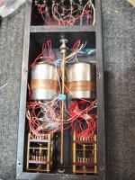
So, sometime in January I bought these classic 30 year old Tannoy CPA12’s after MZM identified the hidden treasures within: Dual Concentric 12-inch 3134’s. To top it all off, MZM has a ML box for these fitting my living room perfectly. And the price was unbeatable @ 500 dollars including an extra tweeter.
But, surprises kept coming. These pics show the drivers upon arrival at my house. Notice the baskets have been painted, and this had been spilled onto the surrounds and in some places also onto the cones.
One of the drivers have had a party with a lit candle. So, these are just to share with you my first impressions.
After a quick listening test I determined these drivers needed more attention. MZM has been my teacher all along, and I his padawan.
Later I plan to post pics and descriptions of my work. I can allready say that a cracked magnet and off centred throat/top magnet assembly had to be dealt with 🙂
Sharing to help others and perhaps motivate to buy these robust classic drivers and fix them up properly. All it takes is time. Nearly finished, but at least 40-50 hours have been spent allready.
These sensitive drivers sing well with First Watt power specs, and Papa loves Tannoy’s too. So for that reason this is posted in the PL section, where the greediest of boyz reside.
Hi guys. 90% of my audio background is car audio, but within the last year I'd like to build a high-end grade solid-state amplifier (scared of tube voltages) and i am sure ill get enough knowledge of it here
Great to be here and thanks for having me!
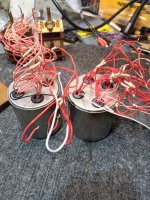
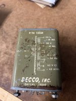
So now that Aliexpress is off limits for this stuff in the US, and my last order came in today with two transformers wound custom just like the specs below except they made a mistake and wound the last tap for 05V and not 15. I'm highly annoyed for sure. I'm sure I'll find a use for them but until then...
Does anyone know companies that wind custom transformers in the US that can produce the following?
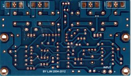
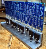
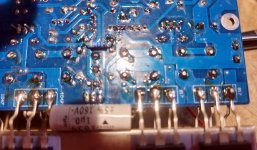
Other threads are talking about this amp, but they refer to older and multiple versions. Confusing.
In my opinion, this amp is so good that it deserves a thread alone.
I bought the DIY version on Aliexpress and replaced all components but the transistors, with good quality ones. I also discovered they are maintaining this 9.2 version, the PCB is updated compared to some other PCBs I saw some years ago.
This amp is based on D.Self publications, and with some super easy mods, it becomes a very good HiFi one.
Good points are the CFPs in the front end, and the triplets in the back end. Both refinements are absent in the newer V10 version.
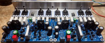
Here is the schematic with the mods. The small resistors I used are all Vishay MBB/SMA 207 professional 1% 0.6W.
I love its sound, very precise, and never harsh. I'm using it all day long, and I compare its sound with the Circlotron's. Very close!
Cheers!
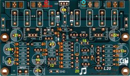
EDIT Apr 28 and 29 2025.
I posted here the new schematic named "L20 v9.2 with working mods" and deleted the old one.
R251 and C151 must be soldered between the bases of the final pairs, the closest points are referred to with the letter "O", one bottom side (left of the board - red), and the other on the top side (right - cyan), Refer to the new "01 PCB Top.jpg" picture.
The theme of this thread will be adjustments and modifications necessary to take advantage of and optimize the performance of the LM7294 device. The base or starting point will be the following schematic:
Due to a wide range of technical understanding, very basic definitions and descriptions of both primary and supporting components should be posted. Hopefully, this "Paint by the numbers" approach will attract and inform both novices like myself as well as those who wish to share their advanced knowledge and experience.
I bought this four woofer dipole array, apparently locally manufactured here in Milwaukee, around 40 years ago. I've had the "system",
call an "Enigma", which includes a Hafler 200 sourced amp, and a "controller" that sets the crossover blend point and "impact" ..
whatever that is.
I had two of the drivers re-skirted around 15? years ago. Its time to do all four, and I'd like to use an OEM "style" of material if at all
possible -- this time.
Here's a photo of the "working end" of one 15" driver: Magnet and Basket
An here's a close-up of the surround surface: Foam Surround
I cannot find any OEM stamps or marks. Can anyone help identify the source of this woofer? I can provide dimensional data, if that helps.
I'm seeking a pointer into a "suspected OEM catalog" circa 1980 ...
Just wanted to check if this rabbit hole I've found myself in has turned me totally crazy, or could there be a glimmer of hope in this temporary moment of insanity.
So I have no past experience with true electronics, never built a speaker in my life, never built a DSP system in SigmaStudio, do have some DIY ability and a logical/analytical mind but for some reason after stumbling onto this forum I do now believe I can build myself a new set of Active Studio Monitors.
After recently admiring the Amphion One25A's, Neumann KH310, EVE Audio SC3070, PDP MUM-10H, Tantrum Angry Box ect, watching videos such as:
Login to view embedded media
I decided those were out of my price range and I'd have to do some saving and wait a while, or what would it cost to build my own...
The idea is for a 8in 3-Way Nearfield Montior, with an externally attached Class D Amp box, DSP (ADAU1452), IO options of Digital/Analogue inputs, push button Preset Profile selection (Flat, Musical, Mid Focused).
A major stumbling block I've come up against in my week long research is a suitable well priced Class D 3-Way amp, that can power 2x100W + 1x200W @4Ohms with low THD. @uriy-ch has the 3-Way 100W board, but that is Digital In only and probably more Hi-Fi focused than my needs.
Then I stumbled across this video:
Login to view embedded media
And again decided I can build my own of course. They would be based off of the TPA3251 board, IO board using PCM1802 PCM4201 for ADC, Combo XLR/TRS and Toslink In/Out.
I believe I've narrowed the driver selection down as thus:
Woofer: Scan Speak 22W/8534G00
Mid Range: Dayton Audio RS52AN-8
Tweeter: Fountek RD1.0/MeloDavid Be25-8 (undecided all around on this pick)
Crossovers: 500Hz and 4kHz
So what do you think?? Way too ambitious for a first build, or you can do it!!
I guess I'm look for a concensus to tell me I am indeed nuts!! Or as a community I could get the necessary helping hand to make it possible...
I built a pair of amp camps for my college student brother a few years ago and he was done with them and wanted me to help sell them.
They were a bit beat up so I completely rebuilt them with new walnut faceplates and new top/back panel. Basically all I reused was the boards, internals, switches, connectors, wiring, and heat sinks. They still sound great and need a new home. Asking $350 push ship. So basically two amps for the price of one new one.
I also have a single Amp Camp with TungstenAudio’s upgrades and internal Meanwell psu. Asking $250 plus ship
Finally, I have a small Pass Front End Preamp and an H2 harmonic generator in matching chassis. Both together asking $125 and I’ll ship for free.
Lots of cool custom amps I no longer need and need to turn.
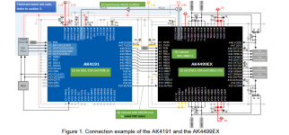
Since I have to solder something and it's not easy, my thoughts fly to the new DAC. I know that I'm embarking on a big project, so I'm starting from scratch, from making a PCB, rectifier, regulator, analog stage, digital inputs. I already have the complete analog stage and power supply solved from previous DACs and that's no problem. The analog stage with tubes is not a problem either.
The problem is which new generation DAC to choose, AKM or ESS, ESS is easier to implement, but I've got my eye on the AKM AK4191 and AK4499EX.
And one more thing bothers me, will this be better than the old school, specifically the eight PCM1702s that I'm playing now?
This question is difficult to answer, I know. To me, the old school sound is somehow more natural and pleasant, closer to analog sources. But I also know that the new generation is often built only according to instructions from DS, I have not seen any sophisticated regulators and analog stages in practice so far.
For sale is a second edition of the Tube Preamp Cookbook. Overall very good shape, it might have a markup or two, but I did not see any with my quick look.
USA shipping only via USPS Padded Envelope. Payment by Zelle or Paypal.
This will be clean sheet build using schematic from Andres, not a modified original ST70. I'll be using 6gm5's in place of 7591's.
I feel pretty confident that substitution.
I plan to evaluate performance similar to steps outlined in article to verify substitutions, once biases and balance settings are achieved.
Design question- Can I use single 6U10 ( 2 low mu, one hi mu triodes) to replace (2) 6sn7 and (1) 12ax7? https://tube-data.com/sheets/123/6/6U10.pdf
Related question- Are interelectrode capacitances important factors to compare when substituting tubes in design? If not, are there other chart characteristics besides Typical, Maximum Voltages and Gain that I should compare?
I'm designing a 3-way passive crossover for my home audio speaker setup and could use some help optimizing the design. My goal is high-fidelity sound with good bass response and smooth integration between drivers.
Driver Selection
Woofer: Dayton Audio DC300-8 (12", 8Ω)
Midrange: Dayton Audio MB620-8 (6", 8Ω)
Tweeter: Eminence ASD1001B compression driver on B-52 PHRN-N01 waveguide (8Ω)
Flat frequency response with smooth phase transitions
Any advice on impedance compensation or phase alignment?
I've attached my XSim schematic and response graphs for reference. Any suggestions or improvements are greatly appreciated!
Hello dear friend this is my first post and Greetings from Sakartvelo i think you are doing great job helping each other also shearing helpful information so I also need your help.
I saw oswaldsmillaudio/monarch series speaker and i fall in love Login to view embedded media so i don`t have 300 000 $ but i must have this speakers at home.
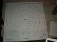
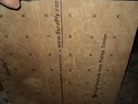
i am good at woodworking and i can build exact same cabinet by myself with custom dimensions, but i could not decide what drivers to use in this build so please help. also my budget is pretty limited max 400$ per speaker (plus minus 50$) also room dimensions for this peace of art is 26 feet X 26 feet X 19 feet (ceiling high ) i know that for 400$ i cant do much to fill this room with crystal clear sound but this design need some good sound, ( also i thought to build World's Second Best Speakers! with pair of full rage tang band w8-1772 speakers and attach wings and design to his built cabinet ) but horn on OMA Monarch speakers should be 3 way horn driver sorry for my English
I did. For years in fact, but put it off thinking there was no way my skill level was up to the task. That is, until our good friend xrk971 opened the door to something that is easy for the layman and very rewarding. See this thread:
There is a lot of info in there but it is a good read. The project I did starts at post #101 but I urge you to read it all as there is some good info throughout and lots of learning as you go along.
Here is a post from member palmiepaul, summarizing the project before even starting to build. It is recommended reading.
It's been a long time since a speaker project has been this fun, rewarding and quick. I admit my hopes were not that high to start, but my mind has changed completely regarding the materials used and the overall effectiveness of the project.
Deeply moving news this afternoon about the cutting down of a timeless and completely defenseless ancient icon.
Thousands have stood here and admired the beauty of this landscape.
If any of you have photos or tangible memories of this place, post them here in memory of this unique tree.
Good morning my friends
I am confuse with a pioneer vsx605s power transformer as the voltage selector switch is distroyed i wanted to bypass and connect just the 120 volts but i do not understand the setup
Hello, Tim here I am into rebuilding crossovers and upgrading capacitors in speakers. I have also built a bunch of powered subwoofer’s. I have an Aleph JZM that sounds amazing.
Han anyone else thought about building a La Scala type enclosure with different dimensions? I have a Joseph Crowe ES600 horn equipped with a SB Audience 65CDN-T compression driver and was planning to build a La Scala type bin but feel the ES600 would out of place with the 24.5 inch (62cm) wide box. So I thought I could maybe build a narrower and taller box keeping the same area for the throat an mouth. What do you think? Stupid idea? 🙂
So I'm working out the final details of my chassis for my Tubelab Simple SE and I figured there are enough Tubelab owners on this board that it might be nice to have some pics of everyone's finished products all in one place. I draw a lot of inspiration from you guys!
So, please post some pics of your Tubelab projects. Finished amps, internal shots, construction pics, etc would all be nice to see.
I have an MF 3.5 amplifier and it it has a serious crackling on the right channel. It bled over to the left a bit but this was fixed by replacing the NE5532 chip on the motorised volume control.
Now it only faults on the right channel. It is a high dc voltage that jumps up and down as I rotate the volume pot. goes from the usual 20 -30mv to 190 + difficult to get it to stay put.
Measuring across the Pre amplifier O/P phonos it is about a 1.3volts.
The caps on the Volume PCB were replaced, and the ceramics tested all OK.
The fault disappears if I disconnect SK5 from the main PCB.
then I can get a 1K tone out of both channels Ok albeit a reduced volume.
So the fault appears to be around the PIC chip perhaps?
All the DC voltages from the regulators are OK and no noise on the rails.
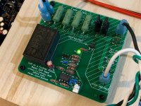
Jhofland and I are pleased to introduce the long-awaited Soft as a Feather Pillow (SFP) solid state relay (SSR) soft start circuit for use with power amplifiers. The development for this circuit has actually been going on for a long time, you will notice that the board design is at v2.1.
The goals of this circuit were to provide a gentle in-rush current limiter using a bank of power resistors during initial turn on, and then having a low Rdson MOSFET bypass the resitors after a set amount of time. By using a SSR vs a mechanical realy, we eliminate a source of arcing and wear, and the switchover is silent - no clacking of relays. Another goal of this circuit was to provide an added benefit of providing an open collector logic signal that can be used in conjunction with a speaker protection SSR that will tell it to instantly shut the speakers off if the voltage rail of the small on-board 5v SMPS turns off.
A special SSR ultra-low Rdson MOSFET was chosen that is rated for 600v, 23A, and has an Rdson of 22mOhms. This SFP can basically soft start almost any power amplifier in DIYA. With a low Rdson value of 44mOhm for two in series, we will have very low dissipation for even higher bias current Class A amplifers. The MOSFET is controlled with the usual opto-coupler and the start on time delay is controlled by a selectable RC circuit and comparator. Variable turn on time delays ranging from 0.5 sec, 1 sec, and 2 seconds is available via a jumper setting.
Here is the schematic:
Edit Mar 3, 2020 revised v2.3 schematic with NTCs instead of resistors:
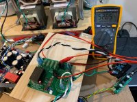
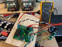
At turn-on, about 52Vac is registered across the four 100ohm (5w ea) wirewound resistors:
2 seconds later, the SSR kicks in and the voltage drops to about 92mVac:
A clamp on current meter showed that the amp was drawing 1.62Arms at the wall plug. So the dissipation across the MOSFETs is only about 150mW. An earlier
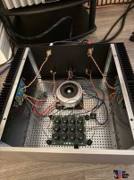
I will continue testing out over the next few days to ensure tha everything works out well.
Edit Dec 17, 2023: including the schematic and BOM to the latest variant called the SFPP (SFP Plus) which includes remote turn on/off with a momentary SPDT switch with LED indicator. Great for low voltage front panel power switches with ring LED.
TLDR; amp is picking up interference from cellular equipment
Last week I picked up a Yaqin MC-10T for a great price and couldn't wait to get my first tube amp into my system. At first listen I was really happy with the way it sounded and settled in to spend some quality time. After about 10 minutes, the right speaker emitted a fairly loud BZT-BZT BZZZZZZZZZT sound, familiar though I haven't heard it in probably 15 years: that noise that GSM phones used to make if they were close to your car radio and about to receive a message. The noise appears like clockwork, every ten minutes. It's not dependent on volume level, or which input is selected. It's in both speakers but one quite a bit louder than the other. I've never heard this before in this room, even with other electronics. I listened to the amp in the previous owner's home for a good 30 minutes with no noise.
I have the schematic; there is nothing in this amp that could possibly be making that noise, nor anything else in the room that I could think of: I unplugged all the electronics in the room, including the DAC and streamer. I unscrewed all the LED smart bulbs. Still the noise continues.
Yesterday the entire country lost power for a day and while waiting for the lights to come back on I decided to move a big ecoflow power station into the room and see, now that NOTHING could possibly be generating RFI, if the amp continued with the noise. It did. What the hell? And then it finally occurred to me: my home has an alarm, and the control panel has a several-day battery backup, and I know there is a SIM card inside because I watched them put it in when they installed the alarm. Clearly it's using the old GSM/GPRS network to communicate with the alarm company, and is phoning home every 10 minutes. This alarm panel is not in my listening room; it's on the other side of a wall about 3M away.
I've tried moving cables around, switched interconnects, put a fancy "hifi" power cable on the amp, oriented the amp a different direction; nothing seems to make a difference. Can anyone offer advice for taming the interference problem? It isn't going to be practical to move the alarm. None of the other gear I've had in the room has had the slightest interference, so I'm guessing I need to look to the amp to solve the problem - is it normal for these amps to be so sensitive to RFI? Or is it possible it's got a fault of some kind?
System: Wiim Pro, Music Hall DAC2.5, Yaquin MC-10T, Dahlquist DQ-28s. AQ Ruby interconnects (tried Evergreens) and Indigo speaker cables.
Well, I somehow managed to build my first solid state amp, based on the TPA3116D2 chip. I used the schematic from the data sheet and it works and sounds great. The power supply is a 130 watt Dell laptop power brick putting out 19.5V. The chip barely gets hot driving 8 ohm speakers. Thanks to everyone who posts here for their ideas and inspiration, especially xrk971 and his great amp, that thread is what pushed me from building a chip amp to a cheaper, high efficiency class D. I scoped the output and the wave is smooth, into a resistive load you can barely see the switching on top of the sine wave. The purpose of the amp is to have something portable to take with me to the garage, basement, etc and it fits the bill quite nicely.
The only problem I ran into was with the output capacitors, I originally had cheap 50V caps in and they quickly smoked without a speaker load. I replaced them with the square 100V caps and all is well. I don't plan on running it without a load but it has to survive at least for a little while if a speaker wire pulls out or isn't connected.
I have an original ST-35 from the 1960s and a Dynakit version I built in 2012. All was going well. The old one is in storage and the Dynakit is the daily use. Upon power up the Dynakit one went quiet. I could see one tube was out. I decided to check out the reason (besides 13 year old tubes). Upon opening it up I see a burnt resistor. I was an early adopter of the EFB modification. I made my own board for it, but I no longer have those plans. The 100 Ohm resistor used across the tube pins 8 and 9 was fried for the dead tube. By the way, I have the 2012 version of the Audio Regenesis PC-13 boards in the amp. This is basically my issue - I can't find the original plans covering the EFB mod, the resistor was fried. I don't remember how to check this thing out or how to set the EFB bias pot.
I bought some new 100 Ohm 0.5W 1% resistors to replace the four used in the original EFB mod at each tube. I turned it back on and the tube is still toast (dimly lit and no heat generation). No sound comes out of either side. I also have a matched set of replacement tubes, but I do not want to put them in if I have another issue. Everything else looks fine visually.
A couple of observations:
I see on the one schematic I found of the old EFB mod that there is a 5 Ohm resistor between pins 3 of the tubes on each side. I see TP on either side of those resistors. I suspect that the bias is to be measured there and then adjusted. I do not have 5 Ohm resistors there, just a wire connecting the two pin 3s. Were the 5 Ohm resistors a temporary install to set bias or were they to remain?
Where else should I troubleshoot? Any help is greatly appreciated - I miss the sound. I am using the 1960s one now, but am a little concerned by its age and lack of use.