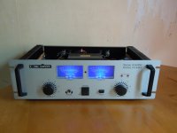
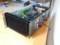
Since I haven't found anything in this forum about this "cheap" PA amplifier, which is very common in Europe, I'll dedicate a separate thread to it, including an explanation and modification suggestions.
First of all: this thing is a stunner, it's very simple, sounds excellent - in my opinion better than the vast majority of analog transistor complementary push-pull products, i.e. almost everything that has been marketed as hi-fi or high-end, regardless of price! Those who measure good sound in kilos (> 14kg) and watts (> 100) are also catered for. Some would have measured 2 x 250 watts into 4 ohms - so here's a tip;-)
I would also advise everyone to try out an existing device first in order to get to know the built up and parts and their sonic effects before attempting big diy projects. So here is a device that costs about 100 euros, can be connected immediately and makes music - within the framework that is commonly interpreted as "high end" - and will be shown some steps that lead to (for many) audible changes.
"However, the transformer is fat! I have 3 meters distance, but after 20 minutes of listening to music I'm exhausted. I will probably remove the transformer and place it 6 meters away;-) This is a general recommendation - to ALL: keep the transformers far away, set up toroidal transformers and point the "hole" towards the listening position (lowest EMF). Many "square" ones have their lowest EMF at the top or bottom, so a steel plate is angled and the transformer is screwed to it tilted. This is occupational safety and health protection! Please also pay attention to your neighbors and children and cats and dogs and budgies and fish and dust mites;-) This is NOT taught in standard electrical training courses"
copied here: https://www.diyaudio.com/community/...e-220-volt-version.368883/page-2#post-7773808
Attachments
And here is the beginner's guide:
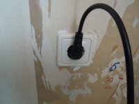
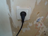
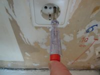
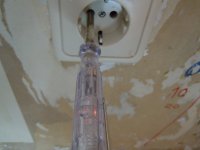
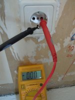
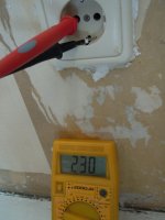
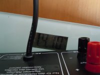
In many European countries, the socket outlet has 3 connections: the earthing visible on the outside, and the actual power conductors. In most cases, only one of these is live, the voltage-free one is the "neutral" conductor. This can be measured using an AC meter or a "phase tester" (e.g. some screwdrivers). And depending on how the device is connected here (2 possible positions of the mains plug), it
a) builds up an electromagnetic field of varying strength (measurable by AC meter - connect between housing and earth, but remove here the earth connection of the device), here 61 VAC wihout power, 122 VAC and 66 VAC with power, and
b) it sounds different.
I leave it up to you to test and listen! The difference should be clearly audible - it corresponds roughly to the comparison between ONE psu and channel separated psu: "dual-mono psu"-)
I also advise to mark the phases on the sockets and plugs.
Attachments
-
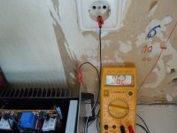 DSCN0570.JPG339.6 KB · Views: 133
 -
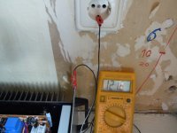 DSCN0571.JPG328.3 KB · Views: 123
 -
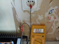 DSCN0572.JPG315.1 KB · Views: 127
 -
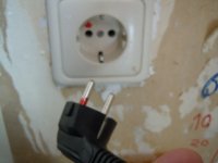 DSCN0573.JPG227.8 KB · Views: 123
 -
 DSCN0569.JPG274.6 KB · Views: 117
 -
 DSCN0568.JPG252.1 KB · Views: 115
 -
 DSCN0567.JPG254.6 KB · Views: 117
 -
 DSCN0566.JPG253.1 KB · Views: 114
 -
 DSCN0565.JPG303.2 KB · Views: 117
 -
 DSCN0564.JPG295.3 KB · Views: 124
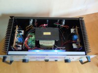
Here is a quick overview of the circuit
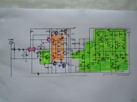
I have copied and marked the circuit:
Preamp: 2 stages, 3 transistors pink,
Power amp 2 stages pp follower: 4 transistors: 2 red positive half-waves, 2 blue negative half-waves,
the green box on the left is the bias control. You can see that the signal for the negative half-wave has to pass through, i.e. it is modulated by a component network - "nonlinear" too. A bypass capacitor with a low cut-off frequency < 20 Hz, which also sounds as neutral and clear as possible, must be used here. If you have such a half-wave unsymmetric pp circuit, you can do the same. Here C7. I replaced with KS-A 220 uF, 6 V meanwhile.
The orange box is a current limiter, which will be removed.
The large green box on the right is the protection circuit and switch-on delay.
I cut out the pure amplifier: fantastically simple circuit;-)
Attachments
I quickly found time to do something:
First of all, I set up the amplifier with 4-fold shielding and grounding so that I, frequency and electro being, can listen for a longer period - and the neighbours too;-)
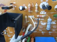
I have removed the current limiter: the sound afterwards is more full-bodied, stripped down, less hiss, less noise, more fluid. These current limiters can also be found in many other Amps: Naim, for example, or Obelisk - I have the 300 (Titan). The same disease - our developers obviously don't even listen to what they are fiddling with!
In the next step C 12, C 14 removed: further de-stressed, the bodyness and contour increase, cleaner.
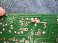
Then R 23 and R 25 are removed, so that the emitter resistors are 0.3 ohm instead of 0.15 ohm: this also sounds more pleasant, the dullness and flatness of the end transistors especially is reduced: the speakers do not get the gray and flat sound impressed on them.
I recommend soldering short wires to the board to avoid bending the legs of the end transistors due to frequent board movement - see picture.
Now the thing is finally in a range that is listenable and really fun: clean gliding through sound images, e.g.:
Attachments
😍
By the way: Today is a wonderful day. I had ordered 5 different pairs of very tough TO-220 transistors for the output of the PA-940 in order to test and to find a pair that plays clearly and cleanly. I also ordered three more NPN types without PNP complementary - you never know if there might be a good one.
I put the first one in and the sun rises. I do think: I've never heard a TO-220 NPN that sooo cool. Then I listened to the others and it only got worse. Then I check my references, and really: I've never had a TO-220 like this before. Outstanding. Something like this can only run as an SE, without any other drivers or supporters - that would only add gray and dirty. A dream! I've ordered a few more. When they arrive and are the same batch, I hope, I'll rebuild the follower to PNP - so that I have to test ca. 50 PNP;-)
A test of 10 transistors means getting up about 40 times and changing and cross-listening. My knees are weak and my legs are weak;-)
This may also be a reference to our hearing memory: it is not just a few seconds, and after all, we have references that we can use;-)
I will tell;-)
I got some transistors in TO-92 for the voltage amplifier to have an alternative sound. These should have a CE voltage of 60 volts - so some could be tried here. The original SC2240s sound very good, about upper mid-range. I would leave these.
I used the BD442 as a second stage. Of course, this is better than the 2SB649.
The BD441/442 can also be used as the driver pair. I don't need to try much here.
But I will start with other small things before I decide on the power transistors.
Last edited:
One thing I also did at the beginning: disconnect one of the two secondary windings of the trafo. To start with, I recommend unsoldering it, then listening to it, soldering it back on, listening to it, and so on until you are sure which sounds better, i.e. cleaner.
If this amplifier had channel-separated power supplies, I would instruct you to connect them, listen, disconnect, listen, reconnect, listen until you know which sounds cleaner;-) But this great device already saves us that;-)
Screwdriver points to one of the two windings, which are here blue cables on the circuit board.
The three steps alone: correct phasing of the mains plug, removal of the current limiters and this secondary winding story elevates the device into a range that shows how open and free it sounds when only about 10 components are working as a SE voltage amplifier and only about 10 components for a push-pull power amplifier. There is not much modulation per parts, the sound is not dense or dark or technical. This is a far from what you can buy - regardless of price;-)
Attachments
I did three little things today while I was waiting for a parcel.
I soldered the output cables directly to the speaker sockets. They originally run via the headphone socket and another jack socket. That robs cleanliness. Nobody needs it. Solder the cables directly to the sockets, not to any solder lugs, which then run over the nuts...-)
Then I bridged the pots. I replaced the first one with a 100 kOhm. Simply run the input cable directly from the input sockets to the amplifier board. This also brings a lot of cleanliness, silence and shine.
I have replaced the bias transistor, Q3. Use the best-sounding, cleanest one you have. Even those with tomatoes in their ears do hear the difference;-)
By the way: these thin tin RCA sockets sound finer and wider than the vast majority of thick gold-plated Cicnh sockets. These only make crash. However, there is a fine veil in the sound with the thin things.
Attachments
My repeat order of some ot the magic TO-220, #8, arrived today. And look, there's a transistor from a different batch: it sounds narrower, duller, more colorless, less bright. The magic is over)-;
I think it should be clear why complementary transistors pp concepts have no place in audio.
And without determining the sound characteristics of the respective parts, a condition for audio, hi-fi, even "high-end", is not fulfilled.
I think it should be clear why complementary transistors pp concepts have no place in audio.
And without determining the sound characteristics of the respective parts, a condition for audio, hi-fi, even "high-end", is not fulfilled.
The magic would have been over when the magic smoke got released anyway. TO-220 bipolars aren’t going to take +/-50V operation for very long, regardless of how good or bad it sounds.
This device also disproves this claim: the drivers are TO-220 and are connected to a CE voltage of +/-50V.
You must talk about < 50 V types;-)
Forgotten, we all miss the mark from time to time. By the way: only through contrasts like these do we experience and learn, develop images of ourselves and the world;-)
I have done a little more to it:
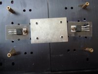
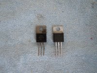
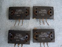
- I have installed a pair of BD909/BD910 for the time being. The original, 2SA1215, 2SC2921, fat MT-200-casings sound terrible, regardless of whether Sanken is only written on or is also inside. The sound is, despite the definitely different sounding BDs (see photo), equally raven-black, liquid, the bass rolls, the bass-drum stands with contour in the room shown, the instruments virtually shine. The sound seems a little smaller at first, but this is due to the greater cleanliness, the lack of hiss and the absence of noise.
All that remains now is to remove unnecessary transitions, such as soldering lugs, and to replace the original wires with single-core copper cables - I use diameter 0.8 mm for this device. And later a look at the diodes and electrolytic capacitors. That's all you need to do to get the tears rolling with clarity, groove, tempo and fluidity: 1A home audio amp;-)
If you want a little more width and relaxation, and also a higher load potential for long, loud events, you should use two BDs in parallel.
You must talk about < 50 V types;-)
Forgotten, we all miss the mark from time to time. By the way: only through contrasts like these do we experience and learn, develop images of ourselves and the world;-)
I have done a little more to it:
- I had put in other ceramic load resistors, but these original ones sound a bit better. I also want to point out film resistors in TO-220 or even TO-126 housings, these sound much cleaner than the ceramic types.
- The ground connection amplifier - power supply is located at the lower end of the amplifier board, at the protective circuit. I have raised this to the amplifier ground area.
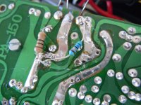
- If you have the time, you can solder out your resistors and make the most direct connections. This saves signal path and also unnecessary connections, bends and turns. This is academic in itself, but adds up to a cleaner and more homogeneous sound. If you want, you can also solder in new resistors with the right lengths. Roughly speaking: carbon layers sound a little quieter, metal layers a little brighter and more restless.
- I have installed a pair of BD909/BD910 for the time being. The original, 2SA1215, 2SC2921, fat MT-200-casings sound terrible, regardless of whether Sanken is only written on or is also inside. The sound is, despite the definitely different sounding BDs (see photo), equally raven-black, liquid, the bass rolls, the bass-drum stands with contour in the room shown, the instruments virtually shine. The sound seems a little smaller at first, but this is due to the greater cleanliness, the lack of hiss and the absence of noise.
All that remains now is to remove unnecessary transitions, such as soldering lugs, and to replace the original wires with single-core copper cables - I use diameter 0.8 mm for this device. And later a look at the diodes and electrolytic capacitors. That's all you need to do to get the tears rolling with clarity, groove, tempo and fluidity: 1A home audio amp;-)
If you want a little more width and relaxation, and also a higher load potential for long, loud events, you should use two BDs in parallel.
Attachments
Last edited:
One pair of BD909/10 isn’t going to take this very long. It might be ok playing background music levels for a while. But not make it much past a 90 day warranty period. Parallel two or three and you might be getting back to the reliability levels of regular audio output types, but the capacitances will climb back up to the same levels and everything is right back where you started.
Two or three TO-220s in parallel sound MUCH better than one MT-200. I demand a little more audio experience after 20 years diy audio!
My guess is you’re fooling yourself. It happens more often than not when comparing only by listening. Just looking the circuit over, I’d say that it wouldn’t SOUND any different regardless of what types were stuck in there, provided the bias is set to the same current. If say three pair of 3 MHz old school epi-base types do sound or even measure better (or even as good) as a single pair of LAPTs then the original circuit was either not competently designed - or does NOT take advantage of their capabilities. It may NOT sound any better with 20 MHz outputs, regardless of case size. 20 MHz TO-220’s like MJE15031 would go up in the biggest ball of fire since the last sun in these parts exploded. Try it and see, I DARE you. Take lots of pictures. The original intent of this type of amplifier is as a “beater” and the only thing that might have mattered is how strong a single output pair was. Three pairs of outputs adds significant assembly costs, and so does installing very robust TO-3’s like the MJ15024. So you end up with MT200’s.
Continue with audio: just replaced: the channel and half-wave unequal cables. Ensure equal lengths when rewiring.
I removed the speaker ground connections from the power supply unit and connected them to the amplifier boards. This also sounds more de-stressed.
I removed the speaker ground connections from the power supply unit and connected them to the amplifier boards. This also sounds more de-stressed.
Attachments
After what I heard today - I only have a pair 15 cm full range driver - even my jaw dropped - a fundament, endless pressure and highly resolved and contoured: e.g. Jeff Beck here sounded as if the instrument amplifiers were in the room, and the bass drum... 😍 but the Spanish wall typical of complementary transistors PP is to hear! The body imaging and homogeneity was not clean, especially in the vocal range and treble - I'll try the small BD441/442;-) As always: listen first and see what works;-)
I am thinking about how I can detect transistors, which are somewhat complementary in sound! in the simplest possible way;-)
I am thinking about how I can detect transistors, which are somewhat complementary in sound! in the simplest possible way;-)
- Home
- Amplifiers
- Solid State
- PA-940 - Mc Crypt, Better, Sun Key, Stage Audio, JB Systems...
![DSCN0583[1].JPG](/community/data/attachments/1258/1258790-dc24147a03a2bbe6456d8cbf5728ca22.jpg?hash=3CQUegOiu-)
![DSCN0584[1].JPG](/community/data/attachments/1259/1259229-53814148605790fb95400529990c9af4.jpg?hash=U4FBSGBXkP)
![DSCN0585[1].JPG](/community/data/attachments/1259/1259230-5bc07ac1c97b336ec52d574cb1aed001.jpg?hash=W8B6wcl7M2)
![DSCN0586[1].JPG](/community/data/attachments/1259/1259231-0b0660ecae019bc3ef4f337065b0737d.jpg?hash=CwZg7K4Bm8)
![DSCN0588[1].JPG](/community/data/attachments/1259/1259232-2b595652b29b741362a9350b699fb293.jpg?hash=K1lWUrKbdB)
![DSCN0587[1].JPG](/community/data/attachments/1259/1259233-daa8aa1160d7a6499ac94083af3d6395.jpg?hash=2qiqEWDXpk)
![DSCN0575[1].JPG](/community/data/attachments/1260/1260915-48f2bcc456e2d234586b25d4311cdb4b.jpg?hash=SPK8xFbi0j)
![DSCN0593[1].JPG](/community/data/attachments/1261/1261014-709ae4204a317426281903496e456c96.jpg?hash=cJrkIEoxdC)
![DSCN0594[1].JPG](/community/data/attachments/1261/1261013-7ba18f32ad09be2352874c466a89646a.jpg?hash=e6GPMq0Jvi)

![DSCN0602[1].JPG](/community/data/attachments/1262/1262201-6bb642dd8758c6ee0a7878e5613b409f.jpg?hash=a7ZC3YdYxu)