VCAs instead of POTs

When I first tried to create an audio amp as a keen electronics newbie I just couldn't accept that you throw away almost the entirety of the dynamic range and then gain it X fold. Lifting the noise floor with that gain. I mean the prevalence of input potentiometers preceding gain stages. Mostly they seem to be stereo pots as well, introducing oppurtunities for imbalance, cross talk and "track noise".

One of the first first PCBs I got printed was a stereo baxandal pre-amp with -something db and +20db. Active gain control rather than attenuate and boost taking the noise up with you.

VCA I understand to mean "voltage controller amplifier" and I'm assuming an IC style component that will given an input/output and a voltage signal as to how much to gain it, this "active volume control/gain stage" can be encapsulated in IC land.

In the digital world of course sending a binary 8/16bit would be preferred. However I'll take an analogue voltage control if I have to.

Consider if you digitally process a stream and for whatever reason you drop the "gain" by a factor of 2. The other way you can do that is by shortening the bit width by 1. Dropping "half" the dynamic range. A contrived example is a 5 to 1 mix down stage. You could be tempted to mix E=[signalN/5] but you just cut the dynamic range of all inputs by a factor 5.

How do you do a lossless gain stage? I suppose the answer that jumps out at me from analogue mixing desks best practices is... don't. Try to keep the faders and gain knobs as close to 0db as you can get away with. Flat gain structure to the output stage as much as possible.

Sorry if this post seems odd, I spend a lot of time handling audio as a stream or arrays of numbers and lowering everything by a factor only to indiscrimately gain it a fix amount is like doing: int sample = (sample << 8) >> 8; which is literally a loss in precision of 8 bits.

Am I missing something?

New build: 6F12P - 6N8S - 6P36S triode push pull.

I decided to scrap amp 2 and build it with SS rectification... Layout real estate says I have to mount that cap 2mm from the heater transformer... Hopefully it won't be a hum magnet.

Coils are all Hammond. 278CX for PT, 1650N for OPT, 193Q for reactor, 155J for filtering/smoothing for VA/PI/Driver, and 167V12 for heater supply. Glad I didn't buy them from Digikey. BOM is almost 1000$ CAD for just the coils and chassis parts! If you're in the GTA and want anything Hammond, see Glen at A1 electronic parts... 196 North Queen. index

Any comments?

Attachments

  • 6F12P-12SN7-6P36S.svg.png
    6F12P-12SN7-6P36S.svg.png
    361.1 KB · Views: 1,004
  • 2019-09-06 17-56-36.jpg
    2019-09-06 17-56-36.jpg
    1,014.8 KB · Views: 885
  • 2019-09-06 17-57-00.jpg
    2019-09-06 17-57-00.jpg
    956.8 KB · Views: 913

Modular Amplifier 1.

Hey all!

After a long time in testing and development, I present the Modular Amplifier 1.

It uses a 6F12P as VA/PI, and 6N8S or 6SN7 (12SN7) as driver, and your choice of over 100 different triode connected tubes for PP output. Beam/Pentode/Tetrode or UL can be achieved by connecting only one side of the screen resistor, too (the other side being connected to the screen supply/UL tap accordingly).

The tube list is as follows:

Code:
MA-1 6CK Octal - 12AV5 17AV5 18A5 25AV5 6000 6AU5 6AV5 6DB5 6FW5
MA-1 9NH Magnoval - 6P36S 13GB5 18GB5 27GB5 28GB5 6GB5 EL500 EL504 PL500 PL504 6P44S
MA-1 7AC/8GT Octal - 7AC BASE: 12A6 12EF6 12EN6 12L6 12V6 12W6 1614 1621 1622 1631 1632 17L6 17W6 25A6 25B6 25C6 25L6 25W6 26E6 26L6 35L6 36L6 50C6 50L6 50L7 5824 5871 5881 5932 5992 5V6 6046 6550 6AG6 6AY5 6DG6 6EF6 6EY6 6EZ5 6F6 6G6 6K6 6L6 6P6S 6P3S 6U6 6V6 6W6 6Y6 7184 7408 7581 7EY6 8417 9EF6 EL33 EL35 EL37 KT32 KT61 KT63 KT66 KT67 KT71 KT76 KT77 KT88 KT120 KT150 PL33) 8GT BASE: 25E5 25GF6 30P19 30P4 6CM5 6P31S EL36 PL36 TT21 TT22
MA-1 9RJ Magnoval - 40KG6 6KG6 EL509 EL519 PL509 PL519 6P45S
MA-1 9RW Magnoval - 7868 6P41S
MA-1 8BD Octal - 10EG7 10EM7 12SL7 12SN7 12SX7 13D2 13EM7 15EA7 1633 2C50 2C52 5691 5692 5998 6080 6082 6113 6188 6336 6394 6520 6528 6AS7 6BL7 6BX7 6DN7 6EA7 6EM7 6GL7 6N8S 6N9S 6SL7 6SN7 6SU7 7105 7236 7802 7C5 8SN7ECC32 ECC33 ECC34 ECC35 ECC230
MA-1 12BJ Compactron - 6GE5 12GE5 17GE5
MA-1 9CV Noval - 10BQ5 10P18 15CW5 16A5 30P16 30P18 45B5 6BQ5 6CW5 6P15P 6P43P 7189 7320 EL84 EL86 PL82 PL84 UL84
MA-1 12ES Compactron - 6HD5
MA-1 9NZ Novar  - 6GT5 12GT5 17GT5
MA-1 9QU Novar - 6KV6 17KV6 22KV6
MA-1 12FY Compactron - 6LR6 36LR6
MA-1 8JC Octal - 6DQ5
MA-1 LW6 Octal - 6LW6 26LW6 36LW6

Modular because each of the above output boards share the same footprint and so are swappable.

The amplifier is designed to run from a voltage doubler/quadrupler from 120V (or single/double on 230V) using an isolation xfmr, and the output can use my interleaved Triad PT as OPT method.

The result is an amplifier varying from 10WPC to 80WPC depending on tubes and iron choices.

PCBs are available. Schematic attached. The VA/PI now use two 100uF/400V caps in series instead of the 47u/600V in the schematic due to availability and cost.
Pictured: 6P36S output and 6P45S output, and 12GE5 output.
6P36S is using a 250VA PT and pairs of 100VA for OPT. 80mA idle
6P45S is using a 625VA PT and pairs of 250VA for OPT. 100mA idle
12GE5 is using a 300VA PT and pairs of 100VA for OPT. 60mA idle (Sold)

Some power numbers (I will update as I continue to run more tests). All tests done with B+ of 320-340V with a 2k2 load unless otherwise specified, 1 kHz sine driving to the point of clipping and backed off 1/10th volt input, triode connection (* audio tubes need higher plate voltage and higher Z loading than sweep tubes):
6DQ6GTB: 24WRMS
6P31S: 37WRMS
6P45S: 113WRMS (1k3 load, 30Hz, 2 tubes parallel)
*EL34: 12WRMS
*KT88/6550: 15WRMS
*6P3S: 6WRMS
12AV5/12GE5/12GT5: 24WRMS

Attachments

  • PSU-dbl-quad.png
    PSU-dbl-quad.png
    63.4 KB · Views: 1,231
  • 2021-07-30 17-31-51.jpg
    2021-07-30 17-31-51.jpg
    855.4 KB · Views: 1,014
  • 2021-07-30 17-48-22.jpg
    2021-07-30 17-48-22.jpg
    904.6 KB · Views: 856
  • 2021-07-13 15-09-31.jpg
    2021-07-13 15-09-31.jpg
    928.9 KB · Views: 1,010
  • 12AV5GA-MA-1.png
    12AV5GA-MA-1.png
    29.8 KB · Views: 715
  • Like
Reactions: ziffel and JMFahey

I'm having 19vdc at my surround speaker outputs, yet the subwoofer output is okay, my speakers even got burnt.

I made a tda2030 subwoofer 2.1 amp, but at first everything seemed to move on well, but as time went, i started smelling burning smoke from my surround speakers, i disconnected them, and when i tested with a multimeter, i got 19vdc at the outputs, am using 14vac dual transformer, yet if i switch the whole set up on, the sub speaker working normally, so please help me

Rewiring a Leslie 125 amp into what?

Hey, guys. I haven't posted to this site in 10 years or so! Good to be back! 🙂

So, i'm looking for advice, both opinion and technical...

I have a Leslie 125 amplifier that's not in use. I'd like to make my first guitar amp project out of it. ( i've rebuilt / repaired a dozen amps at this point, so i'm not a total newb ). I'm bouncing around between what it would turn readily into, that's worth building. I'm thinking something like a Fender Tweed Deluxe or Bassman.

Here's the schematic of the amp http://www.hammondb3organ.net/schematics/leslie/125/125.gif

It's supposedly 20 watts, but what i don't get is why it's only 20 watts, when it seems like it could do more based on the components. Don't 2x 6L6GC amps put out 45-60 watts, depending on how they are wired? I've read that this amp makes a nice tweed deluxe, but the Tweed Deluxe uses 2x 6V6, and this amp seems capable of more... but i don't want to burn out the transformers by turning it into a tweed bassman when it's not capable of it.

Also, the leslie is solid state rectified, and the old tweeds were all tube rectified ( and i see no 5v taps on the trafo, so i guess i'll be sticking with SS).

Any opinions?

M-Audio SuperDAC 2496 - Fun, Simple Modifications

Hi All

First post, please be gentle with me etc.

I've recently moved house and, hence, have the luxury of unpacking some long-archived bits of audio kit.

One of them is the forum favourite of a couple of decades ago, the M-Audio SuperDAC 2496.

So, I've got to say, it doesn't sound half bad, and I've compared it to several more modern bits of kit.

I've already replaced the 1/4 inch jacks with RCAs so it's very easy to connect up and cable-swap.

However, ever the one to attempt low risk / low cost tinkering, does anybody have tips on:

1. A 12V AC power supply that I can buy in the UK, and if that makes a difference.

2. If the AKM DAC chip can be swapped out simply or is soldered in place.

Any other cheap, fun things I can do to it to have a bit of fun.

Cheers and Happy Friday

BDD

Open baffle design, 2.5-way

Hi,

I’m planning my first DIY sound system. I’ve read what I could reasonably absorb over a couple of months of afterwork readings, and all things considered I think I’ll go for an OB design, with 2x12” woofers, and one tweeter. Closer designs are Manzanita, Spatial Audio project M4…

Shortlisted drivers, based on basic criteria within my reach, are the Ciare FXI12.50W (https://www.audiovideoparts.com/disegni/FXI12.50W.pdf) and the SS DISCOVERY D2608/91300 (https://www.scan-speak.dk/product/d2608-913000/). I don’t really know how to make sure these two are a good fit apart from a good overlap of the SPL/Frequency SIM charts, which I think is ok. I’m open to suggestions, possibly made in EU, where I will buy them. Some questions:

  • Should I push more the analysis of drivers before purchasing or, as I read somewhere, the only way is to buy and check for yourself?
  • Can the two woofers be wired in series and so be treated as one by the minidsp/amp?
My idea is to have a music server – minidsp flex – 2 amps class D hypex NC122MP with 4 output channels total.
  • Would it be feasible, and a significant improvement, to put a passive crossover low pass filter for one of the two woofers (I’ve seen standalone components for that) not to exceed the total 4 channels planned?
  • If the tweeter has 8 ohm impedance, does it matter whether the woofers are 4 or 8 ohm?
  • In alternative to the 2.5 way system a.m., would it make more, from a sound perspective, to have 2-way main loudpeakers and add an active subwoofer?
No point in describing the listening room as I have to move every few years for work (approx 5x10m right now).

Any insight would be highly appreciated.

David

ADS PQ10 Power Supply Problems

Seems like my PQ10's power supply is broken. Positive rail is moving around 12v and the negative at around -2.5v.

I've never had a need to understand how a car amplifier's PS works, so I took the opportunity to do some reading. Pretty fascinating.

Nothing looks burned out. Nothing looks abused.

I really don't understand the circuit to turn Q801-4 on and off. I don't understand why the circuit on Q801/2 Base is so much different than Q803/4, I thought they'd be the same. (Schematic attached.)

Here are some measurements using 12.1vdc power to the amp:
Q801-4 (all four measure the same)
B=13.1v (erratic) And wouldn't C806 block the dc to the base on Q803 and 4?
C=0v
E=12.1v
Each Base measures around 30 hertz (erratic). I thought this would be well out of the audible range, like 50-100 kHz.

I don't measure any AC on the rectifier diodes (CR807 and CR808). I get -2.7vdc (erratic) out of CR807, and 12vdc (erratic) out of CR808. I also get 2.4vdc to ground on each rectifier on what I expect is the AC connections from the transformer.

I'll check around for a local repair shop, but thought I'd throw it out here first.

BTW, all measurements with a multimeter, no oscilloscope.

Thanks,
Dan

IMG_2409.JPG

Attachments

  • ads pq10 schematic.jpeg
    ads pq10 schematic.jpeg
    240.9 KB · Views: 211

SBacoustics + slit cone (poor man's revelator)?

Hello!
Has anyone attempted slicing of the SB midwoofers?

Since SBacoustics line and Revelator line have been designed by same designer (U.S.), SS or VIFA still own NRSC patent. (Non resonant *slit cone*)

Anyway, lots of googling revealed that the revelator designer (USXX) did a prototype design on the SB15:
JF_HT_bas1.jpg

full link:
Julefrokosthojttalere - SpeakerBuilder Forum - Page 1


SB and SS motors are similar (esp. SD motor in SS Classic line) (THanks to Mr. Pankov for teardown)
13m8640_basket_motor_angled.jpg

689121d1530127894-sb-acoustics-midwoofer-teardown-20180627_214915-jpg


Distortion plots (from audioexcite):
SB:
SB15NRXC30-4-1L-15cm-90db.jpg

SS:
15W-4531G00-2R-18cm-90db.jpg


Other measurements are available at HIFICOMPASS.

Imho motor should be as good as revelator - check out aluminum or ceramic cone measurements, with the same motor. According to USXX, MFC(poly driver) had some changes to surround, carbon/rohacell has even better spider... (Haven't heard any of the sb woofers, other than Satori.)

Okay, then someone did the same slicing thing to their Dayton PM180:
How to Train Your PM180-8 -

Techtalk Speaker Building, Audio, Video Discussion Forum
- impressive results!

Then i was thinking about which slicing pattern to use? Something random, or triangle as did Ulrich with his prototype? Hmm, guess it was in front of me all the time (datasheet)!
imgrc0067621028.jpg


Other thing was how to glue it together... a bit of googling revealed a wallpaper glue could be used! Also, I'd coat the surround with the same glue to try to remove some of the dip.

Anyways, new sb17nrx2c measurement is more linear and should be a perfect candidate for a rev surgery at one third of the price. (Thanks to Goran for testing) www.audioexcite.com >> Blog Archive >> SB17NRX2C35-4 vs SB17NRXC35-4

Personally I'm more interested in SB15 line because cone geometry looks to be very nice - check how SB15MFC (poly cone) has a nice even off-axis dispersion, without any serious breakups and phase problems. Rising response just means a bit more work in the xo.
An externally hosted image should be here but it was not working when we last tested it.


I'm wondering if I should get Norex/papyrus cone instead, and attempt the surgery. OTOH, can anyone compare norex to poly soundwise, just a general impression?

Linkplay: possible to combine A31 & A98 from different brands?

Intro
I want to build a wireless audio streaming setup, that supports Google Assistant for voice commands. I want to be able to start/pause/stop an audio stream/listening to music, by voice commands.

I have built a lot of systems already using the Linkplay A31 (v04) module, embedded into someones manufactured board. This A31 module does not support Google Assistant, but the Linkplay A98 does.

Questions
  1. Would it be possible to combine the Linkplay A31 implemented in the product by Arylic, with the Linkplay A98 implemented by CloudYX, and use them combined/grouped within the same wireless streaming system?
  2. Would it be possible for both to be managed by the 4Stream App?
  3. Would it be possible in this setup, to use the device with the Linkplay A98 to handle the Google Voice Commands, and start/pause/stop playing music on the the other device with the Linkplay A31?


References

Linkplay A31 by Arylic:
1673605730253.png


Linkplay A98 by CloudYX:
1673605762723.png

4Stream App:

1673605785419.png

The 40 year old software bug

Around 40 years ago I wrote a screen driver for a 1602 LCD display.
It has worked well in many projects.

Until today when I bought in a blue 1602 display off ebay.
While I could write to line 1 writing to line 2 only displayed first character.
I tried various addresses for line 2 start but nothing worked.
So into the driver going through every set up instruction.
I then noticed the start of line 2 is 0x40 hex where as I had been using 40 which had previously worked.
Even setting line 2 start to 0x40 didnt work.
So back into the code.
I then noticed the set cursor position has highest bit set to denote set cursor position command and rest of bits are actual position.
I then spotted my mistake, I was anding new cursor position with 0x3f when it should ne 0x7f.
This was clipping the highest address I could send for cursor position.
So changed it to 0x7f and then everything worked fine.

So while 40 worked it really shouldn't have. It worked with many displays I have used over the years.
Never too old to learn from mistakes.

Opamp preamp with transistor input stage noise

Hi

I have built this bass guitar preamp (the schematic is pretty large so i'm showing the section where some help would be welcome). It is mainly opamp based but the input section is transistor, with 2x 2N5457, genuine transistors bought from Mouser. The whole thing works overall, but the input discrete section is giving out some noise which is pretty audible. I have decided to use the input transsitor stage as i found it online as recommended as a good guitar preamp with plenty of gain, and it does work like that but with some extra noise in this case.

I'm supplying 15V to the transistor section, same power line as the positive for the opamps. I'm using step up voltage converter that bumps up from normal 9V to symmetrical 15V.

This is what i have discovered so far:

  • Volume pot all the down/off or I remove the "A-Signal" which is a jumper to separate the discrete audio line from the opamp section, there is no noise at all, just the very minimal normal noise from the circuit after the pot. Meaning the extra noise comes from the transistor section, the opamp section is dead quiet.
  • With the VR2 and VR3 set to about 10k, the noise is pretty audible in the upper mid and high range. When the Trim pot, VR1, is being turned it is creating some light crackling noise and the noise level varies a little as you turn. Have tried different pots with same results.
  • Just to experiment, have set the VR3 to about 1.5-1.1k or so, the overall gain is lower than i need but the noise is completely gone, but ONLY when the Trim pot is full clockwise. In this case, turning the Trim pot counter clockwise brings some of the noise back, but crackling is gone when turning it (the noise level is the same at any setting/resistance of the Trim pot though) except when is full clockwise where there is no noise as i mentioned. Only then the circuit sounds like it should sound at any setting. Adjusting VR2 doesn't affect the noise, just the gain of the input transistor.

What am i missing here?

preamp input section.png

2way with Viawave GRT-145/4 + Purifi PTT6.5X04-NFA-01

Hi there,

this is my first post here, so a little bit about myself first:

Got into "hifi" via headphones around 2002 (still there), did some DIY-Headphone amps
and ended up designing DIY-speakers 😎 Going active since MiniDSPs were already there...

I'm here to show my work and hopefully get some input to improve my work 🙂

This is my third design from scratch, the purify woofers tempted me and
I got my hands on a pair of nice "finished" speakers that the previous owner built
but never finished the crossover.

That's what they look like:

PXL_20221110_203713590.jpg


Driven by MiniDSP DDRC24 and IcePower 50ASX2 / 125ASX2

Here's my measurement setup:

WhatsApp Image 2022-05-06 at 09.44.00.jpeg


Raw measurements:

viawave measurements.jpg


Woofer measurements.jpg


nearfield.jpg


For crossover developement and simulation I use VituixCAD.

Here's my latest iteration:

2.3.jpg


I'm not completely happy atm since they're still sounding a bit "bright" listening to Heavy Metal (what I mostly do 🤘).


So much for today - any comment / hint / question is welcome!

  • Locked
Power Conditioners and Cords

Hello All

The utility of power conditioners and cords is well established, particularly for those living in cities or in industrial areas, but it is more difficult, at least for me, to make a case for that utility for those living in rural areas. I am wondering if there are any evaluations a DIYer can conduct that would indicate the need for such equipment?

Cheers,

ceulrich

Sigma 22 clone for 3 x LM3886 clone amp. Total Novice with ideas way about his abilities need help.

To put in bluntly I have been scared to post as I am a complete novice. I tried to send a PM to someone who appeared nice, but I could not find a way. So I am putting caution aside.

To keep me amused and my mental health intact, during my final divorce settlement, as we are selling house, I decided to start a project and got 3 fully assembled boards:

2 x LN3886 x 3 mono board – that I have now lost

1 x Sigma 22 Zero Zone clone configured for 35VDC

Plan to get toroidal 33V – but even that is confusing.

My plan was 2 x mono blocs and hence I under ordered the PSU.

Also soft start and speaker protectors, but they seem quite easy…I think

I have been looking for days for a hook up diagram. I cannot find a schematic of the board that shows inputs and outputs. The components obscure the writing and when I found a board it was not helpful.

Many of the Chinese sellers have diagrams…this goes to this. But I have drawn a blank. Can you assist?

Any suggestions?? Hypex suits my skill level, but not my budget. The lost amps, has sort of thrown my plan off course.

If you do can you point me in a direction to get the diagram. I am a total novice, I can follow instructions, but that is it.


Regard

Dan

foxint@foxint.com.au

Attachments

  • 2pcs x LM3886-325426791430.jpg
    2pcs x LM3886-325426791430.jpg
    29.3 KB · Views: 130
  • Sigma22-005.jpg
    Sigma22-005.jpg
    78.2 KB · Views: 144
  • Sigma22-004.jpg
    Sigma22-004.jpg
    105.7 KB · Views: 136

Vintage 3 prong connector

Does anyone know what this chassis plug is? It's mid 60s vintage and is the tape input on an RCA console stereo. Left/right with ground in the center. It's maybe 25-30mm wide.

I vaguely remember these connectors, but haven't seen one in agesand sure don't know what it's called.
Of course the irony is that this RCA console has no RCA connectors. 😛

Multiple earth connections?

I have a metal chassis that’s anodizied. I connected bottom plate within the chassis to the main earth point, and it works fine. But testing the various side panels with a meter and what not, they don’t seem to be connected. I’m guessing the anodizing on the panels interferes with the connection in some spots.

Is there any harm from using the earth lug as a star point for earth and running and few wires to the other chassis panels to ensure they are properly earthed as well? From a safety perspective I’d be more comfortable if any panel a user might touch would be properly earthed.

Help please to identify switch type

Hoping one of the experts here can tell me the name of the switch mechanism I'm looking to replace. It's on a Pioneer A-656 amp, but I've seen them elsewhere.

At the user end it is a rotary 5-way mechanism, and behind the front panel, the mechanism converts this to a linear motion which, by means of a metal connector, operates a slider switch mounted on a pcb.

I'm sure there must be a simple name for this but can't seem to find it. Then starts the hunt for a replacement!

Many thanks.

My name is Patrick and I need you

hello I'm new in this forum.. Let me introduce myself, my name is Patrizio I live near Rome (Italy), forgive me if I use goole translator, I don't speak English well. I have been building amplifiers and other electronics for years but only as a hobby. I got a lot of advice from this forum. But I need to keep in touch with people like me. So in the next posts I will ask you for your opinion on the work I'm doing and some advice and also some diagrams of some electronics that I try to repair that are difficult to find for a hobbyist like me. I hope I'm not in the wrong section.

12AX7 wiring suggestions

Hi All,
My first post here.

I recently build an 12AX7 tube preamp, got it working quite well. I am very pleased with the sound of it.

Did the star grounding and all cabling is done properly. I run the tubes at 250VDC.

I have one question though, I want to wire the Noval sockets to be chassis mount, so I got sockets and I tried to wire the sockets with wires (around 15cm) and got hum and buzz, although the proper pin connections were made, wires are 0.5mm sq.

Is there any specific way to wire / group wires in order to cancel the hum?

Regards,
Matyin

Question about Behringer A800, one channel louder.

I'm running my setup using two a800s and mini dsp balanced. I bought these amps almost two years ago. was not listening to it for almost 1,5 years.

now i remembered that I found the levels on the amps to be not exact, one channel in one amp was louder. I've set it to different level and called it a day. but since i can still use warranty, is there any way to reliably check the level of channel output with multimeter? can someone help me?

Darlington Question

I have an amp I'm working on with some strange problems.

There is a section of the amp with a darlington transistor, TIP142, that has a diode in parallel with a resistor on the emitter. I've not seen this type of design and I'm trying to understand the purpose and operation of that section of the amp.

I have attached a snippet of the schema showing this arrangement. With the resistor in parallel, it's not really preventing current from flowing the opposite direction. On the forward direction, it seems like it would prevent any voltage larger than ~0.6v across the resistor as above that the diode would effectively short out the resistor.

Any help understanding the operation of this would be appreciated.

Darlington.JPG

Manufacturers Contradiction

I recently purchased Technics SA-5570 and have slowly been bringing it back up to par. Today both fuses on the back of the unit blew and after further inspection, I found out they were only 1A and on the back of the unit it clearly states 4.0A 250V. Well I remember I recently came across this in the service manual and recall seeing 5A for the speaker fuses. I've included pictures of the manufacturers little contradiction. Now the real question is what fuse should I put in there?

Attachments

  • 20230112_155620.jpg
    20230112_155620.jpg
    547.8 KB · Views: 95
  • Screenshot_20230112_175027.jpg
    Screenshot_20230112_175027.jpg
    124.7 KB · Views: 91

Resistor Value for Diode

Hi,

I am trying to calculate the resistor value for this diode in attachment, but the calculation gives result in hundreds not in thousand ohms...
I am trying to build a Aleph J and my transfo will gives 20 V. The BOM says the R should be between 3K and 5K so i am puzzled...
any help please ?

Attachments

Parts list for Indigo bash powered amplifier pcb 600141 klipsch 12 inch subwoofer model number sub 12 hg

I have a klipsch synergy 12 inch powered subwoofer that I blew R72 and R73 on the main pcb and can't find a parts list to find out what they are to replace them please someone help me

Attachments

  • 600141-A_SS - sub12.pdf
    600141-A_SS - sub12.pdf
    76.7 KB · Views: 161
  • Screenshot_20230112-164316_Drive.jpg
    Screenshot_20230112-164316_Drive.jpg
    148.9 KB · Views: 188
  • Screenshot_20230112-164349_Drive.jpg
    Screenshot_20230112-164349_Drive.jpg
    44.3 KB · Views: 197
  • Screenshot_20230112-164346_Drive.jpg
    Screenshot_20230112-164346_Drive.jpg
    132.8 KB · Views: 252
  • Screenshot_20230112-164313_Drive.jpg
    Screenshot_20230112-164313_Drive.jpg
    133.7 KB · Views: 198

Anyone toyed with the idea of GFRC glass-fiber-reinforced-concrete for baffles?

I see no real obstacles. GFRC is designed for much lower weight and strong thin-section areas such as between woofers and the uprights next to the woofers. It can be solid tinted. It is ready to be unmolded within 24hrs. The mold itself requires basic woodworking skills and makes countersinking woofers and experimenting with waveguides a relative breeze. Countersinking, for instance, is a matter of jigsawing and gluing up pieces in the mold as opposed to intricate work with a router bit, especially if you wish to very cleanly countersink an oddly shaped flange. Waveguides are a matter of plaster casting a negative using any available model (off-the-shelf waveguide) and positioning it in your mold. I'm a complete novice. But the GFRC tutorials online for countertops, which are remarkably similar to speaker baffles, do not describe it as being that daunting.

jpg for diyaudio.jpg
  • Like
Reactions: Haze Head

Looking for fast (ft) TO220 similar to 2SA1930/2SC5171

Hello all, I’m hoping to get your help. I’m looking for an NPN/PNP pair that are similar in spec to the 2SA1930 and 2SC5171. They’re spec’d with an ft of 200 MHz, but anything close would be nice. 175, 150, 120…

I did a look and came up with 2SC6082 and 2SA2210, but the voltage (Vce and Vcb) are too low. I’m replacing a faulty pair of driver (2SA913 and 2SC1913) with a ft of 120 MHz and would like to keep the replacements as fast. Any suggestions from a reputable vendor?

Dan

Help choosing the 'right' AP System One

Hello,

I was given a Portable One years ago, at this point i had no clue about deeper audio measurements, but over the years i learned myself how to use this device and how to measure the circuits i work on. It became a very important part of my workbench.
I repair solid state amps, analog mixing desks, passive speaker crossovers. I also do a lot overhauls on used analog studio gear. Sometimes kind of prototyping, building speakers and little audio devices.

I am at a point where it is a huge PITA that i cannot A/B my measurements or save and recall them later. I know there are possibility's (adaptor + software solutions ) to print from the P1, but they are kind of expensive for what they are.

Long story short: the local broadcaster sells System One's. They have 3 different versions an I'am not sure which one to take. I know that Udo's interfacing cable work's with APIB, but as you can see on the photos, the other System One connectors are marked with "Digital Interface".

Digital Interface = APIB?

The costs including Udo's Interface would be about 1k€ which is a decent price i guess. The switching units are about 100€/pc.

I would prefer this model:

IMG_2255.jpg

IMG_2256.jpg


They also have this one (upper device)


IMG_2257.jpg


IMG_2258.jpg


And this:


IMG_2261.jpg

IMG_2262.jpg


As well as, this switching units:


IMG_2263.jpg


IMG_2259.jpg


Any comments and help very appreciated!

Thank you,
Georg

Back loaded horn chamber role

I have looked through many BLH designs and almost all of them include so called coupling chamber. But I don't fully understand its role. It's mentioned that it acts as a low pass filter but even then I don't understand the purpose. Does it have something to do with baffle step? Or maybe it just attenuates high frequency output from the mouth to mitigate a comb filter effect?

Bluebell Audio

I'm not sure if this is the best place to put this, as I was wondering if anyone has bought anything from Bluebell Audio in Dundee recently.

B.A.'s Philip has been of the greatest help in explaining to me the ins and outs of what I was buying, drawing circuits for me and making sure I don't spend my money on unnecessary parts. He's always been ready to have long talks on the 'phone and help out, but I'm still waiting for a few parts to rebuild my pre-amp and haven't been able to get in contact with him for almost a year, either by e-mail or 'phone.

I wondered if anyone else on this fine community has bought anything or heard from him recently as I'm getting rather concerned about his lack of response. I apologise if this is the wrong place to post but I didn't see a 'lost and found' section!

Banana plugs

Looking for some good quality banana plugs. I’ve tried several over the years, and haven’t settled on any that I like.

These have been my favorite so far: good clamp for bare wire, plenty of thread engagement to avoid stripping, except they’re a pair and require exact placement of posts.

https://www.parts-express.com/Banana-Plug-Red-090-465
I got some like these. But the pin doesn’t have much thread engagement, easy to strip out. The pin itself squishes the stranded (unsoldered) cable into smaller strands that spread open as pin pushes through, and makes a poor connection. I like that they’re simple with non conductive sides.

These look like the next go arounds, “compression plugs”
https://www.parts-express.com/Compression-Style-Banana-Plug-2-Pr.-091-3622

Is constant directivity always desirable?

A thought I would like to discuss:

In general:

Low frequency is omni- directional.
Flush mounted drivers are 2 Pi radiators until they are acoustically large.
Waveguides provide a pre-defined angle of radiation. Constant Directivity (CD).

Most seem to agree that CD is desirable. Direkt sound and reflections have identical frequency response. However, low frequency will always be omni-directional. This creates a conflict.

There is usually an abrupt change in radiation angle around the frequency where the driver/waveguide/baffle turns acustically small.

How would this scenario compare to an approach where the radiation pattern gradually increases towards omni-directional like this for example:

https://www.diyaudio.com/community/...he-easy-way-ath4.338806/page-562#post-7225299

Assume point source behavior of all frequencies. It is also free to choose radiation angle of the very high frequencies.

Please share your thoughts.

I don't *think* I overdid it. Did I overdo it? My DIY year in review

A couple of years ago my venerable Hafler DH-200 lost a channel and I thought to myself "I have a soldering iron and a multi-meter, I wonder if I can learn enough to fix it," which led me through the wandering paths of YouTube and many other forums to end up here, at DIYAudio, discovering that not only was it possible to repair the Hafler, but that someone (Bob Cordell) had taken the chassis, power supply and output MOSFETS and built an entirely different amp in between.

The implications were mind blowing. "Wait. There are people who design their own amplifiers? Who build them? There are kits? There are tools for simulating circuits? For laying out and getting PCBs printed yourself? Nelson Pass is actively involved? Oh. Oh, my."

And so I learned to solder a lot better, then re-flow my soldering failures, measure volts and amps and burn up resistors and blow output MOSFETs and ask for (and receive) help over the next year or so and wound up with a variac, isolation transformer, dim bulb tester, even an oscilloscope and got that Cordell DH-200C working andthen crashing and then debugging and repairing and it was glorious. And then I ventured into the PASS forum area.

This place is addictive as hell.

I received the F6 boards for Christmas this time last year, and by way of the build guides and the store and Mouser and Digikey and FirstWatt manuals and other information sources on YouTube, I was able to build it, first amp from the ground up. Did I know how the circuit really worked? Nope, not entirely. Have I since learned? It's becoming more clear. It does take years, but I've got patience.

F6 led to F4 led to B1-Korg and then Randy Thatcher hung out a thread about the classic Aleph 30/60 fit for the DIYAudio chassis mounts. An Aleph was always something I wanted, since I first read about them in Stereophile circa 1990. And here I was, building them, listening to them. I built that!

Next stop? M2X. I originally thought the F6 was what the M2 turned out to be, an amp that used a transformer as a gain stage, but I'd learned enough during the year that I understood the difference. I'm, uh, listening to an M2X now in my office.

And I've got the forthcoming Iron Pre to build. And most of the bits for an F5Turbo-V2 ready, and a moving coil phono stage and then a tube radio I picked up from an antique shop to refurbish and then...

I didn't overdo it, did I?

This is a strange way to say thank you all for having this community. To borrow from Sy's paper about his MC phono stage, it's so much more fun to be a builder than an appliance operator.

Marantz MA500 pair $100ca - needs attention

I have a pair of MA500s
They have an issue with the front end capacitors I believe but could be a different issue. I don't have time to deal with them.
They start up and run for short periods or long periods but always at some point in time there is a gross noise that is
severe enough to blow tweeters and fuses. The noise is very similar to when we have a bad connection at the input of an amplifier.
the noise is usually activated by turning on the lights

Maybe someone would like to work on them?

$100ca including shipping in Canada SOLD

Behringer vocal processor to mixing desk

Hello again,

I have been using the effects on the allen and heath wz3 16.2, we have a behringer fx2000 processor and wanting to use it. Does anyone have experience using these to hook up. If so id appriciate some tips please. Like cable to use, i seen on the manual that i can put it through the Aux 5 or into the insert channel but thinking it would only do that single channel. Any tips

Sonos / A31 Linkplay & audio signal delay

I am not a Sonos user, so I don't have experience with the Sonos products.
But I do have experience with building DIY audio streaming systems, mainly with Linkplay A31 based modules.

With these A31 modules I experience close to 2 seconds delay in audio streaming. I have been explained that this happens when 2 modules are grouped (for instance to create a stereo set of 2 speakers, this is what I mostly do). And that delay happens for reasons of buffering and synchronization.

This makes me wonder ...
  1. How does Sonos handle / prevent delay when 2 or more Sonos speakers are grouped?
  2. What module do they use instead of Linkplay A31?
  3. What modules are available in the DIY market that do not suffer from delay in audio signal when grouped?

Hope to hear from you!

6DX8 datasheet

Hi@all,

some time ago someone provided a 6DX8 datasheet to our community that in contrast to any other known sheet showed AF (SE and PP) applications for this TV tube. Sorry, as it is a *.webp file, I can't upload it anymore. I hope the person may recall anyway. Does he have the complete and original sheet without watermarkings or know a source?

Best regards!

fixing loose contacts of external HD micro-USB-connector

this might be helpful for anyone having similar problems:
I am using two toshiba external HD drives for data and backup (yes, i know, i should have at least a third one ... ).

after around 8 years of frequent use both drives started clicking, stopping and restarting from time to time.
also the drives were sometimes "lost" in the OS.
this got worse in the last months.

i first thought the gold contact surfaces of the connector must be damaged and tried all sorts of testing, cleaning, bending of contact springs.
it did not help at all.

what immediately did help however was to open the drive enclosure and reflow the connector solder joints that apparently did not whitstand the force induced by cable and plug!

opening the enclosure needed the use of a sharp knife and a bit of force and I damaged some of the plastic hooks. but anyhow, the drive works smoothly again and it was definitely worth it!

Attachments

  • 01.JPG
    01.JPG
    142.7 KB · Views: 111
  • 02.JPG
    02.JPG
    116.4 KB · Views: 101
  • 03.JPG
    03.JPG
    91.8 KB · Views: 99
  • 04.JPG
    04.JPG
    137.9 KB · Views: 96
  • 05.JPG
    05.JPG
    171.8 KB · Views: 116
  • 06.JPG
    06.JPG
    165.2 KB · Views: 113

Quest L600a peak light stuck

Hey guys, I have a Quest Qmotion L600a system and I was curious if anyone knows this system?
When I run music into it the sub works and the right satellite works but the left side is a bit quieter
and the limit light is constant red even when you have no signal running to it and no speaker attached.
It would be a massive help to narrow it down to either the output board or the pre amp board.
I'm thinking the pre amp board???

Cheers

Attachments

  • qmotionrel.jpg
    qmotionrel.jpg
    223.9 KB · Views: 94

For Sale Twisted pear Audio THE BUFFALO-IIISE PRO (ES9038) 2-CHANNEL DAC board and JL sound I2S over USB Audio

Twisted pear Audio THE BUFFALO-IIISE PRO (ES9038) 2-CHANNEL DAC board
Light used in almost brand new condition, fully working
Package contains below:

  • (1) Buffalo-IIIsePro38 2-Channel DAC Module (Assembled and Tested)
  • (1) AVCC-SR Dual 3.6V Series Regulator Module (Assembled and Tested)
  • (1) Trident SR 1.3V Series Regulator Module (Assembled and Tested)
  • Volume pot and stand offs
I will include "EEPROM ATTINY85 with Sync mode code inserted" chip for free.
I will include R-Ohm 3.3V regulator for free to setup initially, later person can upgrade to TPA regulators.

Shipping to world will be through INDIA post Registered mail (trackable) which will take 2-4 weeks.

Selling price : $155 including PayPal charges and shipping charges.

JL sound I2S over USB Audio

Light used in almost brand new condition, fully working
Package contains below:

  • Asynchronous USB to I2S interface board
  • Oscillator board
  • Crystek CCHD-957-25-49.152
  • Crystek CCHD-957-25-45.1584
Configuration document will be sent via email.

Above mentioned Package retail price is $200.

Selling price : $125 including PayPal charges

I will prefer to sell both together ,no separate sell.


Thanks for looking.

Attachments

  • IMG_8455.JPG
    IMG_8455.JPG
    497.4 KB · Views: 433
  • IMG_8456.JPG
    IMG_8456.JPG
    400.8 KB · Views: 425
  • IMG_8457.JPG
    IMG_8457.JPG
    438.9 KB · Views: 332
  • IMG_8458.JPG
    IMG_8458.JPG
    514.5 KB · Views: 313
  • IMG_8459.JPG
    IMG_8459.JPG
    437.4 KB · Views: 337
  • IMG_8460.JPG
    IMG_8460.JPG
    336.7 KB · Views: 319
  • IMG_8461.JPG
    IMG_8461.JPG
    432.1 KB · Views: 385

ACA Mini Bias Question

I just finished my ACA Mini build. I brought the amp into the room it will be used to acclimate to the ambient temperature. I set up two meters. I set VO at 11.5v and VB at 250mV....Then I let it sit for 15 minutes. VO dropped to 11.47 and VB increased to 308mV......Is this normal and now I should tweek it to 11.5v and 300mV?
What happens this summer when the room is 20 degrees warmer?

What is the ramification if these numbers creep up or down? Any danger to the speakers?

"Dynamic Coupling" - matching driver to grid

First of all, Sorry for this long and probably difficult to follow post. I tried to make it simple but also provide as much info as I could so no-one has to go looking for it. - Netting a long and wordy post. Apologies.

So called "Dynamic Coupling" is often attributed to Japanese designers but as the Japanese sites all use the same term in Katakana - a script reserved for use with terms imported to Japan from other languages, I figured that it was probably to be found in an earlier Wireless World , likely first tried by a Brit. I was wrong . It comes from the USA's Charles F. Stromeyer who published his paper on it in Proceedings of the Institute of Radio Engineers in 1936. (Attached)

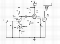
From present day posts/ web pages, the matter of picking a driver is boiled down to current through the driver matching the grid current of the driven tube with the grid bias voltage of both driver and driven tube being the same. For this it's easy enough to set with adjustable voltage source at the plate of the cathode follower. So with the DA41 that I have been playing around with, that part of it has been pretty easy to do. Roughly 8mA at 20V.

The thing is , you can get that with a pretty large number of tubes. With the above numbers in mind I first tried 6CK4, 6V6 (Triode), 6K6 (Triode), 6BX7 (the 'BX7 surprised me by sounding so bad). Having one from a dismantled project, I also tried the 10 as driver which will work because it can be set at 8mA/20V pretty easily . (Sounds nice but needs a DC supply and if the Dynamic Couple concept isn't inherently flawed then I think there must be a better driver)

. . . . . so then thinking a higher gm tube might be the ticket, I tried the 
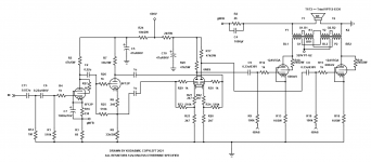
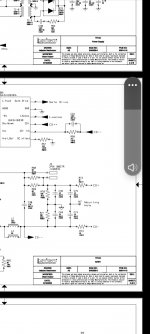
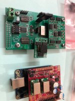
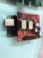
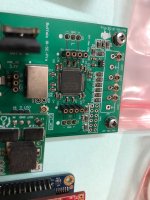
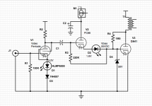
D3a (Trioded) and PC86 with bias resistance in series with the coupling and grid resistor to suit. (shown below) . The PC86 was for whatever reason the so far all round best sounding at low signal voltage but clips early - maybe because of it's low bias voltage of about 1.6V.

So , what's the question? With the results being so varied among the tried tubes - all but the D3a and PC86 able to meet the published requirements of Vbias @ Ig without special help - I think there must be some other parameter that determines what will match the driver to driven tube in a way that will work best. Intuitively - Intuition is all I've got here, certainly no engineering expertise - the problem of putting the two in series this way must mean that along that series driver cathode to output grid current path both tubes need to agree with each other or else one will tube get in the way of what the other tube is trying to do.

In an earlier article on his 2B6 (in attached "Radio Engineering", I think there's a clue where Stromeyer says " . . . . the characteristics of the input (ie. driver) section are arranged so that its internal impedance varies with the amplitude of the signal to maintain a constant ratio with its load. Hence the developed voltage is not influenced by changes in its load value. In other words, the voltage impressed across the input of the second section is not affected by variations in the grid impedance of this section." But I have no idea what to do with this.

I would like to find a more comprehensive way of matching the driver characteristics to the output tube without having to wire up everything under the sun. Any ideas?

Thanks for any suggestions.

Attachments

  • IRE-1936-07.pdf
    IRE-1936-07.pdf
    3.4 MB · Views: 138
  • Radio-Engineering-1933-08.pdf
    Radio-Engineering-1933-08.pdf
    1.8 MB · Views: 114
  • Dynamic Coupling Driver Bias Full 20V.png
    Dynamic Coupling Driver Bias Full 20V.png
    12.5 KB · Views: 260
  • Dynamic Coupling Driver Bias Added in Series.png
    Dynamic Coupling Driver Bias Added in Series.png
    14.1 KB · Views: 215
  • DA41 Curves.jpg
    DA41 Curves.jpg
    478.5 KB · Views: 188
  • DA41 10KΩ at 600Vp:60mA.jpg
    DA41 10KΩ at 600Vp:60mA.jpg
    206.7 KB · Views: 211

DIY line isolation transformer? (Luxman lt-1000 similar?)

-I am completely newbie what it comes to electronics, i have built a kit pre but thats it. Asking advice about choosing right transformer:

----------------------------------------------------------------------------------------------------------------------------------------------------

My friend has Luxman lt-1000 between his dac and preamplifier, and i like what it is doing.
Also it seemed to make something audible to the sound overall which i liked.
I haven't come across this kind of device before so read about it and understood that basic principle is to get rid of ground loops with line transformer.

https://www.jensen-transformers.com/what-is-a-ground-loop/

Anyway, in my summer house there is grounding problems with signal route, so i want to try any kind of solution to get rid of it.
(and also try it in my main system, littlebit of hum in there)

I have ordered cheap one from Audiophonics (Audio isolation transformer), but if it works out i would like to try to make a good sounding one myself.

----------------------------------------------------------------------------------------------------------------------------------------------------

-Maybe this is more than bit overkill, but does line magnetics have transformer in its line that could work here?
IT-01/25? IT-05?
https://www.monolithmagnetics.com/products

-Lundahl?
if you have experience with this, would you recommend some other manufacturer? vintage? open to try anything here..

Attachments

  • luxman_lt_1000-1.jpeg
    luxman_lt_1000-1.jpeg
    30 KB · Views: 168
  • luxman_lt_1000-3.jpeg
    luxman_lt_1000-3.jpeg
    34.8 KB · Views: 78
  • s-l400.jpeg
    s-l400.jpeg
    27 KB · Views: 74

Box Volume & Port Size Question.

Hey guys, hope you're well. I just have a couple of questions regarding box volume and speaker port size.

I'm attempting to build a 2 way bass reflex bookshelf monitor for a university project. I know there is a lot of software out their but i'm trying to manually do as much as poss so I can explain my workings out so there's more to write about. I know its pretty backwards to validate it with software I just want to learn as much as poss.

I'm going be using the Dayton Audio RS150-8 for the low/mid woofer
Dayton Audio - RS150-8 6" Reference Woofer 8 Ohm

For the tweeter i'm going to be using the Dayton audio DC28FT-8 1-1/8"
Dayton Audio - DC28FT-8 1-1/8" Silk Dome Truncated Tweeter 8 Ohm

I've chosen to go for the QB3 box alignment.

I was just wondering, is it ok to use the QTS provided by the manufacturer, when using the box alignment table, or do you have to include the 'series resistances' you expect in the Qts value, however you go about doing that?

In regards to box volume (ignoring series resistance thing) I. Here's I have managed to get a VB of = VAS 16.6 L / A 1.9699 = 8.426823696634347 Litres

One thing that confuses me is, do I need to include factors such as the damping, crossover etc in this final box volume before calculating the port length? Or can I do all the calculation and then just add on the volume to adjust the overall box size without it affecting FB, port size etc?

I managed to get a port length of 7.94194 inches, but this seems quite big?
Imgur: The magic of the Internet

This is with a diameter of 2inches too. How can I go about shortening the length? I understand that I may have to increase box volume but i'm unsure how this will affect other parameters such as FB, and if I change FB how it will affect the rest.

I hope this makes sense. I have been trying to figure it out before heading to the forums but my brain is in a pickle.

Thankyou in advance.

Possible DIY Voigt Speaker project question?

Hi All.

I came across a vlogger who described design aspects of his Voight Tube Speakers & demonstrated the science behind his final design.
I'm drawn to this design as it does away with the cost and complexity of crossovers, & the cabinets are straight forward to cut and build.

The design features 8" full range drivers, and combines transmission line design by using tall tapered cabinets and with porting with a horn shaped mouth for the horn effect.
Tuning is performed by packing long fibre material in the top section of the tapering cabinets.

One of the key parts of his design was the cabinet material choice and the way he dealt with dampening issues.
He chose 3/4" plywood, and dealt with stiffness & resonance by gluing sheets of MDF internally using a compound called Decicamp dc30.
The polyurethane damping paste resulted in acceptable levels of deadening the walls of the cabinets.
The paste is northward of USD$150.

Is there a better/less expensive way of dealing with resonance issues?

Login to view embedded media

Replace Jordan JX92s?

I know a guy who has a pair of Jordan Jx92s.
He has them in a 13 liter bass reflex. He complains that he lacks warmth in the midrange. He wonders if he can replace the driver with one from Alpair.
Unfortunately, I haven't heard the Jordan Jx92s, so I can't recommend any in particular. Maybe Maop can be in the right direction or not.
What do you think about this?
Anyone listened to the Jordan Jx92s?

WTB Shure SEK 2 stylus microscope..

I have been looking for some time now...no luck yet...Having built up a fair collection of vintage carts, I'd really like to give them a proper inspection when they arrive.
I have tried the USB microscope....eye loop....different magnification methods, nothing that I'd be happy to continue to use.
If you have something you think might work please don't hesitate to let me know.
I live in Canada...thanks for looking ....Marc
Projects by fanatics, for fanatics
Get answers and advice for everyone wanting to learn the art of audio.
Join the Community
507,556
Members
7,876,720
Messages

Filter

Forum Statistics

Threads
405,712
Messages
7,876,720
Members
507,556
Latest member
Syracusejim