First of all, Sorry for this long and probably difficult to follow post. I tried to make it simple but also provide as much info as I could so no-one has to go looking for it. - Netting a long and wordy post. Apologies.
So called "Dynamic Coupling" is often attributed to Japanese designers but as the Japanese sites all use the same term in Katakana - a script reserved for use with terms imported to Japan from other languages, I figured that it was probably to be found in an earlier Wireless World , likely first tried by a Brit. I was wrong . It comes from the USA's Charles F. Stromeyer who published his paper on it in Proceedings of the Institute of Radio Engineers in 1936. (Attached)
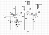
From present day posts/ web pages, the matter of picking a driver is boiled down to current through the driver matching the grid current of the driven tube with the grid bias voltage of both driver and driven tube being the same. For this it's easy enough to set with adjustable voltage source at the plate of the cathode follower. So with the DA41 that I have been playing around with, that part of it has been pretty easy to do. Roughly 8mA at 20V.
The thing is , you can get that with a pretty large number of tubes. With the above numbers in mind I first tried 6CK4, 6V6 (Triode), 6K6 (Triode), 6BX7 (the 'BX7 surprised me by sounding so bad). Having one from a dismantled project, I also tried the 10 as driver which will work because it can be set at 8mA/20V pretty easily . (Sounds nice but needs a DC supply and if the Dynamic Couple concept isn't inherently flawed then I think there must be a better driver)
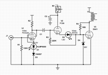
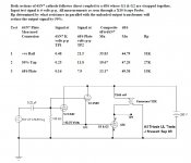
. . . . . so then thinking a higher gm tube might be the ticket, I tried the D3a (Trioded) and PC86 with bias resistance in series with the coupling and grid resistor to suit. (shown below) . The PC86 was for whatever reason the so far all round best sounding at low signal voltage but clips early - maybe because of it's low bias voltage of about 1.6V.
So , what's the question? With the results being so varied among the tried tubes - all but the D3a and PC86 able to meet the published requirements of Vbias @ Ig without special help - I think there must be some other parameter that determines what will match the driver to driven tube in a way that will work best. Intuitively - Intuition is all I've got here, certainly no engineering expertise - the problem of putting the two in series this way must mean that along that series driver cathode to output grid current path both tubes need to agree with each other or else one will tube get in the way of what the other tube is trying to do.
In an earlier article on his 2B6 (in attached "Radio Engineering", I think there's a clue where Stromeyer says " . . . . the characteristics of the input (ie. driver) section are arranged so that its internal impedance varies with the amplitude of the signal to maintain a constant ratio with its load. Hence the developed voltage is not influenced by changes in its load value. In other words, the voltage impressed across the input of the second section is not affected by variations in the grid impedance of this section." But I have no idea what to do with this.
I would like to find a more comprehensive way of matching the driver characteristics to the output tube without having to wire up everything under the sun. Any ideas?
Thanks for any suggestions.
So called "Dynamic Coupling" is often attributed to Japanese designers but as the Japanese sites all use the same term in Katakana - a script reserved for use with terms imported to Japan from other languages, I figured that it was probably to be found in an earlier Wireless World , likely first tried by a Brit. I was wrong . It comes from the USA's Charles F. Stromeyer who published his paper on it in Proceedings of the Institute of Radio Engineers in 1936. (Attached)
From present day posts/ web pages, the matter of picking a driver is boiled down to current through the driver matching the grid current of the driven tube with the grid bias voltage of both driver and driven tube being the same. For this it's easy enough to set with adjustable voltage source at the plate of the cathode follower. So with the DA41 that I have been playing around with, that part of it has been pretty easy to do. Roughly 8mA at 20V.
The thing is , you can get that with a pretty large number of tubes. With the above numbers in mind I first tried 6CK4, 6V6 (Triode), 6K6 (Triode), 6BX7 (the 'BX7 surprised me by sounding so bad). Having one from a dismantled project, I also tried the 10 as driver which will work because it can be set at 8mA/20V pretty easily . (Sounds nice but needs a DC supply and if the Dynamic Couple concept isn't inherently flawed then I think there must be a better driver)
. . . . . so then thinking a higher gm tube might be the ticket, I tried the D3a (Trioded) and PC86 with bias resistance in series with the coupling and grid resistor to suit. (shown below) . The PC86 was for whatever reason the so far all round best sounding at low signal voltage but clips early - maybe because of it's low bias voltage of about 1.6V.
So , what's the question? With the results being so varied among the tried tubes - all but the D3a and PC86 able to meet the published requirements of Vbias @ Ig without special help - I think there must be some other parameter that determines what will match the driver to driven tube in a way that will work best. Intuitively - Intuition is all I've got here, certainly no engineering expertise - the problem of putting the two in series this way must mean that along that series driver cathode to output grid current path both tubes need to agree with each other or else one will tube get in the way of what the other tube is trying to do.
In an earlier article on his 2B6 (in attached "Radio Engineering", I think there's a clue where Stromeyer says " . . . . the characteristics of the input (ie. driver) section are arranged so that its internal impedance varies with the amplitude of the signal to maintain a constant ratio with its load. Hence the developed voltage is not influenced by changes in its load value. In other words, the voltage impressed across the input of the second section is not affected by variations in the grid impedance of this section." But I have no idea what to do with this.
I would like to find a more comprehensive way of matching the driver characteristics to the output tube without having to wire up everything under the sun. Any ideas?
Thanks for any suggestions.
Attachments
-
IRE-1936-07.pdf3.4 MB · Views: 141
-
Radio-Engineering-1933-08.pdf1.8 MB · Views: 117
-
 Dynamic Coupling Driver Bias Full 20V.png12.5 KB · Views: 267
 -
 Dynamic Coupling Driver Bias Added in Series.png14.1 KB · Views: 221
 -
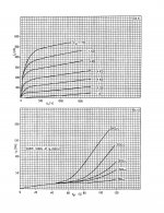 DA41 Curves.jpg478.5 KB · Views: 190
 -
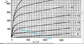 DA41 10KΩ at 600Vp:60mA.jpg206.7 KB · Views: 212
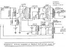
There was quite a bit of further information published on the data sheets covering the Triadyne products
of the company the 1935 paper was written. This design was offered in a few cases but never caught on.
I was curious regards the 6B5, 6N6G & so on about 20 yrs ago. But I didn't want to buy any of these tubes,
I formed something by using a 6SN7 driving a 6F6. It worked well. But Rockolab had already built a small
commercial PP amp with 6B5s so I let it go at that.
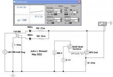
Much later I got going again on that & finally wrote a test report, copy here. The paper includes test data
running the composite tube in pentode, UL & triode mode. The paper also includes a test on reach thru of
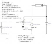
the driver plate. Last Spring I used Electronic Workbench to simulate triode & pentode connexions
to determine rp of the composite tube.
By your choice of power tube the proposed amp looks like something of much larger magnitude.
And a degree of danger. Would have trouble getting this one past the safety regulators! 😱
of the company the 1935 paper was written. This design was offered in a few cases but never caught on.
I was curious regards the 6B5, 6N6G & so on about 20 yrs ago. But I didn't want to buy any of these tubes,
I formed something by using a 6SN7 driving a 6F6. It worked well. But Rockolab had already built a small
commercial PP amp with 6B5s so I let it go at that.
Much later I got going again on that & finally wrote a test report, copy here. The paper includes test data
running the composite tube in pentode, UL & triode mode. The paper also includes a test on reach thru of
the driver plate. Last Spring I used Electronic Workbench to simulate triode & pentode connexions
to determine rp of the composite tube.
By your choice of power tube the proposed amp looks like something of much larger magnitude.
And a degree of danger. Would have trouble getting this one past the safety regulators! 😱
Attachments
-
 Rockolab PP 6B5 Amplifier 12W.jpg183.1 KB · Views: 118
 -
 6SN7 6F6 SE Direct Coupled Amplifier.jpg71 KB · Views: 131
 -
6B5 Triadyne.pdf554.3 KB · Views: 78
-
Inverted Triode B.pdf619.7 KB · Views: 88
-
 6SN7 6F6 Composite Tube as a Triode w Captions.jpg53.6 KB · Views: 117
 -
 6SN7 6F6 Composite Tube as a Pentode w Captions.jpg56.3 KB · Views: 124
 -
 Modulators 12AX7 807.jpg52.6 KB · Views: 121
 -
 6ac5_6p5 Amp G.jpg46.4 KB · Views: 125
Thanks !
I did look at the sheets you mentioned but didn't see anything that would help in picking drivers by data-sheet in a more than general way. My guess is that to do it right I'd have to match curves on the driver with grid curves on the output.
Truth is, I was attracted to the circuit schematic by the visual impression that it might be sort of like Tubelab's Power Drive . . . . or at least as close as one could get with a tube and without needing another voltage supply . . . . . maybe.
(DHT amps get cumbersome enough with the DC filament supplies.)
Probably the best next step is to look at a conventional cathode follower before bowing to the inevitable and making a -V supply and putting in the Mosfet. . . . . . . . but not quite yet.
I've found a few posts recommending use of a choke load for cathode follower so will give that a try as well.