For Sale JC2 Clone Preamp Board with Transformer

For sale: JC-2 Preamp clone board with transformer...works great.

I remember years ago reading a thread where Mr. Curl advised the ideal voltage settings for the JC2 for both channels...they are all set as advised...just don't use it anymore as the chassis was repurposed to a Korg B1...

How's $50 + ship (should be cheap - small flat rate box - conus)

Attachments

  • PXL_20230130_183744251.jpg
    PXL_20230130_183744251.jpg
    495.2 KB · Views: 188

For Sale 4U 500mm Dissipante chassis (Pico's Toxic Masculinity Class A Amp Chassis)

For sale is a 500mm deep 4u Dissipante chassis. I bought it as part of the group buy ran by 2 picoDumbs, but didn't end up using it.

It comes with the inner steel mounting plate and the handles at the back. It also has a square hole machined in the front panel which I was going to use to mount a power switch.

For more information on the chassis please see the following threads:
https://www.diyaudio.com/community/threads/picos-toxic-masculinity-class-a-amp-chassis.362494/

https://www.diyaudio.com/community/threads/ultimate-4u-500mm-chassis-who-is-interested.360807/

Price: 200 AUD

Attachments

  • PXL_20230126_081004846.jpg
    PXL_20230126_081004846.jpg
    608.8 KB · Views: 161
  • PXL_20230126_081014210.jpg
    PXL_20230126_081014210.jpg
    419 KB · Views: 171
  • PXL_20230126_081049079.jpg
    PXL_20230126_081049079.jpg
    376.9 KB · Views: 160
  • PXL_20230126_081223348.jpg
    PXL_20230126_081223348.jpg
    789.9 KB · Views: 172
  • PXL_20230126_081244299.jpg
    PXL_20230126_081244299.jpg
    492.1 KB · Views: 176
  • Like
Reactions: ronex

C++ Easy and Scalable Software for BIII38Pro

Hi guys,

I have been looking for good, easy and scalable software for BIIIDAC, but couldn't find anything useful. I know, there are some guys writing the software, but it is mostly C or Microcontroller based and very difficult to follow or change.

I decided to write easy to follow software, based on C++ classes, which is as close to TPA Firmware as possible.
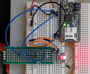
I use Atom + PlatformIO and Arduino DUE for this.
For remote control i use Apple Remote and the Display is 4,3" 480x272 TFT LCD mit Touchscreen SSD1963.

The software is based on TPA firmware, it behaves the same way: power up, reset, communication, configurateion, etc... is all based on TPA firmware.
The software gives you at this stage basic interaction, like volume change and input change, the rest of the configuration is read from the switches on the BIII board.
This software is easily scalable, you can replace any of the classes with your own or modify existing.
I have added some "interfaces" for editing, like eeprom or touch (didnt test the touch, but its easy to figure out how it works and correct it).
I also prepared the settings page for the tft screen so one can add it later on.


Main function is literaly 20 lines of code, it just takes the action from interface and apply to the DAC class.


As I said, the heart of the DAC Class is TPA Software.
The configuration file is the copy of TPA, ES9028_38.h file.
DAC class constructor is build of TPA functions, slightly modified for Arduino needs ( i use Wire.h for I2C communication ), but the funtions:
powerDACup();
initializeDAC();
configureDAC();
are practically the same you get with TPA firmware, those work the same way and are called the way TPA is doing it.


Simplified soft looks like this:
//--------------------------------------
setup:

dac = new DAC();
remoteInterface = new RemoteInterface();
touchInterface = new TouchInterface();
tftGraphics = new TFTGraphics();

//---------------------
loop:

action = remoteInterface->getAction();
if( action == NONE )
action = touchInterface->getAction( MAIN_MENU );


if( action == NONE ){
dac->readSwitchStates();
}


switch ( action ){
case NONE:
break;
case CHANNEL_LEFT:
tftGraphics->printChannel( dac->decreaseInput() );
break;
case CHANNEL_RIGHT:
tftGraphics->printChannel( dac->increaseInput() );
break;
case VOLUME_UP:
tftGraphics->printVolume( dac->increaseVolume() );
break;
case VOLUME_DOWN:
tftGraphics->printVolume( dac->decreaseVolume() );
break;
case ENTER:
tftGraphics->printVolume( dac->muteVolume() );
break;
default:
break;
}
action = NONE;

//-------------------------


All you need is Atom + Platform IO + ( Arduino Due, remote, TFT) and the repository:

GitHub - poninskit/TPA_Buffalo_IIIsePro38_Software: c++ Microcontroller Software for Buffalo III 9038 Pro DAC

happy coding.

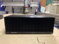
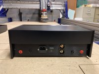
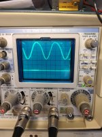
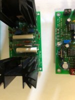
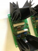
here is how it looks like:

yqQ9CrrVu7Xb7bB5EOSaX3syui8JQDgekV3C0vzfhpB50Ts14nL_5qqSfa-5uBWXlxchDBVvNY-aBYIbZ6O6lKmd6GLhyO1bUiFTyI-CyNzCQqWMccbE78AaMSAHlFCVcXOZAhWz75iA8g5X4Tl9LAtLf9jCmD6hPGd-98JHRdehFDZ5FyZh9K2jfPah9j6rrLExJRpOeDui1UMz3TY0I8bA0g59LuWsxXn7q7cAlYgWq_DIGzMCyv-Tqk4flPTaKnZ7s3RJqr1pCxML1qLrwyUZytKhPQ1rLyCAvFdCTZbNycD5YGwoCdmdYC2bF6H5PR77D_VUYl7jPc6jSZi0ttjQw0R-uAya5-b4iVKukzJKcWtG1Ly-9ngr_ZgmWWIrJ5PP2Gkw3jmedrOMgNwKqv6Zlq2W0UYHB-l1f4zJxKuDkK-tbKI1LgIyzXgSz7rkJcU8yem0Ec71n-JgOiZqQlBXTUEu2D7_FNt2laGy7HwkhlcbpVbKEWgJAGNqMuYJj3rVx7z-XxdhN7SBMLYtai6PGzJuGrkBntoAK1fJ_QQUazjbF2Wa7BIDOuuB8MOBzTiJ-9Vpe5y6lpMZL6wHQ_4oYjdJ947LiGNV0ldSkKygpIn0qbqEqH8fi2DF_328lwrtgcogi0T42Y5MLhH_qCyEZfeUpB8=w629-h472-no


KxyP3k0N8YXF9lDxv3I8Y8xbGcpE-hKz_hzo5Fuop9frTlU8HqZufYSJRjNKnJ_NVJOTWDRR2Ud0grGy-eBTYfE6GvskEuF1P1rYPcF9Y_oOpVI0iFFgKwU9_kYLGFAGb3moU6uzfHhZyUJ0sskghIQE0Vsyt7ne0BBfPdMJRmGhjTZRbuknWelInA6cveBholIb4g-oS6bQEeNqNZLTmZiSbqrVHnPLz0NFq_SgEqqmu-BdKPUYsbdVC_aA0ar75EmqzIJHWZuH3iMbCvavcHHir4TY3hc4MEy1U-4RAtl6_7EZ6a4LmeQujjDBKWYPBisAcLC27RbanLlIzlm6MznOPlLpPqLTiGWQJGQcu_EBAa0M4PcUuzaRFR8btEbRGBGggmm2wqWqCkPUmq9dMn0F65r4OdPvuAugCqA5Uo7elQszUTmA3IoCCCN_amrB3UqbTR0J81R_-EHnJjBboMEudz_VXUJSrCpPfAbquzwSjUJz-N96ILliHtP7UIWrX2gfSMAma-YnFJu4QWY3znuDit8rX-fY2E0bH_-yYfgP7vOLJBZFiANAKZEIjGrhJXvlbf5nSdrgIKh1ATj0RpeeGYHTUGyrHGBbhNMhDOwTQLYItyu_R8V6fVrsjT29dAwPAAWlrabRqjpWJQc267pSz2RRQqM=w768-h291-no


zkRqDPEuRi6vSUFmGQ9mrf87AA4T5VbU8Cb9EACm9nOUybnZXs1Re1Izrj9AbYUArMhCHroG-LFfvDBh6mulLn1PlGjPxeMP5GuyHyDI7EAnqnuUlGMTet6GmbK4ptn7QKWT-xVbcnLstCNOC2dYd8ouSijqmZOH1XOF0IVoZqdbsU3niNNCudEN-SLmm58JGlF8tpCGLJpkLAgSBM3GHUvT4JFicfwjm06v_FZ-pIthaZKG_rMpVnJN1VDMdWTYLUS1P2Lhndt3NtlXp2zJEJqS8G4AwZE-yqRWQJCmNeQ8MA2glMnG8oxqGCn3zIiGMhCxbFEcakv4HFRJVAVw6asx__9zJd0VoDb6v4KEnyzNyZGvg1tWau4yjpzAWQWer63mkIzwQ9xOUH7yaCoAfg1jGh9-q9KPTFgHpm0lFhlUREZ1lOrhYkXBo9URFt_iMHNm_opKwlZU9CgbAuyso6VOqJXSqAIgT4F3CfBEFSxYspUgVtbiUeD8_liipG6oTqEEvQ72NkL-AHhjQu4NEyQ1VxzThtQ7XctJpkrnfTLWQC9XB3ptU9g0BmN8KW-KK8b-Sf8Rk2UEguhy3r7Kni3tBfcTkU5OcpoEnaXHNlJUNBqLxosO7k9Rk0h1dF9g8u3rM_PgY6DRlnK7WQ-xS5GBCXZVcNo=w707-h472-no


Mw6W0y_rPa2mg_m24aCDC9DSnqNeL5vcxooC5GJB87a0pS_lg7j2r7SFaywXjTHNqvj2t3zNMyUaj1IJLLp8YpdzHwAgI9D0sfbK3FcTKTf1CD55Hx6Q-44J9ACUwgMSNU3Yxml-iGZ6lhWiDPui2BXpDrkTydcB4lIyyuTjRq3OEGY7TV7d45tGCJDf8FOhYUAnHxfwUjjmIIRBonTiRBegGxjINz3DkmFFC-mbaeqtn4E1fAQjA0dHlIXQzQlucX0c1g0Zmp6ksbrDi7EQCDjPHdgu9P77j22hrDM7CH6c4OBnP3sofzmTegn8GODdxKqkcyIZQBn6TaFk8nEzQjHxbpDO-QUzEvBVxnBZWwMJoif2tJ2S1honc9rGMnOWP9bUV91l_yMYc9DTc_M4Fr5tmnTIY7GjILbBR5BUQGNIHew7HFNyyMNtcWfTQi9ShyrgW1LuAUpHg5KO3filFg3QemZHs4eODkl53l7OMQYqiAkEsjoYlvODz5nOOhWo9p_gQCj1hRvqAkbiQjqDdPlbYtYquBkUpuoYbosfvanQG_dwOv71rrL1sKowmY7dyKCkdFA2JpyuLO4JI7tpmB4XGpUV3NLv9HXg6PMl-AiYMzXV1OdV4d5KVF8Ho-NRIrbFu1OTNtYVAsbSG2HPmKtrA-Z7u4I=w708-h943-no


Optional DAC settings page could be written like this:

3VV3ScWokz9P-rWTDtX6Il9m_i-qgAycaq2Wv4CugTL94bN_KFR89jJ3V3DgusqjRMNNy7tUkGygcbna4ERSwbhnwU7PCOzGwcD1EYfNeRIyWEht_WI3bEEHhASw5xXXo6Djl6JlBCV2dMLS5k9bEaSYQOH4TyqPkNjTEFkA7ioWdTX4DsyQGzoiWeXGFt0RiLMBZEUqvMdNdhp1QHrZyIA5gktWkIrx2eyS4_67cuKAsNLM2heh5xMegR4wE1wk_Xa7O2I0z7sMkQdl9Mt5Y2EMDwyLuITmQNQjdwnsm7HOuWItTOVh-rX_jH2iWQGCc_p0lkncbYBuezyjjnX0jaiIKFg8efULXlfNeLQe_DSq-lFBeuszi0-u7naRyvKzF4Nk0UwvCbYXN0gcKvKlYsn6IfVGN_GUeR2BFnTIpb1ClbsiasApL7veCMTPTTJc2kbxnYKca6DAJzYVgudCZm6sy-M0wtLzxH570LYGKWFNMZM-J9HisNJDPyiBdyP2V5JnWR7mNDOY6NEI1uGSgKvVEZTW6xXZc_U8kORNu8rMysxa1murM3uHzDY2rWTZH_RwXs4VG_y46EEzCOrnetNqLdm1xEkaZx-OeATPh2dFCU6JTCspw0KKsxiiiq1Q6OPM00QGryoLQVjwuo3-MqmGFY27pyk=w405-h276-no


and this is how it works:

VID_20190507_095456.mp4 - Google Drive

Internal balance adjustment?

I have an old Pioneer KE-2323 cassette stereo in my car and the left is louder than the right. balance adjust helps, but it's definitely something with the radio itself. Is there a 'master' balance control or something somewhere, maybe inside I can adjust? I'm handy with soldering etc, so if anyone can point me in the right direction, I'd appreciate it!! It's an old Jeep CJ-7 and I want to keep the original shaft-mount setup.

T+A A1530 power amp needs repair AS-IS

SOLD

I am posting this here because this unit needs a repair but will post to other sites later if I don't get hits here.

When powered on, the left and right speakers pop and there is no sound coming from the speakers. That's all it does.

Again, the amp powers up. I talked to T+A Germany and this is what they said and I quote.

"The pop noise that is being complained about indicates an offset in the audio signal. There must be DC voltage in the audio signal. It is somewhat unusual that this is audible on both channels. In this case, there must either be something wrong with the unit's power supply or the offset control of the power amplifier circuits is not in order".

The unit has some scratches here and there, it is door/lid does not close all the way but this is only related to the small plastic mechanism not holding the door/lid. The bottom metal feet have thin plastic stickers that are missing, easiest fix. If you must need more photos, I will take them for you.

Again, the unit has few scratches but no busted corner or huge dings or similar.

Please make an offer as I have no way of knowing what is worth the way it is. I know that the MSRP was $7500 like 12 years ago and they go for $1500 on used market.

Will ship anywhere but it is pretty heavy so shipping won't be cheap. My zip is 33326.

Attachments

  • F1DD5EC2-B2FE-4465-AC5D-98D86285A11C.jpeg
    F1DD5EC2-B2FE-4465-AC5D-98D86285A11C.jpeg
    162.3 KB · Views: 192
  • 81DF77F1-9B5E-4CAA-ACE4-B6E32E60F615.jpeg
    81DF77F1-9B5E-4CAA-ACE4-B6E32E60F615.jpeg
    377.7 KB · Views: 139
  • CA5C5467-0C4A-470D-BC09-59AB8A1FF8AC.jpeg
    CA5C5467-0C4A-470D-BC09-59AB8A1FF8AC.jpeg
    156.7 KB · Views: 140
  • 2AEF86D0-3C35-4006-934B-754106EA71B1.jpeg
    2AEF86D0-3C35-4006-934B-754106EA71B1.jpeg
    310.1 KB · Views: 136

10-25 Hz, is it necessary for HT or Music?

Ok, I have this friend... let's call him Joel Ahrens.

Now Joel has 2 subwoofers stacked on top of each other. Both are 10-12" subs. One of them is a MK brand sub. He uses the system for both home theater and music. As far as I can tell both subs are fed the same under 80hz signa from his Rotel multi-channel preamp/processor.

Now I keep telling him of the joy of DIY speaker building. And he scoffs at the concept.

He says he'd consider a DIY sub if it was 18" and could hit 10hz. He says he'd use it in ADDITION to his current 2 subs.

Ok, so how silly is Joel being? He says if I build him an 18" sub that can hit 15hz he'd be all over it.

So is there an 18" driver that can comfortably hit 10hz and costs less than $1000. Also, is there ANY real movie or music content down that low?

Victoria Regal 2 SE parallel tube swap amp

I'm in the process of building a little parallel SE guitar amp and came across the Victoria Regal 2 amp (SE parallel cathode bias) , which says it uses an "adaptive transformer" to allow the user to use any of the octal output tubes . 6V6 up to EL34 in any combination without switching or re-biasing. It says it uses a Bi-filar transformer , which means each output tube has it's own winding , and I understand that bit , but how do they manage with the different impedances required by different tubes and the different cathode bias resistors? By all accounts the amp has a very good reputation sonically , but I can't find a schematic or any description of the circuitry involved , or the transformer.

The pilgramage of the humble disciple doth he bringeth unto the realm of the True Believers. Profound truths shall be his everlasting reward.

Hi.
Right, so, I dig big rigs. That's my thing. I'm fascinated by anything audio, but my passion is desiging and building big ol' PA systems. I did that for like, 15 years or so, and I've built around a hundred speakers, mostly for PA use. BUT, being taught by engineers from the HiFi world, sound quality is of paramount importance to me. Most rig builders aim for maximum volume levels, at the expense of a good response, but if you know the tricks, then (as you guys will already know) there are ways to make your rig louder AND sound better. There is no way to describe the feeling when you set up your system at a big party, right next to a wall of super-expensive professional kit, and everyone dances in front of yours, because it sounds so much better and louder. Every party is like when you bring your friends around to listen to your new HiFi set up, except there are hundreds of them, they don't leave when the snacks run out, and none of them will help you clean up afterwards. Admittedly, professional systems have improved massively in the 12 years since I last built one, but when big companies design systems, they are always hindered by factors that an individual can overlook, like portability, appearance, keeping up with expectations (competing with what the other companies are producing), cost-effetivity, etc. We can be more cavalier in our approach. I don't care if my speakers look odd, or are really heavy (they will be both). Just so long as it's really loud and sounds amazing.
My last rig vanished unto the ether years ago, but the obsession has returned, and I'm designing a new one.
I never finished school, never mind study engineering or physics, I have an ASD, and I'm pretty sure I have discalculia, because maths is really hard for me, but I know enough about sound systems to talk ad infinitum. The problem is that with these new designs, I'll be going deep into the technicals, and there will be things that I will struggle with, and I hope that this communty of fellow obsessives will guide me through the headaches and losses of reason, and deliver me unto the dazzling glow of audio understanding. Years from now, many party-goers will be subconsciously, yet eternally grateful that you helped me build a thing that kept them dancing all night long, because it sounded so good (and if they don't dance, we''l just blame the band/DJ).
Thank you all in advance for your help (or should you be thanking me for the chance to show off how good you are at this stuff? 😛).

REW Java drivers

Greetings

Messing around with different devices for output and capture in REW I found something I don't understand. When using multichannel devices for output on HDMI, I have to choose Java drivers. The manual says Java drivers only work with 16bits, but there is an alternative called EXCL witch changes the output to 32bit. I have tried searching but cant find any related information. Does anybody know anything regarding this?

REW java.PNG
REW java output input.PNG


REW java EXCL.PNG
REW java EXCL output input.PNG

For Sale Neurochrome Modulus 86 in QUAD 405 Chassis and Replica QUAD 34 Preamp

New build using Neurochrome Modulus 86 v3.0 in new replica Quad 405 chassis.

The Quad 405 chassis provides a handsome enclosure for a Modulus 86 amp build. The clarity of this amp is impressive. For more info:
https://neurochrome.com/products/modulus-86

This is the first solid state build I have done in decades, as I have done mainly tube amps. This amp is very accurate and very quiet. The amp as shown is for unbalanced inputs. I include balanced inputs that will fit where the RCA jacks are with no chassis modifications required.

$500 shipped USA

Paypal "fee free" or money order or personal check accepted. Located Asheville, NC.

Attachments

  • quad 405 (2).JPG
    quad 405 (2).JPG
    670.2 KB · Views: 445
  • quad 405 (3).JPG
    quad 405 (3).JPG
    619.2 KB · Views: 451
  • quad 405 (5).JPG
    quad 405 (5).JPG
    435.4 KB · Views: 374
  • quad 405 (6).JPG
    quad 405 (6).JPG
    435.2 KB · Views: 403

Measuring inductance (of an autotransformer) using tank circuit

1B9D0F7B-8E22-481D-AABD-FDBA8AC368D5.jpeg


Tonight I unsuccessfully played around with this tank circuit to see if I could see oscillations between the C2 and L1, with the goal of measuring the inductance of L1.

I’ve picked up various tips from YouTube videos. C1 is a blocking capacitor I believe this is to hide the DC 50 Ohm resistance of the signal generator from the circuit.

I’ve added the diode because I want an edge rather than a square wave (input voltage). The square wave hits the diode which then cuts off for the lower half of the cycle, this makes observing any oscillations easier.

I probe the circuit at the top side of the inductor with probes set on 10x.

Well, I could see no oscillations at all!

It’s bedtime, but my next step will be to mock this up in LTSpice and see where I’m going wrong.

C1 = 220pF
C2 = 10uf
L1 = 100mH (guess)

I expect oscillations around 150Hz with these values.

I configured my square wave frequency low enough and duty cycle so I have multiple 1/150Hz seconds gaps between pulses. If there were oscillations I should be able to see them.

Anyone see what I’m doing wrong or could clear up my understanding a bit?

The inductor is actually the primary tap of an Autotransformer. But don’t think it makes a difference?

For Sale PeeCeeBee V4H Rev 1 assembled amplifier PCB (set)

I have for sale a set (2x) of PeeCeeBee V4H amplifer (Rev. 1 PCB boards). As proven with many group buys so far, this amplifier is very popular, due clever design and great high end sound. Amplifier consist of high quality parts (mica, Nichicon FG capacitors, MPC resistors).

NOTICE: One amplifier channel works fine, other has blown output pair (2SJ162/2SK1058), due broken mica insulator. I suggest buyer, to carefully check both boards (after replacing broken mosfet pair ofc), before applying full power supply voltage.

Specifications:
Power - 150W/250W into 8R/4R load with +/-56V PSU (0.1% THD)
Frequency response(simulated) - ~2Hz to ~800KHz (-3dB)
Slew Rate - 100V/uS
Offset variation - +/-10mV
SNR - >110dB
AC gain - 24.5 (28dB)
DC gain - Unity
Input level for 250W into 4R - 1.5VRMS (~4V P-P)
THD:
100Hz 10W - 0.0005%, 100Hz 100W - 0.001%
1KHz 10W - 0.002%, 1KHz 100W - 0.003%
10KHz 10W - 0.002%, 10KHz 100W - 0.005%

You can read a lot more information about this nice amplifier here, together with all measurements:
PeeCeeBee V4H GB

Price for set is: SOLD

Attachments

  • v4.JPG
    v4.JPG
    322.8 KB · Views: 125
  • v2.JPG
    v2.JPG
    294.1 KB · Views: 118

Help needed - AD1865 + DF1704 + SRC4392

Hello friends,
I have acquired two AD1865K, and I'm researching my options on how to use them. My plan is to get the digital side done,m and then play with analog options. So the idea looks like this:
  1. USB to I2S interface
  2. SRC4392 as a DIR, selector, and ASRC
  3. DF1704 as a digital filter and I2S to AD1865 compatible signal converter
Sadly, I'm not really proficient with digital. This is why I'm asking for help:
  • I think that DF1704 with output format set to 18 bits will drive the AD1865 inputs correctly, is that right?
  • I need to set the SRC4392 output sampling rate to 96kHz (or 88,2kHz), to maintain compatibility with DF1704
  • Can someone point me to a source about aliasing and how it is filtered in the digital and analog domains? I understand that it is very important, but not much more.
  • Are those chips going to work in a configuration like this?

    Thanks a lot folks.

Preamplifier from Lineup & Fotios for fun

Lineup and me we have designed a line level preamplifier, just for fun 😀. It is based on our discrete module (upgrade of D. Jensen 918) that is also used in our phono preamplifier. There is a module called "JISBOS" and because we use exclusively BJTs from input to output we gave the name "BISBOS" 😀 to our discrete OpA. Benefits of BISBOS: 1) No expensive and hard to find jfets for input stage, just ordinary BC550C-560C 2) No need for excess class A idle current 3) No need for matching input transistors, output DC offset can be precisely adjusted from the trim-pot of LTP. 4) Same performance with JISBOS in unity gain (voltage follower) connection. 5) No need for complex power supply / stabilizer circuit, ordinary LM317-337 can do the work, just fine.
Here the schematic of... BISBOS:

Attachments

  • EAL discrete web.jpg
    EAL discrete web.jpg
    175.9 KB · Views: 3,482

NASA Validates 3D Printed RDRE Aerospike Engine

https://3dprinting.com/news/nasa-validates-3d-printed-rdre-aerospike-engine/

1675065833979.png


Copied from the article, did not use the quote function because of the "click to expand" thing was a bit too limiting on the text you can see:

RDRE​

Normal rockets use a single continuous burn to generate thrust, much like a huge firework.

A RDRE differs because it uses a series of small controlled explosions, or detonations, to generate thrust. Fuel and an oxidizer are injected into the combustion chamber, where they ignite and create a wave-like pattern of detonations that travel around the circumference of the chamber. This creates a continuous thrust, propelling the rocket forward.

The detonation process converts more of the fuel’s energy into thrust, and it can operate with a wider range of fuels and oxidizers. Plus, it can handle higher combustion pressures and temperatures than traditional rocket engines.

They not only use their fuels more efficiently, but they also have a higher thrust-to-weight ratio, and so they are of great interest to space engineers.

“Additive manufacturing certainly allows for very complex designs, but this novelty propagates and enables other new technologies such as advanced propulsion,” said Paul Gradl, Principal Engineer at NASA.

“Our NASA team completed hot-fire testing of an aerospike rotating detonation rocket engine (RDRE) enabled by Laser Powder Bed Fusion GRCop-42. The longest continuous duration operated with this hardware was greater than 130 seconds at 622 psi and accumulated over 10 minutes of total time. This is a huge step forward for RDRE.”

The RDRE tests were successful in proving their ability to operate for long durations while withstanding the extreme heat and pressure environments generated by detonations. The tests also demonstrated deep throttling and internal ignition bringing the technology closer to being used with future flight vehicles.

As a result of the test validations, a 10,000-pound class RDRE will be developed to compare the benefits against traditional liquid-fuelled rockets.

Switching crossfeed settings with relays

Hi,

I made a veeery long time ago an AMB M3 headphones amp, and incorporated inside the modified linkwitz crossfeed board offered at that time by TangentSoft.

I opted at that time to switch the crossfeed on/off and mid/high settings with a rotary switch three positions.

Time passed, and it seems this switch has become a tad rusty, introducing some distortion (audio signal had to come and go between the crossfeed board and the rotary switch).

A better solution would be to have the rotary switch pilot good quality relays close to the crossfeed board.

Now I never did this... The M3 has a 24VDC power, that will be used to actuate the relays. My Idea is to have one relay for ON/OFF crossfeed, being NC to ON and NO to OFF, and a second relay for mid/high crossfeed settings, being NC to mid and NO to High, so my usual listening position will be the no electricity required one 🙂.

But I have no clue which DPDT relay (OMRON or else) to use, nor the kind of active/passive components I need around the relays to have them working with the 24VDC power present inside the amp.

Thanks already for all your help 🙂.

Greg

Open primary on one side Push-Pull output transformer use as SE experiment

I repair a Heathkit W-5M amp, the output transformer with a B+ tapped primary was open on one side, but the ultra linear tap to plate tap was good.
I un-pot the transformer and hope the open wire was on the connection joint, but no luck.
The customer give me the bad transformer for experiment. I had a little Magnavox 8301 tube amp which the bass was weak.
I switch the Peerless 16458 in one of the channel for the Magnavox 8301 and the bass was improved a lot.

Attachments

  • 20230127_165202.jpg
    20230127_165202.jpg
    315.5 KB · Views: 170
  • 20230127_135135.jpg
    20230127_135135.jpg
    559.4 KB · Views: 143
  • 20230127_112502.jpg
    20230127_112502.jpg
    566.9 KB · Views: 118
  • Original tranformer 1Watt 50Hz.jpg
    Original tranformer 1Watt 50Hz.jpg
    446.2 KB · Views: 110
  • Peerless 16458 1 Watt 50Hz.jpg
    Peerless 16458 1 Watt 50Hz.jpg
    430.1 KB · Views: 115
  • 20230127_084840.jpg
    20230127_084840.jpg
    480.1 KB · Views: 139

LM3886 - TDA7293 - TPA3255 ... CHOICES

Tons of threads , hundreds of arguments and thousands of opinions................!
But nothing objective for those not in the know. Since all this is very individual and personal newcomers get lost in the mountain of info available here , and not only newcomers at times . So how to judge and choose the personal needle in this haystack ? Impossible ? I think not .

I think there might be a way to help a little . We all could establish a VOTING SYSTEM where to express ones personal choice , say like A is best , F is worst , and some way to accumulate results . on one side each voter could post the reasons for his/her choice and on the other the scores could be accumulated in a counter . AND : it would be a very democratic clear indication and summing up instead of thousands of opposing opinions.

At the very least it would show the popularity of each device at first glance then allow to investigate further if so desired , and act as a guide for those who happen not to be engineers .

Please let me know what you think . Thanks

Convert CT full wave bias supply to bridge recto supply (and drop voltage)

I am building Pete Millet's DCPP "Engineer's Amp". I am not using the stock PT specified in the schematic.

Rather than a PT with a 50V winding with a center tap (50-0-5), I have a transformer with a 130V winding (no center tap) (130-0).

I want to convert the stock bias supply (see attached) to be used with my 130V (no center tap) transformer.

I was thinking since no CT on my transformer I would just use a bridge recto. Then a 100V zener diode to bring the voltage down.

Stock bias supply puts out (1.414 x 50V ~= 70V) where the new winding would put out (1.414 x 130V ~= 180V). So I figure I have to drop at least 100V and the easiest way to do with would be with a zener. Thoughts?

Side note: what current does the bias supply itself actually use?

Attachments

  • Capture.PNG
    Capture.PNG
    53.8 KB · Views: 99

Audio Vactrol Assembly NSL-5162 & Test

Evaluated the Advanced Photonix Ceramic Photocell NSL-5162 as the LDR part of a Vactrol audio attenuator. It works well with an ordinary low-intensity red LED and is not too sensitive to ambient because my gadget has the LED bent over and atop the LDR. Another PCB has the test circuit with a driver transistor.

I drove the test procedure from the analogue pin of an Adafruit M0 dataLogger which has a true ADC. Most MCUs have fake ADC from PWM. Not good enough. Pin A1 provided analogueRead so that results could be recorded and graphed.

So the input to the test jig is linear but the LDR voltage on A1 is a curve. This does not matter for on-off operation such as muting. Otherwise, the control voltage needs to be corrected so that the LDR behaves like an audio pot.

Attachments

  • VAC3.png
    VAC3.png
    19.9 KB · Views: 80
  • Vac-jig.png
    Vac-jig.png
    77 KB · Views: 84
  • NSL5162-sch.png
    NSL5162-sch.png
    6.2 KB · Views: 91
  • Vactrol-graph.png
    Vactrol-graph.png
    16 KB · Views: 91

Active XO and Tuning; Sweeps vs White Noise

New to my system this year was a DSP and building a set of speakers that would be active XO'd. I do not have a space to tune in free space/anechoic so room effects are very real when running sweeps. The LF can be measured relatively decently near field, but the HF measurements dont seem to paint a clear picture of what's going on.

After many hours of both learning curve with tuning coaxial drivers with CDs I have gone between doing sweeps in the LP as well as tuning based on rta and white noise. It seems that tuning by sweeps in the LP and even when doing a couple positions near the LP room effects start throwing you down the rabbit hole.

In more recent tuning/refinement I have found that running RTA with white noise is quite effective as you can "wave" the mic around the seating position and fill in nulls or squash peaks that would have been very present in the static sweep measurement. This seems very hackish and non scientific but seems quite effective in getting good sound and not taking a long time measuring in many locations for each adjustment. Previous to this I had some shrill highs which was caused by eq overcompensation from 3 position sweeps. Another area I found great value in this method is fixing time alignments. Initially time aligning with fixed frequencies only aligns that frequency, watching the spectrum change around the x-over freq gets an overall better match across the overlaps.

Does anyone else use this as one of their tools/methods (not saying this replaces sweeps) for fine tuning in their XO and EQ?

Phono stage build with SUT (need some help)

Greetings!

I am about to build an EAR834p MM phonostage clone (with upgraded components) and also building a MC SUT made of two Lundahl LL1931 step up transformers. The idea is to put all of this into one enclosure. In the future I might expand this with a tube preamp part as well for DAC, CD etc but for now I will use my Vincent SA-T8 preamp and hook up my phonostage to it.

I have a lot of DIY inspiration and energy, but less actual knowledge. I have done a lot of DIY in other areas (speakers, boats, etc) but my knowledge in electronics is basic at best so be kind and gentle. 🙂

I understand the schematics on how to wire the SUT and connect it to the EAR834p but I would like to have two modifications that I would like some pros (you guys) to look at and guide me so I do not mess things up. I recently bought a used Rega P6 turntable with a Clearaudio Essence MC, hence the need of a SUT and a phonostage.

The two modifications I would like to implement are:

1. A switch for switching between the LL1931 two step up options 1:8 and 1:16. I made a schematic with a 4PDT switch that I think would work but perhaps I made a mistake. Please double check for me. 🙂 Pictures below.

2. I would also like to have a switch that can easily bypass the SUT in case I would like to use a MM pickup. I have made a schematic using another 4PDT switch that might work. However, during bypass mode, the circuit is still connected to the SUTs secondary coil. Don't know if this might be a problem (extra resistance perhaps?)? Please look at it and comment and give advice if needed. 🙂

Pic1: Schematics from Lundahl

ll1931.png


Pic 2: My 1:8/1:16 switch (this only shows schematics for the switch). The numbers in the switch are showing the corresponding pin on the transformer that it is wired to and not the pin number on the switch itself.

switch1.jpg


Pic 3: SUT bypass schematics. "In" on SUT is pimary coils and "Out" is secondary coils. Secondary coil is within the active circuit in bypass mode. Bad idea?

switch2.jpg

Can we have a sticky on how, when and where to use audio signals for testing.

Looking for info on how and when the following should be used. Sorry if this question has been asked but after days of searching and reading I feel I'm still missing something.
1. White Noise.
2. Pink Noise
3. Sine wave
4. Square wave
5. Saw wave
6. Frequency sweep.
The basic question is how would a person who is deaf. Test his audio gear, From Power supply to pre amp to tone control to amp to speaker. Using nothing more than a scope and a function generator. (China based or Phone / PC based.).
  • Like
Reactions: yoaudio

Help understanding Ian Canada configuration

I am struggling to understand all of the various parts associated with an Ian Canada DAC. I have printed out almost all of the manuals for each device and intend to pour through then to understand how they all connect together. I was wondering if someone has a sort of a diagram that indicates how the various parts connect together and which ones are required or optional. I am particularly looking to understand a core system that would be based on a raspberry pi. I would like to get something working with the bare minimum and then expand things over time. I would appreciate any help possible.

QUAD FM4 Frequency drift up at switch on

Hi,
My son purchased a known faulty Quad FM4.
The battery had leaked over a wide area of the LH side.
Initially after a clean up and replacement battery the memory and tuning worked well. the problem now, is that when switched on, the RH display digits flicker until the unit drifts up into tune. this also happens on the memory presets also. I have changed C11 and C12 which were found to be low capacity.
I have also changed various diodes and including the 6.2v zener. I am not at all familiar with this set and am at a loss as what to do next. Whether it is a psu, digital or afc problem, I have no idea...

The memory led's also seem to not light up , particularly at switch on.
Your help would be greatly appreciated.
Mick

Spud Inverted Cascode Hybrid Experiment

One remark foreup: This is only an experiment and not meant as a serious proposal for an actual amplifier.

Spud amps using only one single tube, (single stage, no combo), have a problem that the gain of the tube - triode in particular - is not high enough to get any significant output into a speaker from common line input signals. This is usually delt with using an input transformer.
When I saw the Inverted Cascode on the TubeCad site https://tubecad.com/2016/04/17/Triode-PNP Cascode.png I wondered whether this could be translated to a spud solving the gain problem.

In such a cascode the voltage gain is no longer determined by the mu of the triode but solely by gm of the tube and the load impedance, g = gm * R.
Say we used a 6E5P (gm 30 mA/V) into a 6K : 8 transformer (turns ratio 27) the overall gain would be (30 * 6 / 27 = 6.6), so we could get 6 Volts out into the speaker for every Volt input.
In a conventional grounded cathode setup the 6E5P (mu of 30) could only deliver one volt out per volt in.
With the cascode we get 6 times more ... gain problem solved ... or not ...

Well, here's what I came up with. And it does have the expected gain ...
but ...
we need a high voltage PNP transistor which can withstand the 600V+ voltage swing on the primary of the OPT,
and because to my knowledge such a device does not exist (the best I can find is MJE15035 which has a 350V rating) the transistor has to be a cascoded as well.
Sim and a prototype setup work and they do have the expected gain.

Because I did not have any of those HV PNPs I went for a pseudo darington configuration in the prototype requiring only small signal PNPs KSP94 (rated 400V) and a good old horizontal output NPN (BU508, C5251) which are good for a kV or so.
And because I did not have a suitable OPT as well, I used a pair of small 12K : 4 OPTs with series connected secondaries and parallel primaries for a 6K : 8 mockup.
Still works and plays load enough from line signals.

In my sim I get 2.7W into a speaker load with just 1.35V peak input and 1 ... 1.5 % THD depending on tube model.
Power supply has +150V and -300V and was derived from a center tapped 115V + 115V isolation transformer.

So where's the catch ?
Well, there's more than one:

  • cascodes have high output impedance and this is no exception; in other words: damping is practically non existing,; sound depends on speakers whether they like "current drive" or not
  • cascodes have poor PSR; but only the +150V rail requires good filtering, the -300V rail is almost immune to ripple.
  • the carbon footprint is abominable; for 10W burned in the tube there is 20W wasted in the transistor ... and it would be a pain in the neck to get rid of those 40W in an actual stereo build.

Schematics attached, LTspice files and models in the Zip.

One question which I am not able to answer, maybe someone can teach me:
  • is the transistor cascode still a cascode or is it soehow involved as an amplifier ?
  • the question came up because of how the biasing resistors connect to the output signal ... ???

Attachments

  • Spud_InvCas_Sim.png
    Spud_InvCas_Sim.png
    15.1 KB · Views: 226
  • Spud_InvCas_PT.png
    Spud_InvCas_PT.png
    16.1 KB · Views: 201
  • Spud_InvCas_PS.png
    Spud_InvCas_PS.png
    19.7 KB · Views: 193
  • Spud_InvCas_PT.zip
    Spud_InvCas_PT.zip
    89.6 KB · Views: 61

For Sale Canare L-4E6S raw pro audio cable, 24AWG, 4 cond, 6mm, ~108m

Up for sale set of luxury raw mic cable from Canare, quad-type, with 4 conductors! instead 2, what allow to supress typical noises greater, and keep highs pristine.
Also cool to wire studio devices.

Manufacturer site : https://www.canare.com/analogaudiocable

Type : L-4E6S

Dia: 6m

Wires dia: 21AWG

Rare offer with 7 colors 10-12m each, ~75.5m total

  • brown
  • grey
  • violet
  • white
  • yellow
  • amber
  • green

Pic of black cable presented to see cable design more detailed, not included in set.

Price lowered from -$330,-
Now:
75.5 m - $280,-

FREE shipping across EU/UK.

Item will be packed carefully with international tracking across all distance.

---
Also for sale other items, some presented here, small items can be added into box:

* * *

Attachments

  • Копия IMG_20230309_071816~2.jpg
    Копия IMG_20230309_071816~2.jpg
    580.6 KB · Views: 54
  • IMG_20230309_070353~3.jpg
    IMG_20230309_070353~3.jpg
    337.7 KB · Views: 64
  • Копия IMG_20230309_070828~3.jpg
    Копия IMG_20230309_070828~3.jpg
    421.5 KB · Views: 58
  • IMG_20230309_071129~4.jpg
    IMG_20230309_071129~4.jpg
    678.9 KB · Views: 56
  • Canare L4E6S.png
    Canare L4E6S.png
    154.6 KB · Views: 55
  • Снимок экрана 2022-04-29 в 07.08.38.png
    Снимок экрана 2022-04-29 в 07.08.38.png
    170.8 KB · Views: 50

Single Highpass for 2 identical drivers. Bad idea? Or good cost saving?

I have a solid response curve that I am happy with in a 2 way MTM design using 2x DA RS180 8ohm in parallel, and 1 DA RST28F 4ohm. I initially had each woofer set with its own Highpass filter (2nd order) to obtain the identical FR. However, I was able to a nearly identical FR with both drivers using a shared 2nd order Highpass. Doing this will save close to $20-40 per speaker (assuming using mid grade components) just by eliminating that one Highpass, and I intend to make 3 of these.

Impendence, and all other modeled values seem the same. I have heard that doing this can cause issues with "vertical directivity". If it means what I think it does, why would that be an issue considering you are essentially only ever sitting in the same couch at the same vertical level the whole time? Any other concerns I am missing here to make me reconsider?

TIA,

Evan

Hello from Boston!

Hello everyone!

My name is Adam and I am posting from Boston, Massachusetts, USA. I find myself here at DIYAudio in pursuit of a fairly specific goal, but already deeply appreciative for this forum, both for its depth as well as its organization and moderation. I have been involved in classic car modification and restoration for a good while now and have always preferred the format of these types of forums as opposed to something like a facebook group. So for that I thank everyone!

I have been an audio enthusiast of some sort or another for quite a while, but never went much further than building custom boxes or clever rigs using off the shelf components (here is a write up on a android head unit I cobbled together).

My current project is a bluetooth audio application, and is more involved than other projects I have undertaken in the past. In short I have a bluetooth module (an mh-m18 to be specific) wired up on perfboard with an isolating dc power supply, volume knob and switch which I would like to install in my vehicle. So far everything seems to have turned out well, except the output of the module is too low (not enough volume). I am looking for a simple way to cleanly boost the line level, keeping in mind I am working in a very tight space (about 25mmx100mmx8mm).

I know this is the introduction forum, so I will limit my tech discussion there and just ask where I should be starting on this site to chase this topic. I have done a good deal of searching/reading on the associated topics but as I am very new a lot is over my head. Any information is always appreciated and I always welcome questions about my project, experience or anything else relevant.
  • Like
Reactions: aditya

Faital Pro bass cabinet + unity horns help needed

Hi,

I am working on a speaker set for home use. I've already build the unity horns a while ago and pairing them with Faital Pro 15pr400 bass drivers (see pictures)

The cabinet is a bit over-constructed but it was fun making it... I finished one of them and filled it with damping wool. BUT this is where I need some help; The inside walls are just plain mdf, not covered so a lot of reflections inside... The cabinet is too dense with bracing to be able to reach all spots to cover them in any damping material... and I can not open the cabinet; everything is glued and nailed into place..

Ideally I would cover the inside walls with some bitumen pads but that would just be impossible due to the above reason... I could stuff it and glue the reachable parts with melamine sponges or something similar..

Any tips on this?

Attachments

  • Screenshot 2023-01-28 at 15.12.31.png
    Screenshot 2023-01-28 at 15.12.31.png
    848.7 KB · Views: 167
  • Screenshot 2023-01-28 at 15.12.43.png
    Screenshot 2023-01-28 at 15.12.43.png
    776.9 KB · Views: 159
  • Screenshot 2023-01-28 at 15.12.56.png
    Screenshot 2023-01-28 at 15.12.56.png
    958.3 KB · Views: 161
  • Like
Reactions: behappybevegan

NAD 1000 Preamp

Hi folks

I picked up this preamp for a pittance because it was in horrible condition - absolutely filthy outside, covered in a sticky brown so thick that the light grey buttons had turned brown. It took quite a while to get it clean.

More worryingly, someone had added a twin core wire by drilling a hole in the back and it was clearly connected to the mains voltage, so I opened the amp and discovered the extra wires were connected to the on-off switch. I removed the extra wire and discovered the switch is bent at a funny angle, so it might need to be fixed.

While I had it apart, I decided to remove the fixed mains wire and replace it with a 3-pin IEC socket and a Schaffner noise filter. I also replaced the two large caps in the power supply section, they were only 470uF, I replaced them with 1000uF.

Attachments

  • DSC00780.jpg
    DSC00780.jpg
    223.2 KB · Views: 734
  • DSC00781.jpg
    DSC00781.jpg
    185.8 KB · Views: 654
  • DSC00782.jpg
    DSC00782.jpg
    234.2 KB · Views: 672
  • DSC00788.jpg
    DSC00788.jpg
    255.1 KB · Views: 672
  • DSC00790.jpg
    DSC00790.jpg
    245.7 KB · Views: 684
  • DSC00792.jpg
    DSC00792.jpg
    281.4 KB · Views: 1,072

Need help designing BIAS circuit for old Bell amp

My brother gave me this Bell 2440 amp for parts, but I took pity and decided to restore it. Finally found the main problem, someone along the way decided to replace the 7189A tube (max plate voltage ~440 V) with EL84 / 6BQ5 (max plate voltage ~300). Common understanding has it that these tubes are interchangeable, but they are not.

Anyhow, the 7189A is scarce, so some Russian 6P14P-EB might do the trick, but BIAS current is still too high for the 434 plate voltage and are red plating upon power on. Funny thing, old stock 6BQ5 do not, but they will cook off eventually and this has been the history of this sad amp, that now has all new caps and no proper output tubes.

Has balance pots, but I need to add biasing pots in order to be able to use the Russian military tubes.

Help appreciated in designing retrofit bias circuit, which is beyond my schooling. I have attached the schematics and if anyone needs them for that matter, shoot me an email.

Attachments

  • BELL 2.JPG
    BELL 2.JPG
    87.7 KB · Views: 931
  • BELL 00.JPG
    BELL 00.JPG
    90.2 KB · Views: 930
  • BELL 0.JPG
    BELL 0.JPG
    111.9 KB · Views: 929
  • BELL 1.JPG
    BELL 1.JPG
    96.5 KB · Views: 909

Need help! Recommendations for class D mono amplifier suited for car installation.

Hi!

First post but I might as well jump right into it…

I’m reviving an old Chevy Silverado from 2001 and I intend to replace all speakers with something better..

In short I want to use one amplifier for each speaker, also I want to place this amplifier right next to each speaker. Idk if I want to use common low level RCA-cables, toslink(probably problematic) or some digital source. I don’t want volume control, high-pass or low-pass filters on board, instead all this should be governed by a preamp of some kind.

I’m not sure what I’m looking for honestly, but I bet you guys can point me in the right direction. I’ll figure out the IP-class issues if I get that far.

Thanks in advance!

//Johan from Sweden

SB17NBAC35-4 with DA25BG08-06 project in Leak boxes

I am going to log my project here and hopefully garner some advice and knowledge along the way!

Having been on here for a couple years and asked many questions about various possible projects...i have taken the plunge and built some speakers. I suppose like many of us new to this, we don't go about things methodically. So I acquired various drivers along the way that were good value. The Peerless DA25BG08-06 caught my eye as being a very good price from CPC here in the UK. I believe they were about £15 each. The high power handling and low Fs appealed to me as a beginner thinking they would be fairly safe given a possible sub optimal filter. They look nice and 'hi end' and obviously share similarities with some of the Seas and Scan Speak tweeters.
The SB17NBAC35-4 were a bit of an impulse bid on ebay. A guy was selling them via auction and I won them for £65 for the pair. A good price again I thought.

So onto the Leaks. Well these 150s have been in the family for over 40 years. My father bought them new in the 70s and he tells me he bought a Rotel amp and MacDonald turntable at the same time. They are in very good cosmetic condition. The grilles weren't to my liking and so I have recovered them. I gave them a go as Leak intended and it soon became apparent they had issues. The cone tweeters were falling apart and so I purchased some cheap Monacor HT22 to try. It then turned out thay the noise that one speaker was making wasnt from the tweeters after all and one of the woofers was making a clacking noise at higher levels. Maybe I was just over driving them!

Anyway....i decided to really go to work on the enclosures and use the drivers I had acquired...the Peerless and SB. The Leaks are about 15litre and modelled well in winisd. I decided I wanted 'clean fast bass so I didn't port them. I cut the orignial baffle out of the box, added some 'rails' that allowed me to glue and screw a new plywood baffle inplace. I added some bracing and bitumen sheets.

Onto the XO....well earlier in the year my brother bought for me for my birthday a pair of nice old Castle Acoustics crossovers with film caps and air core inductors.....£15 new off ebay. I figured the individual components and the bi wire speaker posts were worth having to build my own XO....obviously having no idea if the values were anything like what I may need!

So here we have a completely random speaker build with a far from sub optimal XO.....what do they sound like...

Amazing! These are the nicest speakers I have had in my system. I love the bass, the treble is well balanced and doesn't seem to have any vices. The only thing I think needs looking at is the upper mid. They tend to get a little bright at higher levels on lesser quality recordings.

I am going to try to draw out the schematic of the XO it is running. I figured that both of the drivers I chose have fairly benign fr curves....admittedly on the manufactures IEC baffles....that the XO I am using will atleast 'work' safety enougj without damaging anything. They sound very clean so I am happy I am not pushing anything too much out of their comfort zone.

Being impetuous I haven't recessed anything yet and I realise the aluminium angle edge is bad for diffraction, but I am happy to forego that to retain the original looks. I have made a sub baffle from foam core and a covered that in wool felt to mitigate that issue. Maybe I wasted my time with that but they look a bit better for it when you remove the grilles!

My next step is to measure them and I am employing the help of chris661 from on here to do that. From there we can tune the XOs to something more suitable. It will be interesting to see how they measure now !

I shall post those results when I have them

Thanks for reading

Attachments

  • 20200713_183007.jpg
    20200713_183007.jpg
    779.6 KB · Views: 782
  • 20200801_180942.jpg
    20200801_180942.jpg
    812.7 KB · Views: 912
  • 20200801_181028.jpg
    20200801_181028.jpg
    852.9 KB · Views: 739
  • Like
Reactions: AllenB

Thiel CS2.4 xover schematics

I am not sure if this is the right place to post so it's up to the moderator.

This schematic is based on the following link. Since the picture has been posted, so I don't think there will be any IP infringement.
https://www1.picturepush.com/photo/a/16092231/1024/Thiel-CS-2.4/CS-2.4-SE-final.png

Since the Thiel CS2.4 uses proprietary drivers so cloning is probably not possible so this is more or less a FYI only.

There are commercial coaxial drivers so it's possible you could use this as a guideline to design a time-phase coherent speakers.

Attachments

  • thielcs24.png
    thielcs24.png
    22.9 KB · Views: 1,322

Onken bass speakers for double woofer

Onken baas speakers w made in collaboration with Mr. Walter 'maison de l'audiophiles Paris' in the early 90's made of special phenolic beech internally coated with specific felt in pure wool as the Japanese project. Mounts 2 woofer 38cm. per case. Maniacal construction. Dimensions width. 113cm prof. 64, alt. 83cm.
Very heavy boxes so definitely prefer the withdrawal. Asked €.800

Attachments

  • IMG_8748.jpg
    IMG_8748.jpg
    192.9 KB · Views: 824
  • IMG_8754.jpg
    IMG_8754.jpg
    214.5 KB · Views: 500
  • IMG_8755.jpg
    IMG_8755.jpg
    177.1 KB · Views: 531
  • IMG_8757.jpg
    IMG_8757.jpg
    152.8 KB · Views: 538
  • Like
Reactions: d to the g

KEF Q35 bargain project

Thought I would post a little on my latest distraction. I'm a sucker for buying cheap stuff and testing/modifying/restoring. Always looking for the next cheap thing to be improved. Bought a lot of cars and fixed them up too, I usually end up paying more for less + the extra work I put in, but I guess that's what they call a hobby 😉

Anyway, I found these nearby on FB marketplace, and first dismissed the idea of buying them, because I have a garage full of stuff already. Then I was reading about them a bit, and they seemed to get some decent reviews, and many seemed to have kept them for many years, so I reconsidered. I never owned a pair of coaxials either, so I kind of wanted to try a pair.
Payed abt 30EUR, and at first glace they were in decent shape. Had been sitting in a storage as part of an estate that was being cleared out now.
It did turn out that the glue for the baffle had partially let go, but I did not notice it at first glace.
I listened to them a bit when I got them to the garage, and everything was working, no blown tweeters etc, and I did think they had some nice sonic qualities. For some reason it seems I like the sound of poly-cones.. I got the idea I could use them as front speakers for the TV, since they sounded pretty nice on vocals.
When I removed the terminals/XO, I found there was no damping material at all inside, and no wonder, since the lower part of the enclosure was just an empty box to make them 'floorstanders'. The upper part was decently braced and had a lot of stuffing, so it seemed like a decently put together speaker.
XO seems to be a 2nd order using cheap parts, electrolytic caps and cored inductor for the woofer. I did not touch that though, since I thought they sounded ok.
The driver basket is made of thin stamped sheet metal, so nothing fancy there.

I have limited space for TV speakers, so I decided to remove the empty box at the bottom to make them smaller. I re-glued the baffle and glued some extra small pieces of wood to strengthen the connection to the box, cut a new hole for the terminals/XO, painted the baffle and plastics white. Used some vinyl wrapping to finish the cabinets. I also added some basotect to the bottom, and the rear panel behind the driver. I cut down the grilles to fit, but I prefer the look with the grilles off.

I found they are a bit big to fit as TV front speakers (should have measured first!), so now I'm not sure what to do with them. I will post measurements if I do more with them.

1674898448382.jpeg


1674898633892.jpeg

1674898663034.jpeg

1674898702568.jpeg

Suitable 5-6" midranges for DIY coax-synergy horn

Hi


I got attracted by synergy designs as well as ATH for designing horns. Meanwhile I am quite familiar in the use of ATH but first real project needs now to be started. Basically I want a coax-synergy (inspired by hyperion).

Basic arrangement therefore as seen in the ATH thread here:
https://www.diyaudio.com/community/...-design-the-easy-way-ath4.338806/post-7242086

I already have a hf108 CD I would like to use.

So now I search for 5-6" midranges which I could modify for biggest possible venting hole in order to mount the CD on the backside. I do not mind some milling but ideally there is already something out there useavle without modification. The bigger the VC the bigger the chance...

Any suggestions for drivers to look at?

Regards
Olombo

Car Audio install Question

First Question

I’m working on another install project and wondering if this will work for me ?

I have a 8K amp that will be running off 16volts which will be completely isolated from the factory charging system . I have a 390 amp alternator and a cmax 90 ah battery . I’m completely isolating the charging system for the audio system from the factory charging system . I was told this is what I need In order to do it correctly. Wondering if the 200 amp is enough or do I need to get the 500 amp ?


https://www.amazon.com/Stinger-SGP3...ocphy=9017519&hvtargid=pla-555119062217&psc=1


2nd question is I have a 4 gauge wire for 1 of my amps which is 4x100 watts I also have another 4x75 watt amp which has 2 18 gauge wires for power and ground and also need an additional 18 gauge wire to power the trunk mounted eq . What’s the best way to wire all 3 components 2 amps and eq off a single run of 4 gauge wire

FS interstage transformers low current - Hitachi amorphous core

Bought these on Ebay some time ago. Used as anode choke in phono amp and sounded excellent

Can also be used as interstage for low currents

I fixed wires on the tabs, these were very vulnerable for soldering (I had 2 pairs but broke one pair that way). Both measure fine

One to one coil label p is primary
0 - P=40h 1.35k ohm coil 1 coil 2 are the same
Wire as inductance load connect G to another coil 0
Coil 1 P and coil 2 , 0 become a 100h inductor coil for Anode plate loading
Example like tube type 27,56,76,30,6j5 older version western electric circuit

Price is 85 euro for the pair ex. postage. Can send world-wide, I am in Europe

Interstage-.jpg


Interstage-1880.jpg

TO-3 Transistor question

Good day to all. A quick question for those of you with more experience than I. I recently pulled the outputs from and old HK amps and noted as I was cleaning them up that my nice clean paper towel was turning black. No issues with the case itself, but the pins were something other than clean. Pinching a pin between my index finger and thumb, it took better than 5-6 swipes before I could see shiny pins and no more residue on the piece of paper towel. So, Is this corrosion? It
seemed somewhat greasy and they were mounted with Mica/paste (paste was white as the day it was applied). Can I assume the sockets are in the same shape (probable)? Lastly, when I either clean or replace the sockets should I apply a light film of dielectric grease on the pins prior to remounting the tranny's or leave them dry. Heretofore, I've always left them dry.

Thank you in advance for any/all sage advice. Have a good day, Stay safe.

Analogue into OLED TV?

OK all, please be gentle, way out of my comfort zone here.

Just installed a 48” LG OLED tv to replace my 13 year old Sony.

Previously I used to use the Sony to display the screen for my very ancient Cambridge Azur music server - it was old but worked fine. The Cambridge was connected to the Sony using an AV output from the Cambridge to an AV input on the Sony and this allowed selection of music - albums/artists/tracks via an onscreen display on the Sony. ( The Cambridge does also S video and VGA monitor outputs)

The LG only has hdmi inputs so I bought a VGA to HDMI cable and have just tried to connect the Cambridge VGA output to the LG using that, but nothing shows. My limited knowledge says that is because the Cambridge is analogue and the LG is digital - but in which case what is the purpose of the VGA to HDMI cable?

Any comments/advice much appreciated.

Thanks

Alchad

Reliable connectors for audio signals and power output.

Some low quality signal connectors become loose with ageing causing several issues most people find unwelcome and irritating especially audiophiles. A few days ago, an amplifier channel lost signal and the signal returned when I manually squeezed the connector between my thumb and first finger.

What reliable connectors do you use both for signals and output?

For output audio I use speakon connectors but for signal audio I use phono connectors which sometimes become loose causing irritating crackling and finally total loss of signal.

Shortcutting un-used windings

Hello gents,

Question: Can or should you shortcut un-used windings secondary windings?
The 2 transformers (for each channel 1) in the PM665VXi have 2 primary windings (220v / 240v) and 2 both centre tapped secondary windings. Of the 2 sedondary windings I only use the one with the higest voltage (48-0-48). The whole thing just crossed my mind when I was reading and start building the Quasimodo jig so I wandered whether in normal operation I can or should shortcut the un-used secondary winding as well.

thx in advance

w.

Mirrand Audio Tssa 1.8

For sale a pair of amplifier module in 1.8 version and the last version. With high quality capacitors bangs and Thel regulated power regs and transformer. For me the best A class amp til now. It was way better tban any pass F5 or F6 and if you drive this on 1.5A if bias you have about 30watt of pure class A sound. Price would be 400 eu pkzs shipping. Payment paypal for friends.

Attachments

  • IMG_20230114_110316.jpg
    IMG_20230114_110316.jpg
    367.8 KB · Views: 152
  • IMG_20230114_110326.jpg
    IMG_20230114_110326.jpg
    509.8 KB · Views: 139
  • IMG_20230114_110336.jpg
    IMG_20230114_110336.jpg
    307.9 KB · Views: 132

Tivoli Audio model subwoofer

Hi , i have a tivoli audio model subwoofer connected to my model two radio . Unfortunately, the subwoofer stopped working . The led power light is red (sleep mode), but doesn’t power fully on when a signal is sent from the model two. And trouble shooting tips ? i’ve opened it up and looked at the capacitors, nothing burnt . will test with a multi meter soon .

Any help appreciate . Sorry if i posted this under the wrong thread .

image.jpg
image.jpg

For Sale Fully assembled K&K Audio(USA) High Voltage Power Supply kit with 2 piece Shunt Regulator Kit

1. Fully assembled K&K Audio High Voltage Power Supply with Jensen 50uF 250VDC MP/oil cap

Currently 2 diodes Cree Schottky,5A 1200V,CSD-05120A is installed which costs $27 and work with CT transformer.

https://www.partsconnexion.com/DIODES-68251.html

2. Fully assembled Shunt Regulator Kit (max 350VDC, 100mA) -- 2 piece

14 quantity Mill-max gold plated contacts(3916-0-01-15-00-00-08-0) being placed on all 3 boards which costs $7.5.

listed items are hardly used for 750 hours.

More details available at below link.

Single-Ended Line Stage Preamps – K & K Audio

I have user manual which I will share with buyer via email.

Shipping to Worldwide at buyer's risk, but it will packed carefully.
Shipping to world will be through INDIA post Registered mail which will take 2-4 weeks.

Selling price : $150 including PayPal charges 5.5% and shipping charges.

Thanks for looking.

Attachments

  • IMG_0212.JPG
    IMG_0212.JPG
    340 KB · Views: 184
  • IMG_0213.JPG
    IMG_0213.JPG
    342.2 KB · Views: 188
  • IMG_0214.JPG
    IMG_0214.JPG
    397.5 KB · Views: 168
  • IMG_0215.JPG
    IMG_0215.JPG
    356.3 KB · Views: 179
  • IMG_0216.JPG
    IMG_0216.JPG
    449.5 KB · Views: 156
  • IMG_0217.JPG
    IMG_0217.JPG
    404.6 KB · Views: 166
  • IMG_0218.JPG
    IMG_0218.JPG
    357.9 KB · Views: 177
Projects by fanatics, for fanatics
Get answers and advice for everyone wanting to learn the art of audio.
Join the Community
507,586
Members
7,878,402
Messages

Filter

Forum Statistics

Threads
405,784
Messages
7,878,402
Members
507,586
Latest member
kingburry