One remark foreup: This is only an experiment and not meant as a serious proposal for an actual amplifier.
Spud amps using only one single tube, (single stage, no combo), have a problem that the gain of the tube - triode in particular - is not high enough to get any significant output into a speaker from common line input signals. This is usually delt with using an input transformer.
When I saw the Inverted Cascode on the TubeCad site https://tubecad.com/2016/04/17/Triode-PNP Cascode.png I wondered whether this could be translated to a spud solving the gain problem.
In such a cascode the voltage gain is no longer determined by the mu of the triode but solely by gm of the tube and the load impedance, g = gm * R.
Say we used a 6E5P (gm 30 mA/V) into a 6K : 8 transformer (turns ratio 27) the overall gain would be (30 * 6 / 27 = 6.6), so we could get 6 Volts out into the speaker for every Volt input.
In a conventional grounded cathode setup the 6E5P (mu of 30) could only deliver one volt out per volt in.
With the cascode we get 6 times more ... gain problem solved ... or not ...
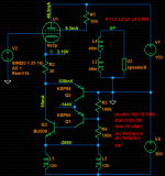
Well, here's what I came up with. And it does have the expected gain ...
but ...
we need a high voltage PNP transistor which can withstand the 600V+ voltage swing on the primary of the OPT,
and because to my knowledge such a device does not exist (the best I can find is MJE15035 which has a 350V rating) the transistor has to be a cascoded as well.
Sim and a prototype setup work and they do have the expected gain.
Because I did not have any of those HV PNPs I went for a pseudo darington configuration in the prototype requiring only small signal PNPs KSP94 (rated 400V) and a good old horizontal output NPN (BU508, C5251) which are good for a kV or so.
And because I did not have a suitable OPT as well, I used a pair of small 12K : 4 OPTs with series connected secondaries and parallel primaries for a 6K : 8 mockup.
Still works and plays load enough from line signals.
In my sim I get 2.7W into a speaker load with just 1.35V peak input and 1 ... 1.5 % THD depending on tube model.
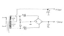
Power supply has +150V and -300V and was derived from a center tapped 115V + 115V isolation transformer.
So where's the catch ?
Well, there's more than one:
Schematics attached, LTspice files and models in the Zip.
One question which I am not able to answer, maybe someone can teach me:
Spud amps using only one single tube, (single stage, no combo), have a problem that the gain of the tube - triode in particular - is not high enough to get any significant output into a speaker from common line input signals. This is usually delt with using an input transformer.
When I saw the Inverted Cascode on the TubeCad site https://tubecad.com/2016/04/17/Triode-PNP Cascode.png I wondered whether this could be translated to a spud solving the gain problem.
In such a cascode the voltage gain is no longer determined by the mu of the triode but solely by gm of the tube and the load impedance, g = gm * R.
Say we used a 6E5P (gm 30 mA/V) into a 6K : 8 transformer (turns ratio 27) the overall gain would be (30 * 6 / 27 = 6.6), so we could get 6 Volts out into the speaker for every Volt input.
In a conventional grounded cathode setup the 6E5P (mu of 30) could only deliver one volt out per volt in.
With the cascode we get 6 times more ... gain problem solved ... or not ...
Well, here's what I came up with. And it does have the expected gain ...
but ...
we need a high voltage PNP transistor which can withstand the 600V+ voltage swing on the primary of the OPT,
and because to my knowledge such a device does not exist (the best I can find is MJE15035 which has a 350V rating) the transistor has to be a cascoded as well.
Sim and a prototype setup work and they do have the expected gain.
Because I did not have any of those HV PNPs I went for a pseudo darington configuration in the prototype requiring only small signal PNPs KSP94 (rated 400V) and a good old horizontal output NPN (BU508, C5251) which are good for a kV or so.
And because I did not have a suitable OPT as well, I used a pair of small 12K : 4 OPTs with series connected secondaries and parallel primaries for a 6K : 8 mockup.
Still works and plays load enough from line signals.
In my sim I get 2.7W into a speaker load with just 1.35V peak input and 1 ... 1.5 % THD depending on tube model.
Power supply has +150V and -300V and was derived from a center tapped 115V + 115V isolation transformer.
So where's the catch ?
Well, there's more than one:
- cascodes have high output impedance and this is no exception; in other words: damping is practically non existing,; sound depends on speakers whether they like "current drive" or not
- cascodes have poor PSR; but only the +150V rail requires good filtering, the -300V rail is almost immune to ripple.
- the carbon footprint is abominable; for 10W burned in the tube there is 20W wasted in the transistor ... and it would be a pain in the neck to get rid of those 40W in an actual stereo build.
Schematics attached, LTspice files and models in the Zip.
One question which I am not able to answer, maybe someone can teach me:
- is the transistor cascode still a cascode or is it soehow involved as an amplifier ?
- the question came up because of how the biasing resistors connect to the output signal ... ???
Attachments

1. A cascode is an acronym for CASCaded TriODES, so nothing having transistors and pentodes is a true cascode.
2. A cascode is also called "Grounded cathode-grounded grid" amplifier, your is a cathode follower and common base BJT.
Very far from cascode idea.
2. A cascode is also called "Grounded cathode-grounded grid" amplifier, your is a cathode follower and common base BJT.
Very far from cascode idea.
Acronym? I don't think that is true? Evidence?A cascode is an acronym for CASCaded TriODES, so nothing having transistors and pentodes is a true cascode.
Cascode sure starts in vacuum-tube days. I can't find a authoritative "it starts here!" reference. It's not in Spangenberg or Reich.
It is mentioned in passing in Radiotron 4th and linked to Wireless World 1948+:
https://worldradiohistory.com/UK/Wireless-World/40s/Wireless-World-1948-07.pdf (page 41 in 6MB PDF)
https://worldradiohistory.com/UK/Wireless-World/40s/Wireless-World-1949-02.pdf (page 46 in 7MB PDF) (this issue also has the James tone control)
The July article is not the cascode I remember: here both grids are driven. The February article is the usual cascode and cites-
H. Wallman, A. B. Macnee and C. P. Gadsden, Proc: I.R.E., June, 1948, Vol. 36, No. 6, page 700
https://worldradiohistory.com/Archive-IRE/40s/IRE-1948-06.pdf (page 38 of 20MB PDF)
The Wallman paper only speaks of triodes and pentodes, of course. Wallman actually worked in WWII and the 'modern' transistor was still being birthed when he published. Like much literature, the cascode is described as pentode gain with triode noise.
And low-noise is off-topic in Power amps, which seems to be the topic here?
The later transistor workers sure were ready to use the "cascode" word as soon as they could afford two transistors. The advantages are somewhat different.
I wonder if @Nelson Pass has history thoughts or if I am annoying him?
"Nelson Pass ..is a student of the history of solid-state amplifier design.." (link)
Looks like you are using the tube for unity gain and therefore require a 300 v pp input signal.
The unequal supplies should then be 200v each to minimize clipping.
The unequal supplies should then be 200v each to minimize clipping.
Cascode was designed by Henry Wallman to be low noise amplifier. I have his book. There is surrounded by several configurations between two triodes and lots of maths difficult to follow nowadays for me.
The denomination cascode is more recent. He called originaly "grounded grid driven grounded cathode amplifier":
https://www.pearl-hifi.com/06_Lit_Archive/14_Books_Tech_Papers/Valley-Wallman/Valley_and_Wallman.pdf
The denomination cascode is more recent. He called originaly "grounded grid driven grounded cathode amplifier":
https://www.pearl-hifi.com/06_Lit_Archive/14_Books_Tech_Papers/Valley-Wallman/Valley_and_Wallman.pdf
Last edited:
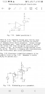
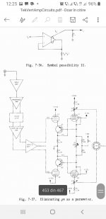
There's a much better version used by Tektronix.I can also make for a fine electrostatic headphones amplifier and you don't need too high voltage transistors either.At the time they used this circuit there was no high voltage transistor anyway...
Attachments
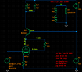
Oh, ... and it can be done the more traditional "Cascode" style as well.
Same gain, same drawbacks, less controversial maybe, fewer parts anyway.
Correct me if I'm wrong:
In the traditional Cascode the grounded cathode triode acts as a transconductance amplifier, turning signal voltage on the grid to signal current at the plate. Neither cathode nor plate move significantly with signal (especially in case of a transistor as a grounded base device in the middle).
The grounded grid triode is but a pass device for the plate current (representing the signal) to the load resistor.
The load resistor translates the signal current back to a voltage.
Voltage gain is transconductance of the bottom triode times the load resistance, G = gm * RL.
Neither the mu of either triodes nor the gm of the top triode are part of the equation.
Probably too simple ... ?
Attachments
Yes. The cascode has a resemblance with pentodes. But tetrodes and pentodes has a kind of noise called partition noise not present in triodes: electrons flowing from grid to anode space, must "decide" if going to plate or screen, both positive respect to cathode. This noise is elliminated in the cascode because upper grid although positive respect to ground, is negative from its own cathode, at same potential as bottom plate. Thus collects no electrons, or almost several orders of magnitude less. But as usually top grid is grounded to signal, it retains its shielding effect between bottom (signal) grid and top plate as in pentodes. Note that I am referring to classical DC series coupled cascoded, but existed some other not so common variations of cascodes still with same properties.
Also, as the output impedance may very high approaching at low frequencies mu squared times anode resistance, it helped maintain high Q in tuned plate circuits in the era of which them were used as RF amplifiers in TV tuners for VHF receivers.
Also, as the output impedance may very high approaching at low frequencies mu squared times anode resistance, it helped maintain high Q in tuned plate circuits in the era of which them were used as RF amplifiers in TV tuners for VHF receivers.
Yes. There is actually a number Mu(1)*Mu(2) as the equivalent amplification factor. And interestingly a 12AU7 gives Mu(cascode) of 400, which is spot-on the number quoted for early Pentodes (before they stopped giving pentode Mu, because you can't realize it in practical design)....Neither the mu of either triodes {is} ....part of the equation. Probably too simple ... ?
- Home
- Amplifiers
- Tubes / Valves
- Spud Inverted Cascode Hybrid Experiment