Does anyone have a diagram of remote turn on circuit (5v) or know which ic (part #)converts 12v to 5v .... I'm only getting 2.5v on my 5v circuit. All my power supply transistors test good output also tests good.. amp looks brand new inside.Any help would be greatly appreciated. Taramps smart 3k..
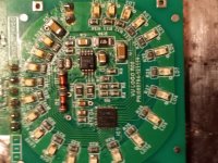
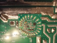
On the in terminal of the led smart control I have exactly 2.53vdc ....at +vcc 1.42vdc ....on my power supply transistors I have 12.31vdc center pins ...on output transistors I have 2.49vdc on outer pins........ic1 on my smart led looks to have a hole in it ill attach picture....If you know what the 5v line is, follow it back away from the controller IC.
Exactly 2.5v?
Attachments
When I apply power only thing that happens is fans turn on they are receiving 6.29vdc
On the in terminal of the led smart control I have exactly 2.53vdc ....at +vcc 1.42vdc ....on my power supply transistors I have 12.31vdc center pins ...on output transistors I have 2.49vdc on outer pins........ic1 on my smart led looks to have a hole in it
If you're going to post an image, do so with a still image with the components in focus and no flare from the lighting. You may have to take several photos from various angles to get what you need.
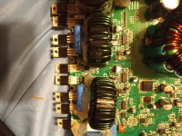
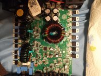
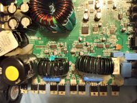
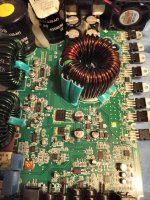
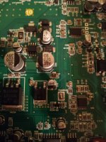
Post an image of the components side of the main board.
Post an image of the components side of the main board.
I apologize video was mispost on my part...
If you're going to post an image, do so with a still image with the components in focus and no flare from the lighting. You may have to take several photos from various angles to get what you need.
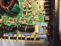
Post an image of the components side of the main board.
Attachments

If you're going to post an image, do so with a still image with the components in focus and no flare from the lighting. You may have to take several photos from various angles to get what you need.
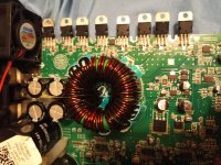
Post an image of the components side of the main board.
Attachments
If you're going to post an image, do so with a still image with the components in focus and no flare from the lighting. You may have to take several photos from various angles to get what you need.
Post an image of the components side of the main board.
Attachments
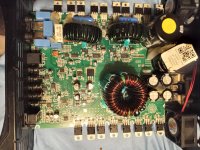
What's the DC voltage on pin 20(?, the last pin) of MC1?
What's the part number on the face of MC1?
What's the part number on the face of MC1?
Thank you so much by the wayIf you're going to post an image, do so with a still image with the components in focus and no flare from the lighting. You may have to take several photos from various angles to get what you need.
Post an image of the components side of the main board.
Attachments

Yes sorry I'm having awful time reading it can read all others ...the voltage is 1.34vdc ....might have to remove to read ....83003?3??........crn935???Did you see post #9?
Are you sure you're on pin 20?
I could be wrong. The supply pin may be pin 1.
The number should be something like 16F1829.
I could be wrong. The supply pin may be pin 1.
The number should be something like 16F1829.
Yes sorry I'm having awful time reading it can read all others ...the voltage is 1.34vdc ....might have to remove to read ....83003?3??........crn935??
CRN935RRY or can935rry....83003f3p6...gonna try and look em up see if either correct its e tremely faded all others are readable I apologizeYes sorry I'm having awful time reading it can read all others ...the voltage is 1.34vdc ....might have to remove to read ....83003?3??........crn935???
Pin 20 is 1.71 .... pin 1 is directly left 0.631vdc ... my mc1 is unreadable I'm emailing taramps now i will have to post part # tomorrow when they respond ....
unfortunately they don't disclose any of the smart line schematics, not even to authorized service centers,
in my case they sent a brand new replacement board
in my case they sent a brand new replacement board
Thank you for the info ultra ... taramps had sent me info for bass8k before but they have ignored My smart3 info requests so far
- Home
- General Interest
- Car Audio
- Taramps Smart 3k 5v issue