Why did this EL84 not work in my Decware amp?

I bought 2 sets (4 total tubes) of these to add some variety to my tube collection:

Ei 6BQ5 / EL84 – Upscale Audio

I have a Decware UFO2 and it is compatible with EL84s, and I have used other EL84 tubes in it, no issue, this amp begs for tube rolling.

The ones in the link arrived in the mail, popped them in, and the volume was MAYBE 5% what it should have been, and what was there was muffled and muddy (100% useless, there was just 'something' barely playing). Tried the other two, same thing. Long story short, either they are not compatible or they all happen to be defective.

Any idea? Why would they fit, properly heat up (heaters came on as expected), play 'something' but not work? No biasing in the amp...and they work fine with a range of EL84s.

They will be going back tomorrow, but now I have zero confidence in buying other EL84s because I have no idea what was happening.

Thanks!

Behringer DJX750 transformer replacement

Hi there,
the transformer on my Behringer DJX750 mixer died and I'm looking for a replacement.

However, I couldn't find a off the shelf replacement. Perhaps someone might have an idea where I can source a new transformer from.

Specs are the following: 32W with a +19V, 0V -19V and a second 12V output (so, something like + and - 6V)

Most of the transformers advertised on aliexpress only feature the 19V rail and I can't seem to find one that supplys the other rail as well.

Thank you for your help

Help needed with my Marantz PM17 MkII

Hello, I need your help please. I've had several problems with my Marantz PM17 mkII for some time now which appear for a few minutes after switching it on: several slight bumps and a strong one on the speakers, delays in activating the input relays, the thermometer pointer remaining at 0; after everything has warmed up a bit everything returns to normal, except that if I 'knock' on the chassis I hear a corresponding slight bump on the speakers.
I opened the device and I understood that the area sensitive to the 'knocking' is the secondary power supply area (+ - 22 volts) at the top left looking at it from above, where there are two 1800 uF/50 volt electrolytics and various transistors/ic on heatsinks, two of which get hot enough to be difficult to touch for more than a few seconds.
If I 'knock' in this area, on heatsinks, electrolytics, connectors and neighbours, I hear the bumps on the speakers and I see the thermometer pointer falling to zero or recovering. The connectors are solid, it seems a matter of some component. In addition, at the foot of the electrolytics there is a white substance but I'm almost sure it's glue for fixing them because it's very tough at touch.
Has anyone had a similar experience and can advise me on what to replace (with my limited DIY and related measurement skills)?
Here's a photo made during replacing of output protection relay assuming the problems came from there, but that's only partially because all problems mentioned at the beginning remained and probably increased:
PM17 open.jpg
Thank you very much.

SDA Bypass caps and other snakeoil remedies....

having inherited a set of polk Sda 1b's, I decided to optimize.
I am a full-range guy at heart, the simpler the x over the better...
Everything I have read about the 1b x-over says that the bypass caps are not needed,
The explanation I remember is that the modern 4.7uf cap is "fast enough".
Is not the speed of the cap tied to the voltage frequency or the audio frequency?
To my understanding the signal is going around the cap,not thru it.
I am by no means an expert, I have a Electronics home study course by Heath, with the
breadboard,,,,a raw beginner at 71.
Even though i have been tinkering for 56 of these 71 years.
Just wondering.....thanks for comments.....
to bypas or not to bypass....

Damping factor

Anyone dispute this ?

Damping Factor =Zload/Zamp

Zload = speaker impedance
Zamp = output impedance of amplifier

Is the output impedance of the class ab amplifier a
constant, ie restistive measure or is
there any AC components which would
cause the output impedance to be a variable?

On a typical class ab amplifier, if you were
to trace the path that contribute to output impedance,
what components are those? ie, speaker terminal --> output
coil --> output stage transistor w/associated series resistor + what else?

Worth replacing film caps in a Haffler DH220?

After putting a dh220 on the shelf forthe last 8 years (time flies!), I finally have it on the bench.

I went through and compared each cap to what is om the components list and all but one are as specified on terms on capacitance. Some are a higher voltage than specified.

Some of the caps are branded (Nichon, IC, Evox), but most of the film caps aren't.

I've read that film caps don't generally degrade, but gicen they aren't branded, I question the quality of them and am on the fence as to whether ot not I should replace them.

Also, I am going throigh and testing the volatges at each transistor per the manual, and they seem a bit off. I need to make a table of all the values and will post them when I'm done. I wasn't able to find voltages for the test points
on the board. Some are the same potential as the transitor leads, but at least one isn't. If anyone knows what voltage those points should be, I'd appreciate that info.

Thanks
James

Soundstream D200

Could use a little help (maybe point me to the correct Amp forum 🙂)

I inherited the Soundstream D200. By default its dual mono, but supports bridged (which is what I want to do, gonna drive a single sub). The pdf that I found on the web basically says "send it to soundstream for a minor internal modification". I am hoping someone knows what that modification would be 🙂

For that matter, its possible the amp is already configured that way... but I wouldn't be sure how to check.

Horrible pictures of insides from the web if that helps:
http://ampguts.realmofexcursion.com/Soundstream_D200/inside1.jpg

I am happy to open mine up and take a good pic though.

Rockford BD1000.1 amp issue

Hello everyone,
I have a question about my Rockford bd1000.1 amp I have, it is still working but does have a lower power output. I took the amp apart and I did find one of the semi conductors is cracked and on the back side of the board it did get a little burnt. The question I have is, I can repair the board and obviously solder in a new conductor, but can I purchase just one, or will I have to do the whole row? part# 5n05HD is showing they're discontinued, but I am finding a replacement for it. Any help would be appreciated.

IMG-4626.jpg

Sony STR D390 delay turn on one channel, easy fix?

My neighbor is the original owner (>20yrs) and recently noticed brief delay (2-3 sec) starting on one channel when first turned on. Frequently turning on the volume higher seems to cure the problem during (silent period). Once working sound seems fine even when the volume knob is near mute. During brief delay sometime brief static is also audible. There is no obvious static when working with volume knob. Is there a possible simple fix for this?

A little tester to determine transformer PhaseDots with no scope or signal generator

2022 JUNE 09 -- SOLD OUT (YOU CAN STILL SEND THE GERBERS TO A PCB FAB AND BUY BOARDS YOURSELF)


Transformer schematics include "Phase Dots" that indicate which ends of the windings are in phase. Unfortunately, many transformers in used equipment are not marked with phase dots, and quite a few new transformers are not marked either.

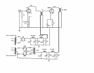
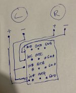
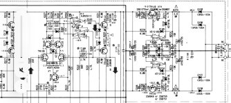
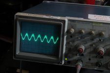
If you have a signal generator and an oscilloscope, it's easy to determine the phase dots: see the first picture. If scope channel2 is "right side up" compared to channel1 then winding2 is in phase with winding1, and "?" becomes a dot. And vice versa. However, some DIYers don't have a signal generator and a scope, so this little tester board called "PhaseDots" might help.

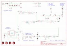
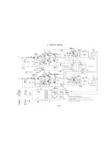
It operates on the same principle, but instead of a scope and human eyeballs, the circuit uses a phase detector (XOR gate) to decide whether the windings are in phase or out of phase. This lights up either a Green LED (in phase) or a Red LED (out of phase). Simple and unambiguous. The circuit schematic is picture#2.

A 555 timer/oscillator drives a square wave into transformer winding#1. The resulting waveform on winding#2 is amplified in a series of CMOS logic inverters (gain > 5x per stage) and compared in XOR gate U1C. If they're in phase, D4 lights up. If not, D3 lights up. RC pulse shapers with slow risetime and fast falltime, drive the LEDs.

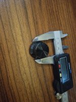
In practice the tester board is simple to use. Connect one of the transformer's primary windings to connector P2 (labeled WINDING_1) and leave it connected. Then, one by one, connect all the other windings to connector P3 (labeled WINDING_2) and observe their dots. Write these on a schematic as you go. After the last winding: Boom, you're done!

It is important that the PhaseDots tester should always drive a transformer primary winding. (I.e. always connect a primary winding to WINDING_1). Why? Because transformer primary windings have sufficiently high self-inductance to ensure a long (L/R) timeconstant. This prevents the winding from behaving as a differentiator, ruining the input waveform and lighting up the wrong LED (or both LEDs).

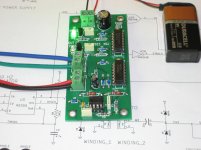
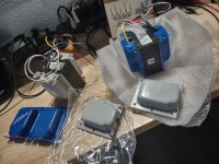
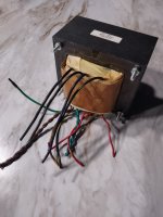
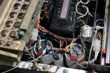
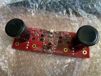
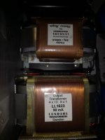
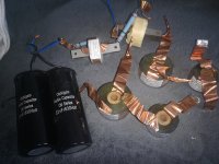
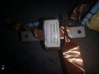
Picture 3 attached, shows the PhaseDots tester connected to an Antek AS-2222 toroidal transformer. Red and black are a primary winding, blue and green are a secondary winding. The illuminated green LED tells us that if red has a Phase Dot, then so does blue.

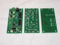
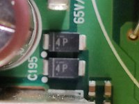
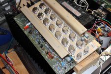
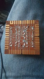
A few other pictures are attached, showing the PCB that I laid out. There's also a set of Gerber files that anyone can send to a PCB fab (I recommend PCBshopper.com to help you choose a fab) and have their own boards made. The Gerber files are included in a zip archive, along with a Bill Of Materials and other ancillary stuff.

I built several PhaseDots boards for my own use, but I've got some leftover boards and leftover kits of parts which I am willing to let other DIY hobbyists have at my cost.
PCB only: {$6 ship to USA} {$9 ship to CAN+MEX} {$12 ship to rest of world}​
PCB + kit of all parts: {$13 ship to USA} {$16 ship to CAN+MEX} {$22 ship to rest of world}​
However, I will only accept cash or checks. Fortunately I will accept a check drawn on a non-USA-bank and denominated in non-USA-currency.

Sorry, I will not accept PayPal. I will not accept wire transfers. I will not accept Western Union. If you want to set up a little re-distributorship that does accept these, so you can forward boards and kits to other DIYers, please go right ahead with my blessings and good wishes.

Anybody who wants a board or a board + kit of all parts, send me a Private Message ("send me a PM") for purchasing information, mailing address, etc. I've got approximately twenty of them to get rid of.

Hope you enjoy the PhaseDots tester!

2022 JUNE 09 -- SOLD OUT (YOU CAN STILL SEND THE GERBERS TO A PCB FAB AND BUY BOARDS YOURSELF)

Attachments

  • PhaseDots_Principle_of_Operation.png
    PhaseDots_Principle_of_Operation.png
    10 KB · Views: 2,826
  • PhaseDots_schematic.png
    PhaseDots_schematic.png
    37.9 KB · Views: 2,738
  • PhaseDots_In_Operation.jpg
    PhaseDots_In_Operation.jpg
    423.4 KB · Views: 2,675
  • PCB_photo.jpg
    PCB_photo.jpg
    505.3 KB · Views: 2,448
  • front.png
    front.png
    32.6 KB · Views: 2,342
  • back.png
    back.png
    31.4 KB · Views: 1,065
  • PhaseDots_Gerbers_and_Everything_Else.zip
    PhaseDots_Gerbers_and_Everything_Else.zip
    171.4 KB · Views: 533

My web site wa2ise.com should now be secure

But you may need to type out https://www.wa2ise.com/ to make it secure.

I think I have redirection active, so www.wa2ise.com should land you at a secure place.

I found that my hosting company Turbify https://www.turbify.com/ (who comes up with these names...)
bought the company that hosted me before.

As far as I can tell, I have my web pages with SSL security. It was an option I had to enable, at (I think) no extra cost.

Then I had to edit some of my links to make them go to https so they'd be secure.

I mention this as someone may want to look at my page https://www.wa2ise.com/netcom/SCA 35 modifications.html
about SCA36 mods I did. Or various 3f4 spice models of vacuum tube you can find links to at
https://www.wa2ise.com/netcom/netcomhomepage.htm
and I have some other stuff on audio you can find hunting around from https://www.wa2ise.com/
  • Like
Reactions: anchorman

Transistor heat sink mounting

Can I mount the thermal monitoring transistor, can't think of the name, that sits between the two power transistors directly on one of the power transistors, or behind on the same mounting screw?
I have NO WAY to mount it between them, they have their own separate aluminum rail.
I could place a short piece of flat bar between the power MOSFETs and mount it in the middle. Just there will be three junctions that will require screws and thermal paste.
The designer said to just mount it on one of the power MOSFETs.
And which MOSFET,the positive or the negative?
Are they THAT critical I never crank it up, just like plenty of head room.
He has one smaller watt with out thermal run away and doesn't use it, but will need to replace the 40-0-40 to a 30-0-30.
Thanks

Help with XLR balanced potentiometer

I‘m trying to wire out the balanced inputs of my KGSSHV amp to a quad ALPS pot but I’m confused on how to do this right.

I’ve attached a schematic. I take +/- of each XLR input and wire for instance + to Input A, - to Input B of the ALPS pot. The output goes to OUTA, OUTB respectively.

Problem is I get a full signal out but I’m unable to attenuate the volume so there must be a thinking mistake on my side.

Do you know where I might be going wrong?

Attachments

  • DB162ECC-12F2-43B1-804C-A45945130A87.jpeg
    DB162ECC-12F2-43B1-804C-A45945130A87.jpeg
    397.8 KB · Views: 249

Disclaimer I'm no audiophile, I just like to measure stuff

Feel lost when you sit around with your audiophile friends and they talk about this transistor gives you better high freq responce. Or this one gives you better mids. Or this chip amp has more warmth than that chip amp.
Im a guy who just likes to measure stuff. So have some doubts.
Its there a way to measure stuff like warmth of an amp,
As far as Im concerned and with the limited few amps I have put together. I like to just measure the output. In most cases so far I see that I have a flat response curve. i.e. feed it a 1 volt peak to peak signal from all freq from 20Hz to 20Khz. And Im happy when I see that the output curve out of the amp is flat. Sometimes Ill just do a Channel 1 - Channel 2. And if the curve is flat with no distortion call it a day.
Have read up as much as I can. And am still confused. When audiophiles are talking about differences in amps. Are they purely talking about stuff that can be measured or is there a component of stuff that cant be measured. Or am I just not measuring the right things the right way ?. Or is the magic in the imperfections which cant be measured ?.

Help Find Crossover Point Based ON Directivity

PEERLESS / VIFA BC25TG15
DAYTON DC160

I have these two drivers and would like to know the best crossover point based on directivity? Or if anyone had a polar plot for the tweeter and off axis measurements on the woofer so I can decide for myself? This would be ideal but I am open for recommendations.

I will be using this speaker with DSP so I am not too fussed about other variables and it will be a cheap little speaker so if I could get a crossover point that is decent enough based on a harmonous directivity that would be greatly appreciated.

ShibaSoku Automatic Distortion Analyzer

I thought that it was time to start a new thread for the ShibaSoku Distortion Analyzer. I have reverse engineered part of an AD725C and have attached some schematics. I am in work at the moment so time is limited which is my excuse for the messy schematics. I can't guarantee the accuracy.
The equipment is old school and I think that a better way to go is to use a Sound Card preceeded by a Notch Filter as recommended elsewhere.

Attachments

Car audio install question

I have a question on this install .

I have a 4 channel DD audio amp 4x100 @4ohm and 160x4@2 ohm

I have 2 6.5” and 2 8” speakers in the door these the speakers in the door are not really for midbass they were designed to play loud between 100hz amd 8khz both speakers pretty much have the same specs .

I was gonna add 2 more speakers (midbass) to the lock panels so I can get some mid bass upfront .

Wondering can I use the 4 channel and bridge 2 of the channels to the 6.5” and the 8” in each door and then use the other 2 channels for the midbass drivers . This way I can set the crossovers how I want them .

Or would it be wiser to get another amp to run the mid bass drivers alone and use the 4 speakers I already have on the 4 channel and not bridge 2 of the channels

Minimserver, Synology NAS with external usb disk problem

I have a Synology DS261j NAS. It is connected via network to DAC Gustard R26 which has an internal streamer.
A 3 TB USB drive is connected to the NAS.
I play through MinimServer which is installed on the NAS, controlled with BubbleUPNP mobile app.
However, MinimServer does not see the external USB drive. It only sees disks on the NAS. Is there any way to set the MinimServer to see the USB drive?
The disk is visible in the Synology file manager application, and Roon can see it on another computer, as well as on the network.

Second question: The sound is great. However, DSD files and PCM HiRes interrupt a lot. I guess the CPU in the NAS is too weak.
Which Synology NAS would be powerful enough to play DSD and PCM HiRes files?

Toshiba SC330

Hello,

I have bought this amp in the past first of starting with class a amplification. It was bought used and I enjoyed the sound for a while.
Unfortunately one of the channels didn’t have the original output bjts and the replacements(some bd’s) failed when the amp was at me.
I replaced them once(with same bd’s) then(the same time I finished my aj) the outputs failed again so I abandoned it in the garage.
For many years I thought that I lost it somewhere and now recently searching for something else I found the amp.

One channel still has the original output bjts.

What can I use as replacement for the originals? Or maybe someone that has a few around and can sell?

Thanks.

Attachments

  • 5AF40C95-2C38-40A6-BA8A-65DC5B2BDB67.jpeg
    5AF40C95-2C38-40A6-BA8A-65DC5B2BDB67.jpeg
    210.8 KB · Views: 83

SE driver slew-rate: suggestions welcome

Hi,

for a SE amp I need to drive a 27 pF load at around 180 Vpp.
Considering 20 kHz as a target frequency, it is needed 610 uA to drive it.

I would like to use a bootstrapped 12AX7 as a driver mainly because of its mu=100 and good linearity.
Is it acceptable for slew-rate paralleling two 12AX7 at around 2,5-3 mA total? Any better solution?

Thanks in advance,
Roberto

Yamaha C85 Problem

Hi Guys, I would like to know if some of you knowledgeable guys could run your eyes over this attachment and see if anything obvious jumps out at you.
It is 14db gain stage of a Yamaha C85 Preamp which I am trying to upgrade.
In fact I upgraded it some time ago, but it had been put aside while I used some of my other preamps. The fault with it only came to light when I started using another Power Amplifier, a Harman Kardon Citation 22. After carrying out several trips back to the workshop(Overheating output stage), I discovered it was not the power amp at all.The Preamp was suffering from HF oscillation and I presume due to the wide bandwidth of the power amplifier, said HF was being amplified enough for heatsinks to get red hot.
I've since returned preamp to the bench and removed the ICs that I had upgraded to in this stage, an OPA1656, and replaced it with the only SIL opamps I had knocking about, JRC5532 and oscillations disappeared. I then still in search of improving performance , replaced these with opa2209, and checked and refined decoupling caps positioning and routing, 10uf + 0.1 sat directly on PSU pins and down to a chunky piece of local ground plane.I thought with the reduced speed of these opamps all would be well. On checking the output waveform, the obvious oscillating trace had all but disappeared, but I did however note that with the volume control at full max, there was still some sign of oscillation, but decided that as unlikely to have volume hard on, all would be well. After returning preamp to system and sitting down for a good listen, all seemed well, but on leaving room and returning 15 minutes later, found one channel on power amplifier had overheated and shut down again. Both heatsinks were uncomfortably hot, so looks like there is still enough HF being output from pre to upset the power amp.
I will shortly be returning preamp to the bench for further investigation, but thought I'd put it out there for any suggestions to address this problem?

Attachments

  • Screenshot_2023-03-27-15-43-21-76_e2d5b3f32b79de1d45acd1fad96fbb0f.jpg
    Screenshot_2023-03-27-15-43-21-76_e2d5b3f32b79de1d45acd1fad96fbb0f.jpg
    268.3 KB · Views: 114

miniDSP question

I have a few questions about using a minidsp instead of a passive crossover.

It looks like the minidsp 2x4 will replace both crossovers so is the only downside needing two amplifiers? will it sound as good as the passive crossover? Can the amps be different 120w a a/b amp for the woof and a class d amp or a 30w amp for the tweets? the minidsp kit costs about $200 I read the data sheet so what am I missing?

Unique 8-Channel Standalone DAC Project

Hey All,

After extensive research, talking to engineering nerd friends, and general hair-pulling, I'm here for advice.

My project is a standalone, 8-channel (octophonic) sound source; audio read from files stored internally or read off a disk.
Signal path is: WAV from flash memory->8-channel DAC->8 channels of amplification->speakers
Essentially, user presses a button to play, and controls gain of four stereo pairs that play in sync.

I have seen an 8-channel player on the market, used mainly for art installations, that looks just like what I'm trying to do in terms of DAC. It's called a Waveplayer8: http://www.waveplayer-systems.com/
I'm guessing the quality with that isn't great, but the quality for this project doesn't have to be, either. I'm fine with 16-bit sound. While I could just try to track one down, I'd much prefer making something more customized and understanding the signal flow.

I'm guessing there are projects like this out there, but I've been unable to find them.

Starting really small, with about 3w per channel, I'm looking at something like this:

  1. Power supply:
  • AC-to-DC power supply
  • Voltage regulator
  1. Microcontroller:
  • ADAU1452 digital signal processor with integrated sigma-delta DACs (one per channel)
  • Crystal oscillator for generating the master clock signal for the DSP
  • I2C interface for communication with external devices, such as an SD card reader
  1. Memory storage:
  • SD card slot for storing the 8-channel sound file
  • Voltage level shifter to convert the 3.3V I/O signals of the SD card to the 5V logic level of the ADAU1452
  • Pull-up resistors for the I2C interface
  1. Audio output:
  • 8 output buffers with a gain of 1 (one per channel)
  • Output coupling capacitors to remove DC offset from the signal
  • Output connectors to connect the analog signals to the amplifiers/speakers

For context, this is my first time building anything more complicated than a condenser mic. Any advice would be very much appreciated, large or small.

Budget friendly dual(?) supply for DIY FE 2022 and MoFo

Hi folks,

Looking for ideas on the following.
I want to build a desktop system and envisage a pair of powered speakers to minimise wires, connections, enclosures etc. The main heatsink limits me to about 35W of heat so the choke loaded Mofo seems like a good/efficient choice. So assuming a 24V supply, I would be looking at ~1.5A through the MoFo. I anticipate a power supply capable of providing 3A to leave some headroom.
I plan on using the DIY FE2022 and want to build in some voltage headroom here too.
So the question is the power supply...
I could use two Meanwell SMPS supplies on each side to give 24VDC for the Mofo and 36 or 48V for the DIY FE2022. But I hope that there might be a more elegant solution that is relatively cheap and Noobie friendly to generate low power 30-48V for the preamp from the MoFo supply. In an ideal world I'd like to run the whole lot from a 24v laptop supply or similar. I'd really like just the RCA and power cable going into the box and not mess with mains AC.
So the question is how to get enough voltage swing from the front end/power supply.
As always, your thoughts and guidance are appreciate,
TIA.

Stabilizing Bose 1801

I'm working on restoring a Bose 1801. I've replaced electrolytic caps, opamp, carbon comp resistors, main caps, and added DC protection.

I'm having a stability issue in one channel. This is shown in the pictures. It starts happening at very low power. I was talking to Leestereo and he suggested playing with the value of the phase capacitor C8. It is 200pf originally. Raising it made things way worse but lowering it to 100pf solved the issue but destroyed the square wave performance. I don't have any values between 100 and 200 on hand. I tried a new 200pf cap and it had the same issue as the original.
I've had this issue 2 other times and one time I had to raise the value of the VAS cap. The other time it was the resistor in the output network, I don't know what it is called. R47 does that job in this amp.

I've attached the schematic.

Attachments

  • IMG_9457.jpg
    IMG_9457.jpg
    1,008.4 KB · Views: 926
  • IMG_9455.jpg
    IMG_9455.jpg
    843.6 KB · Views: 602
  • IMG_9459.jpg
    IMG_9459.jpg
    1 MB · Views: 1,116
  • 1801schematic.pdf
    1801schematic.pdf
    88.2 KB · Views: 251

Boom or Bust - scaled down subwoofer design series submission

'Barevids' Sam on Youtube is doing an interesting video series where scaled-down 2" micro-subwoofers get 3D printed and testing inside a model automobile, to compare different enclosures. The fun part (IMO) is that when filmed at a high frame rate with sped up real-world music, the final videos can be played back slowed down by 6x, and they look and sound exactly like a 12" subwoofer playing normal bass.

Testing is done at 4 frequencies (power or excursion limited, determined separately for each tone), 150hz, 198hz, 270hz, and 360hz (corresponding to scaled frequencies of 25hz, 33hz, 45hz, and 60hz).

At this time none of the submissions take advantage of boost the output of both sides of the cone (e.g. 6th order bandpass), they are all either reflex variants or 4th order bandpass as far as I can tell (one seems to be BP4 with horn loading on the output). So I designed and submitted a simple 6th order parallel bandpass and it may get shown! Here is the bulk of my submission:

I've designed a a large 6th order parallel bandpass box using winISD and Sketchup. I am using Sketchup Make 2017, which I had assumed was 'v17', but didn't see any way to export to STL. DAE and SKP are attached. Happy to save to older versions of Sketchup if needed, or download an older version that can export STL.
mini1.PNGmini2.PNGmini3.PNG
It's designed to be as loud as possible while minimizing excursion across the test bandwidth as much as possible. The back chamber is about 2/3 of a liter tuned to ~155hz, the front chamber is about a half liter tuned to ~360hz. It should perform very much like a vented box made of just the back part for the lowest two notes; no excursion problems at 150hz, possible excursion problems at 198hz (exactly the same as my best effort basic vented box design, fwiw). Then it should start getting some boost at 270hz from the front resonator, then get a massive boost at 360hz. Attached winISD graphs are shown at 10 watts.

Outside dimensions are 182mm x 108mm x 78mm, with 4mm walls. By definition it has to be a two part box; one end is the access panel panel which should slide in nice and tight. Its double thick since it isn't easily braced; half of it is designed to slide inside the main box. I don't know how to seal it such that it will still be removable! I also don't know how hard it will be to secure the woofer in place inside the box, and I didn't put in any reinforced points for mounting screws. The magnet is designed to go into the rear chamber (away from you when installing), though the tolerances are probably not tight enough to matter.

I've never worked with a 3d printer before so I don't know if my design is even printable. Everything should be supported from below except the rear chamber port tube, which runs parallel to the bottom without anything under it. Please let me know if I need to redraw that!
1 spl.PNG3 excursion.PNG2 impedance.PNG

Response:
Hey Chompy! Ahh this looks brilliant! I look forward to doing this one! Ill have a play around with it if needbe in sketchup to get it to print well, i think it looks okay as is but ill have a closer look nearer the time of printing 🙂 Thanks for the submission!
Sam

I also tried designing a large simple reflex, but it ended up being identical to the back half of the above BP6, with no advantages for these test parameters (size isn't penalized for example) so I didn't submit it. Conceptually I think it could be interesting to print a BP6 as a complete vented box with a separate front resonator, and test it both before and after attaching the front part.
I'm fully aware that the inaccuracies of winISD, the scale of this project, and my lack of 3D materials experience may make the entire design a joke; I'm very curious to see the impedance plot of the finished print if it gets used, to see if it correlates. I put some effort into determining the inside volumes of the chambers minus the port tubes before drawing up the enclosure, but the bracing is not really accounted for nor was any end correction made on the lengths of the ports (though the 'middle of the wall' ends should match reasonably with the winISD 0.732 default). Being a 3d print there's no excuse for the ports to not be flared, all edges rounded over, the bracing much fancier, etc, but I'm at the limits of my sketchup skills as it is...

Questions, thoughts? Anyone else want to try? Feel free to post it here if you do!

Here are the test and woofer parameters: https://docs.google.com/document/d/13YayzCsIZ58GIl6czQCEoz9ShTWKgAfU_1n6SGTBByo/

Intro video: Login to view embedded media
Video for how to submit: Login to view embedded media
Episode 1: Login to view embedded media Episode 2: Login to view embedded media Episode 3: Login to view embedded media Episode 4: https://www.youtube.com/watch?v=y7KKPThsA8U
Episode 5: https://www.youtube.com/watch?v=KSvCiuMgGIo
Episode 6: https://www.youtube.com/watch?v=_ws6HA5aXzk

Attachments

  • Like
Reactions: GM

Problem with Marantz CD-40

Hi!

I have old CD player - Maranty CD-40. Actually it is my first CD player. It does not want to play CD's. Cleaning laser did not help.
It does not read disc properly - after long time it was off it did read TOC and displayed track numbers and total timing but it was just for a second.
Usually it is trying to read, making strange noise and nothing. Disc is NOT spinning at all.

YouTube

You can see on this video what is going on.

It seems that electronics is 'confused'. Sometimes even if there is no disc inside it is trying to read and play disc. Can yuu help, please?

For Sale Usher 8948a, Usher 9950-20 and crossover parts

I have for sale a pair of Usher 8948a midwoofers, pair of 9950-20 tweeter and crossover for the following project:
https://diyaudio.pl/forum/praktyczn...-4-10-usher-8948a-9950-20-projekt-by-yoshi_80

All items are still sitting in complete loudpseaker which is not in use. Slightly used for 2 years, mainly for classical and jazz music.

Will consider selling in below options:
1. Whole set (woofers, tweeters, crossover) 400EUR
2. All drivers without crossover 350EUR
3. Woofers and tweeters separately - price to be discussed
4. Can even sell whole loudspeaker if anyone interested, but shipping needs to be discussed.

All prices are negotiable, for person interested in whole set I am open for your price proposal, similar for drivers set.

Shipping within EU is free in given prices (normally it costs 30EUR)

Attachments

  • 20220828_161046.jpg
    20220828_161046.jpg
    372.6 KB · Views: 210
  • 20220828_155547.jpg
    20220828_155547.jpg
    327.2 KB · Views: 217
  • 20220828_154825.jpg
    20220828_154825.jpg
    478 KB · Views: 327
  • 20220828_155147.jpg
    20220828_155147.jpg
    524.6 KB · Views: 188
  • 20220828_161046.jpg
    20220828_161046.jpg
    372.6 KB · Views: 173
  • 20220828_154825.jpg
    20220828_154825.jpg
    478 KB · Views: 149
  • 20220828_155547.jpg
    20220828_155547.jpg
    327.2 KB · Views: 154
  • 20220828_155147.jpg
    20220828_155147.jpg
    524.6 KB · Views: 153

Goldmund PreAmp Discussion

Got some files of Goldmund-style Preamp design, based on Mimesis 27 PreAmplifier.
I have transformed the file to Altium format, also ASCI or so.

The Mimesis 27 uses A20 modules as front-end amplification, but in this way, additional A2 PCBs are required,
so the design shown here cancels the modules, directly place the components on mainboard, which I think is more friendly for DIYers, unless you're pursuing 1:1 Clone.

As for power supply, the filtering capacitors adopt axial design, very iconic for this type of Preamp; it's actually capacitance multiplier, 45-0-45 VAC Input.
The Iconic blue-shell axial capacitors: Vishay BC (Philips) 470uF/63V, 1000uF/63V, 021 Long Life series.

Rifa PEG long life series is also my favorites too.

Haven't decided how and what to share, just started the soldering work.

***Notice:
All information, resources are provided AS IS.
The information shared may or may not contains incorrect, inaccurate contents.
The provider have no any obligation to be responsible for any consequent loss.


1673025950673.png
1673025757096.png


1673026348650.png

1673027239633.png
1673027764880.png


Feedback capacitor: Nichicon MUSES?


1673027333203.png


The PCB produced on the basis of file.

1673025726219.jpeg

Attachments

Varieties of DACs

I think all of the past/present DAC "topologies" are as follows:

(1) Discrete (R2R, etc. Examples: Soekris, Denafrips, etc)

(2) ASIC (single chip, may also have digital filter inside. Delta-Sigma, Bit-stream/MASH, R2R, DEM, CC, etc. Examples: Philips TDA1541, AD1862, PCM63, AKM 4499, ESS9038)

(3) Firmware (FPGA. Example: Chord)

Other:

Parallel ASIC. Examples: Accuphase "multi-multi" ( 4 parallel PCM 63), diy: tda1543 http://www.diyparadise.com/8x1543dac.html)

Anything missing from this list?

Long story but I need help

Hi everyone. I’m new but happy to be here. I have a pair of speakers that I have been working slowly at since college. Started in Electrical engineering and then went into ministry instead. The boxes are very large and custom finished. My grandparents paid for the materials and my uncle built the boxes. My grandparents have since passed and my uncle ‘s Parkinson’s is now advanced to the point he cannot do woodworking any longer. All that to say these cabinets have a lot of sentimental value to me.

the components were…what I could afford at the time. I have acquired in the time since 2 dynaudio d-54-af midrange drivers (someone told me these are excellent midranges) and 2 Peerless XT25TG30-04 tweeters which were also recommended.

I have a grant for a bit of time off from ministry (3 weeks) and funding for a renewal project. I would love to finish these With the new tweeters and midrange.

the cabinets are very large, I had a 12 and a 15 mounted on the front of each. I can’t add dividers if necessary.

what I need is help with woofer and crossover recommendations. I use a Yamaha 150 watt amp. What I want are to make these the feature pieces of a stereo music system. I want as much range as possible, to be able to play them without needing a sub. I want them to sound good and cover a full range so I can enjoy not only the look and the memories but also the music. I see Madisound has faital pro 15” woofers on sale. would those work?

really looking for woofer advice and tips. Thank you all for being willing to help!

Single Module - Firstone Large v1.4 and Hypex SMPS 3kA400

Last items I have remaining out of the FirstOne bundles I have sold recently.

1x Spare FirstOne Large Module (Used) v1.4. £110 (firm)+P&P
1x Hypex SMPS3kA400 2 x 65 VDC 3000w power supply and wiring loom - very little use only around 12 hrs on it. £150 (or nearest offer)+P&P

Items will be available from here until they're sold. UK buyers preferred, but happy to ship anywhere.

Suitable for replacements, or could be used together to power a high fidelity subwoofer.

Thanks.

attachment.php


attachment.php

Attachments

  • IMG_1057.jpg
    IMG_1057.jpg
    1 MB · Views: 357

suggestions for desktop 2-way with OB ribbon top

I have a daughter with good ears and an interest in good sound. We have built a couple of Nelson Pass amplifiers (ACA, ACA Redux and M2) and will continue to explore this aspect, but I am interested in building a pair of desktop speakers that would use a ribbon in open baffle and a woofer in an enclosure or SLOB. Can anyone point me to such designs or threads or make other recommendations?
Many thanks in advance

GB (possible) for TOSHIBA 2SK1530 & 2SJ201 pairs

I have an opportunity to purchase up to 30 pairs of TOSHIBA 2SK1530 & 2SJ201 MOSFET's. They are NOT matched and the price from Tokyo is $60/pair. They are only available as pairs of 2SK1530 & 2SJ201. This is the best price I could find in Tokyo, others wanted $40 - 140 each piece, so $60 a pair still seems high to me.
I don't need nor want 30 pairs, so I thought others might be interested. The price including shipping and PayPal fees from Tokyo to Wisconsin, USA. I would like to keep the group buy only for North America as I've had such problems shipping to G.B. and Europe.
If interested reply to this thread, I'm not overly excited about this purchase due to the cost, so I would gladly join the little to no interest group. However, if there is a demand, then I will put this together.

U frame vs SLOB + wings (a la XSD)

I’m putting together a hybrid OB / horn speaker. I have 8 x AE Dipole 12 woofers to play with, so 4 per side. Current plan for them is a 1.5 arrangement whereby 2 of them are low passed at 100hz, whereas the other 2 are low passed at c. 600hz. This post concerns the 100hz low pass ones. I am thinking I might put each one in a U frame. Alternatively I could put 2 in a SLOB with wings, similar to the configuration XRK used on his XSD speakers.

I’d welcome any thoughts or comments from the OB cognoscenti on the relative merits / disadvantages of these options, or indeed any other suggestions.
  • Like
Reactions: Jazzfan

Thershold 4000 "hydraulic magnetic breaker"

I have a little problem finding the right Magnetic Hydraulic breaker to a couple of Threshold 4000's from -78 and -79.
I have already done a full restoration of blown OPS, but those breakers (that have failed afterwards) seems to be some crappy ones that doesn't live longer than 35 years 😉

Does anyone know specs to look for, or do you know where to find the right ones?

Best regards

Figge

GRS 8FR-8 Full Range Low Budget Project

Have here a nice and cheap pair of GRS 8FR-8 drivers and like to put them in a simple cabinet.

Data sheet GRS 8FR-8:

Resonant frequency fS 39 Hz
Electrical Q QES 0.46
Mechanical Q QMS 2.94
Total Q factor QTS 0.40
Suspension equivalent air volume VAS 64 litres
DC resistance RE 7.02 Ω
Voice coil inductance LE 1.28 mH
Maximum linear excursion Xmax ± 3 mm
Efficiency η₀ 0.81 %
Efficiency bandwidth product EBP 84
Overall diameter 203.2 mm
Baffle hole diameter 184.1 mm
Mounting depth 98.4 mm
Diaphragm material Paper
Voice coil diameter 38.1 mm
Magnet Ferrite


Proposal:

Attachments

  • GRS 8FR8 full range BR cabinet_page-0001.jpg
    GRS 8FR8 full range BR cabinet_page-0001.jpg
    285.8 KB · Views: 1,095
  • Opstelling GRS 8FR8-1.jpg
    Opstelling GRS 8FR8-1.jpg
    294 KB · Views: 682
  • Opstelling GRS 8FR8-2.jpg
    Opstelling GRS 8FR8-2.jpg
    205.1 KB · Views: 765
  • Like
Reactions: Haze Head

DML Exciter Design

There is a long running and popular thread on Distributed Mode Loudspeakers started by @xrk971 which you can find here https://www.diyaudio.com/community/threads/a-study-of-dmls-as-a-full-range-speaker.272576/

I have learnt a lot from all the contributors to this thread and have built a number of successful DML’s. Its a very interesting technology that gives great results for not a lot of money which is one of the reasons its been popular on this forum.

This thread is best seen as a stub of the DML thread exploring exciter design. There are many exciters available commercially and they are relatively cheap compared to other loudspeaker drivers so why should we bother looking at DIY options? Same as any other AudioDIY project, to see if it is possible to build cost effective alternatives to commercial designs and, especially in this case, to explore new ideas, push the state of the art and, explore options not available to commercial manufacturers.

Commercial exciter design is targeted at the mass market and so engineering costs are constrained by what the market will bare. All commercial products have to absorb a lot of costs that don’t apply to DIY designs. Take away profit margins, distribution costs, marketing expenses, and some of the engineering costs targeting presentation rather than performance and the amount of money dedicated to sound engineering (sorry!) is less than 50% of the purchase price and for some components can be a lot less.

In the next three posts I will outline each of the areas I am looking at and then, as time goes by, post the results of experiments as they happen. All contributions and questions are warmly welcome as always, but if I end up talking to myself that’s cool to, I do that a lot.


Burnt

Quasi 3-way dual 15”

Hello,
I have a Quest QM215FR dual 15” with 1.5” HF.
The speaker is a 3-way quasi design (specs attached) with the upper 15” speaker operating as a midrange extension. The cabinet has both LF and MID driver rear cone open to each other, No baffle. From the specs the LF to mid crosses at 400Hz and from mid to HF crosses at 1.6Khz.

The crossover is somewhat huge. Large inductors. The LF has a second order Lowpass with the mid a having a bandpass second order. HF has a high pass with attenuation network of resisters. No bulb protection. Simple as it gets however, there is an additional rather large LCR series network across the LF speaker acting like a band stop filter or to remove a resonant peak from the sub LF?

I like to remove the x-over altogether and operate the speaker with a 3-channel plate module. LF/MF/HF an Amp driving each speaker.

Has anyone configured a crossover curve to work with quasi 3-way using the Mid LF quasi principal of extending the mid range to 1.6K without effecting the Sun LF response? I’m not sure about what I need to do with this LCR across the LF for best performance? Guessing it’s purpose is to dampen the peak in impedance at free air resonance? I could be wrong. Or is it to improve the mid LF influenced by the low LF?
Both Low LF and Mid are the same speaker eminence 15” driver bass/mid speaker.

Anyone delt with this type of design have any tips for configuring?
Any advice appreciated.

Rob

Attachments

Simplest 0 mV to NN mV Voltage Limiter

What is the simplest way to make a circuit that will allow AC or DC voltage to pass UP TO a value that you set or specify, with decent millivolt accuracy in terms of the voltage limiting feature?

Considerations
  • When the limit voltage is reached, the circuit should continue to allow voltage equal to limit value to pass (it must not cut it to zero).
  • If necessary to choose between AC or DC, then AC would be preferred.
  • The circuit will should have four connection points, two "input" which can be 0-35V (ac or dc; input range can be adjusted to make it work), and two "output" ports
  • The output must pass from 0.01 mV up to the voltage limit set.
  • If input was AC output must be AC; if input was DC then output should also be DC.
  • Ideally, the circuit should be passive and should not require power to operate.
  • Should be able to handle at least 100 mAh of current.

Vintage amplifiers ( The ultimate thread )

happy new year every one !!!🙂

This thread is a actually a copy of an existing thread in a Greek forum .Obviously the thread is there to inform and attract costumers and actually working very well .

I presume that there is no point on placing a similar thread in the diyaudio to attract costumers but still articles comments and photos are nice to see and read for every one .

i would like to welcome any forum members if support schematic or any kind of help is needed and i will be more than happy to provide. Don't expect e mail in 2 minutes but i ll do my best to answer as fast is possible .

Most of those amps i keep schematics from, that i will be very happy to share and also i have very good memory resources about common failure and repair tips ...

enjoy

Physics of speaker cabinet

Hi,

I’m building a 12” fullrange speaker, and I’m a bit confused what is the preferred wayin speaker cabinet design. I’m a mechanical engineer and I have an opportunity to run complex FEA simulations. I had a base design, what looks too flexible, so I started to reinforce it.
I’ve run Steady State Dynamic (Modal) analysis, do check the dynamic behavior of the cabinet. The result is very confusing:
Base design:
  • First resonant freq is around 80Hz
  • max. normal displacement is 0.1mm
  • max. normal acceleration is 8G

Modified design:
  • First resonant freq. is around 180Hz
  • max normal displacement is 0.03mm
  • max normal acceleration is 50G

My guess is that the new design will have less influence to the sound because if the side of the cabinet act like the speaker membrane, and generating sound waves, the amplitude will be much smaller, and the membrane are is also much smaller.

Is this assumption correct?

Adding more reinforcement moving the resonant freq. up, and reducing the “membrane are”.

Another interesting thing is that the displacement of the 2nd and 3rd resonant frequencies much less, so have to focus on the first.

tascam x10 autostop

ok folks this ones a bit out there but here goes - ive got tascam 22-2 - i

would like to add the autostop feature from the x10 - and others - im locked

out of vinylengine - so i cant get any info on what parts needed or if its even

possible - i would appreciate it if someone sends a message to vinylengine

giving my email - johnnykojic@hotmail.com - as im locked out, reset

password not working - its happened many times to me - thanks all

FR, high efficiency bluetooth speakers

I was wondering if someone has already done something like that. Otherwise, gather feedback.

So summer is coming, cookout and bbq season is around the corner.

It is nice to play some smooth soul while sipping cocktails.

Ive been having this idea of buiding cheapish set of speakers using an somewhat efficient full range and power it using some chi-fi stereo bluetooth module. Up to 10w would be plenty I believe.

Thinking about bass reflex, visaton bg20 that have 92 something sensitivity. The cabinets would be pretty big I belive, around 60 liters to go down as low as Fs 38hz , right? Would put them on wheels. Sensitivity would drop a bit as they would be placed outside no walls - need bsc.

Power would come from a battery.

Has anyone done a design like that?

For Sale Hypex UcD180_HxR and UcD400_HxR + SMPS

Big Hypex UcD Clearance.

They have been used just for testing when calculating crossovers. 50/60 hours used.

Set 1: Hypex UcD180_HxR + Hypex SMPS 400/180 (4 sets available. PVP 228€, asking 110€ each set)

Set 2: Hypex UcD400_HxR + Hypex SMPS 400/400 NO LONGER FOR SALE. I WILL KEEP THEM.

I will only sell for sets (1 UcD + 1 paired SMPS) unless you ask for a lot.
PP fees and shipping not included.


Question on life of unused new electrolytics

I have gradually being buying materials to build the Honey Badger amp, but due to various reason I have stopped for about 2 years. On April 2021 I bought CDE 380LX filter caps (16 of them) and have stored them in a dry room-temp place. I believe I will complete the project next year, so they will have stayed unused for 3 years. Will they have gone terribly bad until then? Is there anything I can do to save them? Maybe charge-discharge each one a few times?

For Sale VALVO D3A 7721 Tubes

Sold

I have 31 NOS pieces Valvo D3A tubes in original boxes, 5 boxes have small defects. I intend to sell a lot of five tubes for €110 but if you want more let me know. Tubes cannot be matched. The price does not include shipping costs. PayPal accepted, registered shipping plus 5% PayPal fees. With PayPal Freund, the 5% does not apply and can be sent without tracking, shipping with a tracking number costs around €17.99 within the EU, depending on the package size. Within Germany without insurance with shipment tracking as S packaging approx. 7 €. Shipping within Germany only this week until Thursday. Outside the EU it may vary by country and need to be checked with DHL

Attachments

  • D3A Tubes (1).jpg
    D3A Tubes (1).jpg
    242.9 KB · Views: 80
  • D3A Tubes (2).jpg
    D3A Tubes (2).jpg
    210.2 KB · Views: 94
  • D3A Tubes (3).jpg
    D3A Tubes (3).jpg
    227.3 KB · Views: 92
  • D3A Tubes (4).jpg
    D3A Tubes (4).jpg
    191.1 KB · Views: 79
  • D3A Tubes (5).jpg
    D3A Tubes (5).jpg
    231.8 KB · Views: 80
  • D3A Tubes (6).jpg
    D3A Tubes (6).jpg
    243.5 KB · Views: 80
  • D3A Tubes (7).jpg
    D3A Tubes (7).jpg
    210.3 KB · Views: 87
  • D3A Tubes (8).jpg
    D3A Tubes (8).jpg
    176.4 KB · Views: 80
  • D3A Tubes (9).jpg
    D3A Tubes (9).jpg
    179.2 KB · Views: 85

For sale some crossover parts

Some speaker crossover parts.
2 x 0,33mH copper paper in wax
2 x 0,12mH copper paper in wax
2 x 2,70mH copper foil feritte
2 x 22uF obbligato pio caps
Price for all would be 40 euro plus 17,90 euro shipping inside EU. Payment by paypal for friends.

Attachments

  • IMG_20230327_105758.jpg
    IMG_20230327_105758.jpg
    491.5 KB · Views: 77
  • IMG_20230327_105810.jpg
    IMG_20230327_105810.jpg
    441.7 KB · Views: 78
  • IMG_20230327_105815.jpg
    IMG_20230327_105815.jpg
    317.6 KB · Views: 70
  • IMG_20230327_105821.jpg
    IMG_20230327_105821.jpg
    189.9 KB · Views: 87

Hi-Fi World Magazine Closes

After 32 years, Hi-Fi World magazine has ceased publication. The company producing it has became financially unviable due to loss of bookstand sales in the High Street and at railway stations and airports around the world during the Covid Pandemic.

I've been a long time subscriber and will be sad to see it go as it was the closest Hi-Fi magazine I know to a hobbyist publication.

Unfortunately, the September 2022 issue was destined to be the last.

The magazine was the work of a lifetime for the editor and publisher, Noel Keywood and I wish him and all those associated with the magazine all the best for the future.

Some members may remember Hi-Fi World's excellent DIY Supplements (see attachments).

Attachments

  • Hi-Fi World September 2022.jpg
    Hi-Fi World September 2022.jpg
    107.5 KB · Views: 355
  • April 2000.jpg
    April 2000.jpg
    275.6 KB · Views: 297
  • December 2000.jpg
    December 2000.jpg
    288.2 KB · Views: 323
Projects by fanatics, for fanatics
Get answers and advice for everyone wanting to learn the art of audio.
Join the Community
507,641
Members
7,882,316
Messages

Filter

Forum Statistics

Threads
405,947
Messages
7,882,316
Members
507,641
Latest member
Gousty