'Barevids' Sam on Youtube is doing an interesting video series where scaled-down 2" micro-subwoofers get 3D printed and testing inside a model automobile, to compare different enclosures. The fun part (IMO) is that when filmed at a high frame rate with sped up real-world music, the final videos can be played back slowed down by 6x, and they look and sound exactly like a 12" subwoofer playing normal bass.
Testing is done at 4 frequencies (power or excursion limited, determined separately for each tone), 150hz, 198hz, 270hz, and 360hz (corresponding to scaled frequencies of 25hz, 33hz, 45hz, and 60hz).
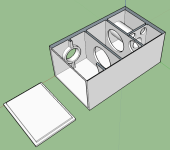
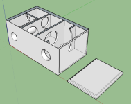
At this time none of the submissions take advantage of boost the output of both sides of the cone (e.g. 6th order bandpass), they are all either reflex variants or 4th order bandpass as far as I can tell (one seems to be BP4 with horn loading on the output). So I designed and submitted a simple 6th order parallel bandpass and it may get shown! Here is the bulk of my submission:
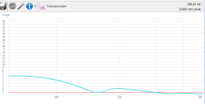
Response:
I also tried designing a large simple reflex, but it ended up being identical to the back half of the above BP6, with no advantages for these test parameters (size isn't penalized for example) so I didn't submit it. Conceptually I think it could be interesting to print a BP6 as a complete vented box with a separate front resonator, and test it both before and after attaching the front part.
I'm fully aware that the inaccuracies of winISD, the scale of this project, and my lack of 3D materials experience may make the entire design a joke; I'm very curious to see the impedance plot of the finished print if it gets used, to see if it correlates. I put some effort into determining the inside volumes of the chambers minus the port tubes before drawing up the enclosure, but the bracing is not really accounted for nor was any end correction made on the lengths of the ports (though the 'middle of the wall' ends should match reasonably with the winISD 0.732 default). Being a 3d print there's no excuse for the ports to not be flared, all edges rounded over, the bracing much fancier, etc, but I'm at the limits of my sketchup skills as it is...
Questions, thoughts? Anyone else want to try? Feel free to post it here if you do!
Here are the test and woofer parameters: https://docs.google.com/document/d/13YayzCsIZ58GIl6czQCEoz9ShTWKgAfU_1n6SGTBByo/
Intro video:
Video for how to submit:
Episode 1:
Episode 2:
Episode 3:
Episode 4: https://www.youtube.com/watch?v=y7KKPThsA8U
Episode 5: https://www.youtube.com/watch?v=KSvCiuMgGIo
Episode 6: https://www.youtube.com/watch?v=_ws6HA5aXzk
Testing is done at 4 frequencies (power or excursion limited, determined separately for each tone), 150hz, 198hz, 270hz, and 360hz (corresponding to scaled frequencies of 25hz, 33hz, 45hz, and 60hz).
At this time none of the submissions
I've designed a a large 6th order parallel bandpass box using winISD and Sketchup. I am using Sketchup Make 2017, which I had assumed was 'v17', but didn't see any way to export to STL. DAE and SKP are attached. Happy to save to older versions of Sketchup if needed, or download an older version that can export STL.
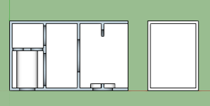
It's designed to be as loud as possible while minimizing excursion across the test bandwidth as much as possible. The back chamber is about 2/3 of a liter tuned to ~155hz, the front chamber is about a half liter tuned to ~360hz. It should perform very much like a vented box made of just the back part for the lowest two notes; no excursion problems at 150hz, possible excursion problems at 198hz (exactly the same as my best effort basic vented box design, fwiw). Then it should start getting some boost at 270hz from the front resonator, then get a massive boost at 360hz. Attached winISD graphs are shown at 10 watts.
Outside dimensions are 182mm x 108mm x 78mm, with 4mm walls. By definition it has to be a two part box; one end is the access panel panel which should slide in nice and tight. Its double thick since it isn't easily braced; half of it is designed to slide inside the main box. I don't know how to seal it such that it will still be removable! I also don't know how hard it will be to secure the woofer in place inside the box, and I didn't put in any reinforced points for mounting screws. The magnet is designed to go into the rear chamber (away from you when installing), though the tolerances are probably not tight enough to matter.
I've never worked with a 3d printer before so I don't know if my design is even printable. Everything should be supported from below except the rear chamber port tube, which runs parallel to the bottom without anything under it. Please let me know if I need to redraw that!
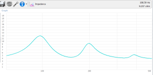
Response:
Hey Chompy! Ahh this looks brilliant! I look forward to doing this one! Ill have a play around with it if needbe in sketchup to get it to print well, i think it looks okay as is but ill have a closer look nearer the time of printing 🙂 Thanks for the submission!
Sam
I also tried designing a large simple reflex, but it ended up being identical to the back half of the above BP6, with no advantages for these test parameters (size isn't penalized for example) so I didn't submit it. Conceptually I think it could be interesting to print a BP6 as a complete vented box with a separate front resonator, and test it both before and after attaching the front part.
I'm fully aware that the inaccuracies of winISD, the scale of this project, and my lack of 3D materials experience may make the entire design a joke; I'm very curious to see the impedance plot of the finished print if it gets used, to see if it correlates. I put some effort into determining the inside volumes of the chambers minus the port tubes before drawing up the enclosure, but the bracing is not really accounted for nor was any end correction made on the lengths of the ports (though the 'middle of the wall' ends should match reasonably with the winISD 0.732 default). Being a 3d print there's no excuse for the ports to not be flared, all edges rounded over, the bracing much fancier, etc, but I'm at the limits of my sketchup skills as it is...
Questions, thoughts? Anyone else want to try? Feel free to post it here if you do!
Here are the test and woofer parameters: https://docs.google.com/document/d/13YayzCsIZ58GIl6czQCEoz9ShTWKgAfU_1n6SGTBByo/
Intro video:
Video for how to submit:
Episode 1:
Episode 5: https://www.youtube.com/watch?v=KSvCiuMgGIo
Episode 6: https://www.youtube.com/watch?v=_ws6HA5aXzk
Attachments
Last edited:
Or just pitch shift in real time. Instead of playing 6x low speed.
Is it limited to 2" drivers? or limited to just a box that fits in a model car?
if so a 5" or 4" speaker more feasible of doing something.
2 drivers push pull isobaric will half the size of box.
Small box still fits in car, larger speaker makes actual bass.
Then use typical 4th or 6th order bandpass high tuned for max output
At this time none of the submissions take advantage of both sides of the cone (e.g. tapped horn or 6th order bandpass), they are all either reflex variants or 4th order bandpass as far as I can tell (one seems to be BP4 with horn loading on the output)
That makes no sense given that both reflex and bandpass take advantage of both sides of the cone.
dave
The sealed section of a BP4 is not getting boosted like the ported section.
BP6P and BP6S, both the front and rear sections of the enclosure are getting boosted.
I've been following the competition and surprised he hasn't tested a BP6 yet.
BP6P and BP6S, both the front and rear sections of the enclosure are getting boosted.
I've been following the competition and surprised he hasn't tested a BP6 yet.
Dave that's true. What I said was incorrect and has been clarified. I meant to write something about both sides being boosted via a resonator, whether quarterwave or hemholtz.That makes no sense given that both reflex and bandpass take advantage of both sides of the cone.
dave
My thoughts exactly! Given plenty of space and a limited test bandwith, it seems like there's few downsides.The sealed section of a BP4 is not getting boosted like the ported section.
BP6P and BP6S, both the front and rear sections of the enclosure are getting boosted.
I've been following the competition and surprised he hasn't tested a BP6 yet.
I'm not sure what you mean? The videos are played at low speed to compensate for the speedup inherent to the experiment, and mostly done for our entertainment. These aren't trying to be useful real-world speakers, fwiw. Check out the videos for details.Or just pitch shift in real time. Instead of playing 6x low speed.
Last edited:
Everything is scaled-down to 1/6 of the actual build.
A 2" driver is 1/6 of a 12" driver.
25hz is 1/6 of 150hz.
33hz is 1/6 of 198hz.
45hz is 1/6 of 270hz.
60hz is 1/6 of 360hz.
A 2" driver is 1/6 of a 12" driver.
25hz is 1/6 of 150hz.
33hz is 1/6 of 198hz.
45hz is 1/6 of 270hz.
60hz is 1/6 of 360hz.
A 2" driver is 1/6 of a 12" driver.
Except that is not the relevant dimension the cone area? 2” & 12” are nominal numbers, and typically represent the bezel size.
The trick may work with film frame rates, but here i am quite leary.
dave
It won't be.
The Sd of a driver is based on the square of the diameter of its effective radiating area.
For a 12" driver, Sd is typically around 500 cm^2
One sixth of that is 83 cm^2. That's approximately the Sd of a 5.25" driver.
The Sd of a driver is based on the square of the diameter of its effective radiating area.
For a 12" driver, Sd is typically around 500 cm^2
One sixth of that is 83 cm^2. That's approximately the Sd of a 5.25" driver.
Closer to 2.5” CHN-40 Sd = 0.0023m2
The first 12” i popped up (Sonido SWR250) Sd = 0.0350m2
0.0023/0.0350=0.065714, ie the 12; has an Sd approx 15 times larger, making the logic of this approach fall apart.
dave
The first 12” i popped up (Sonido SWR250) Sd = 0.0350m2
0.0023/0.0350=0.065714, ie the 12; has an Sd approx 15 times larger, making the logic of this approach fall apart.
dave
It's still cool to see him test multiple enclosures with the exact same speaker.
Are you hating on your preference of enclosure type is not winning?
Are you hating on your preference of enclosure type is not winning?
I've really gotten into a big discussion about it, no.Have you stated that info to barevids?
I think it's the simple t/s parameters that really count, i.e. Vas, Qts, Fs.
If scaling down to 1/6th, then I think for design purposes, the following should apply:
Vas' = Vas/6
Qts' = Qts
Fs = Fs/6
So, once the Vas of the driver is 1/6th the Vas of a 12" driver with the same Qts, then the scaling should work the best.
Unfortunately the Qts of the test driver is pretty high, 0.8. Don't see many 12" drivers with that high a Qts, unless it's designed for IB/OB use, or there's an issue with it's motor, or it's a very cheap driver 🙂.
I think that's a 10" driver. If it was a 12" driver with an Sd of 350 cm^3, the surround would have to be huuuuge 🙂Closer to 2.5” CHN-40 Sd = 0.0023m2
The first 12” i popped up (Sonido SWR250) Sd = 0.0350m2
0.0023/0.0350=0.065714, ie the 12; has an Sd approx 15 times larger, making the logic of this approach fall apart.
dave
You are right, a 12” driver would be a 300.
I think that in post 15 F[subb]s[/sub] should be 6 times (ie higher not lower. Asking a 2” to have one a sixth of a 12: is going to be an impossible task.
dave
I think that in post 15 F[subb]s[/sub] should be 6 times (ie higher not lower. Asking a 2” to have one a sixth of a 12: is going to be an impossible task.
dave
FWIW, historically a 12" Sd = 78"^2/~503 cm^2, 8" Sd = 28"^2/180.6 cm^2, 15" Sd = 133"^2/858 cm^2 and if there were other sizes listed they aren't in any of my vintage DIY books, pamphlets, though assuming the mean of the 8", 12"is close enough, then a 10" Sd = sqrt(28*78) = 46.733"^2/301.5 cm^2, eff. dia. = sqrt(46.733*4/pi) = 7.714"/19.59 cm
Correct, Fs' should be Fs*16You are right, a 12” driver would be a 300.
I think that in post 15 F[subb]s[/sub] should be 6 times (ie higher not lower. Asking a 2” to have one a sixth of a 12" is going to be an impossible task.
dave
Last edited by a moderator:
- Home
- Loudspeakers
- Subwoofers
- Boom or Bust - scaled down subwoofer design series submission
