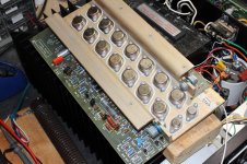
I'm working on restoring a Bose 1801. I've replaced electrolytic caps, opamp, carbon comp resistors, main caps, and added DC protection.
I'm having a stability issue in one channel. This is shown in the pictures. It starts happening at very low power. I was talking to Leestereo and he suggested playing with the value of the phase capacitor C8. It is 200pf originally. Raising it made things way worse but lowering it to 100pf solved the issue but destroyed the square wave performance. I don't have any values between 100 and 200 on hand. I tried a new 200pf cap and it had the same issue as the original.
I've had this issue 2 other times and one time I had to raise the value of the VAS cap. The other time it was the resistor in the output network, I don't know what it is called. R47 does that job in this amp.
I've attached the schematic.
Attachments
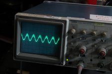
That looks like crossover distortion. Have you checked the no load and no signal quiescent current.
What did you replace U1 with. Is the compensation capacitor, C5, the correct value for the chip.
What did you replace U1 with. Is the compensation capacitor, C5, the correct value for the chip.
That looks like crossover distortion. Have you checked the no load and no signal quiescent current.
What did you replace U1 with. Is the compensation capacitor, C5, the correct value for the chip.
There is a touch of crossover distortion at higher frequencies so I might have to bias it a bit higher. What is happening to the top of the wave is oscillation though, right?
I used an OPA604. I used the same ones last time I restored one of these, they were suggested by an audiokarma member who has worked on a few of these. Haven't touched C5 but I haven't had this issue before.
The OPA is not my choice, far too fast!
This amplifier was designed around the uA709G and later the uA741 (without null adjustment).
I think it needs slowing down as 40MHZ is a bit too fast compared with a bandwidth of 40kHZ.
Probably get rid of the fizz by increasing the quiescent current very slightly.
This amplifier was designed around the uA709G and later the uA741 (without null adjustment).
I think it needs slowing down as 40MHZ is a bit too fast compared with a bandwidth of 40kHZ.
Probably get rid of the fizz by increasing the quiescent current very slightly.
The OPA is not my choice, far too fast!
This amplifier was designed around the uA709G and later the uA741 (without null adjustment).
I think it needs slowing down as 40MHZ is a bit too fast compared with a bandwidth of 40kHZ.
Probably get rid of the fizz by increasing the quiescent current very slightly.
What are the consequeces of the opamp being too fast?
Squarewave performance looks good on the other channel. No ringing. Same look on the problematic channel but with the issue of course.
Last edited:
What are the consequeces of the opamp being too fast?...
Instability. Oscillation.
In AB power amps, often first seen as signal comes out of an under-biased condition. Is bias set properly?
Many of these old amps with slow output transistors in quasi, driven by fast ones, with a lot of loop gain were intended to be biased fully class B. That is, no bias in the outputs and quite a bit in the drivers. When biased into very light AB they oscillate, and can’t be fixed regardless of the compensation. Original Phase Linears, for example. Stable at no bias which is the factory setting, unstable (and more crossover distortion, not less) at typical bias used in PA amp use, stable again at high bias which is too much for the heat sinks. Output stage is similar, overall topology looks like an attempted improvement. I would expect the same issues setting the bias. At least this amp has enough heat sink to up the bias into the stable range.
Many of these old amps with slow output transistors in quasi, driven by fast ones, with a lot of loop gain were intended to be biased fully class B. That is, no bias in the outputs and quite a bit in the drivers. When biased into very light AB they oscillate, and can’t be fixed regardless of the compensation. Original Phase Linears, for example. Stable at no bias which is the factory setting, unstable (and more crossover distortion, not less) at typical bias used in PA amp use, stable again at high bias which is too much for the heat sinks. Output stage is similar, overall topology looks like an attempted improvement. I would expect the same issues setting the bias. At least this amp has enough heat sink to up the bias into the stable range.
The last one of these I did got all new onsemi outputs. Could that have made a positive difference?
I tried a TL071 opamp and the issue started at about 0.37VAC across the test loads instead of 0.27VAC.
I have a couple of the original op amps.I had an 1801 and changed them out for some faster LME types(can't remember the number),thinking newer is better. There were loud pops on power up and down but other than that I couldn't tell the difference.I traded a guy in Ottawa for a McIntosh a few years ago.If you are interested I can send them to you for the cost of postage.PM me your email if interested and we can go from there.
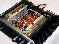
So I finally got this working. It was what I kind of feared but wasn't too big a deal in the end. It was a problem with output transistors that passed diode check.
I got a Cricket tester and tested all the outputs. The ones that were in the problem channel as well as the rest of my spares. There are two junctions that are supposed to show gain. One is supposed to deflect the needle about 2/3-3/4 and the other has just a bit of gain. The latter had no gain on all the parts I pulled out of that channel. Not sure if that was actually the problem but I'd moved the outputs from the good channel to the bad one and done a successful power test and it passed. So I knew 100% the issue was hidden in this pile of outputs. I put a set together from my spares that measured decent with measurable gain in the second junction. Then I did a proper bench test to full power and it passed.
I'd tried the outputs oreo offered me in the post before this one and it made it slightly farther without clipping but that was still under a watt. I have the 604 op-amps in it now.
It looks decent with a 10kHz squarewave too. A tad slower than amps from later in the 70s.
how did you add dc protection? can you please give me more details? any photos? how is it wired to the amp?
how did you add dc protection? can you please give me more details? any photos? how is it wired to the amp?
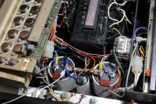
I installed this kit in my 1800 / 1801 amplifiers http://analogmetric.com/goods.php?id=1935&from=rss
There are many other offers for this kind of kit, juste google it. The Nec UPC1237 is a very nice chip found in many commercial products. Datasheet here https://www.allaboutcircuits.com/electronic-components/datasheet/UPC1237--NEC/
Speaker connection delay can be set by changing a capacitor value, factory default delay is perfect though.
Wiring is straight forward : as with any other similar kit, there's an input wire coming from the amplifier board and an output going to the speaker positive binding post. Ground is common to both channels.
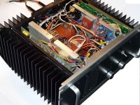
For the above kit, you'll need an additional AC transformer. As you can see I installed one (brown cube on one of the photos).
Attachments
I have a circuit I designed myself, using a big omron relay. But I need to tear it apart again because the small transformer I installed to power it started buzzing loudly.how did you add dc protection? can you please give me more details? any photos? how is it wired to the amp?
- Home
- Amplifiers
- Solid State
- Stabilizing Bose 1801