Fender Hot Rod Deville 410 Clean Up
My son bought a used Fender Hot Rod Deville 410 original and we are going to go over it since he says it doesn't sound right. Googled it and many say that it it is similar to a Blues Deville but that one unused half of a 12AX7 was added for even more distortion in the drive channel and they went too far on gain. Some suggest replacing the tubes with 12AT7s but he tried that and one in the second stage seemed alright but that it still was not right.
Another person suggests changing the second pre amp tube to a 12dw7/7247 which puts a 12AX7 half in the clean channel and the 12AU7 half in the distortion channel where the lower gain fits well. We will try this.
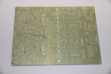
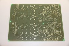
I opened it and noticed a date of 1996 on the circuit board, not sure if that is the date that it was designed or the actual age of the unit which would place it just shy of 20 years old.
First impressions are that the jacks feel very cheap, and I don't like the circuit board from a reliability perspective but I suppose it works.
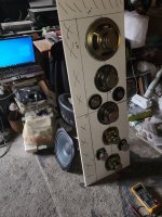
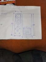
Speakers are four 10" Eminence for Fender. He wants two 12" but I don't think I'm up for making a new baffle board we'll see.
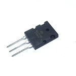
The red printing on the output tubes is burnt to brown in some areas and I have a feeling that it was red plating.
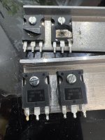
All the main signal paths are tubes 12AX7 preamp and 6L6GC outputs, but the reverb, pre out and power amp in all employ TL072 OP amps. Fender seems to like these as they are in many of their newer amps. I believe that these snap rail to rail when over driven, IIRC, anyone know for sure? Let's hope that they are never over driven.
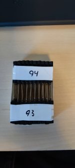
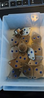
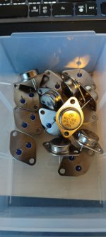
Pulled the tubes and they are all Groove Tubes, 12AX7s say Sovtek on them not sure about the 6L6 GC but my friend noticed that they had welded plates - nice! One pre amp tube tested weak and the outputs tested fine - still I believe that they need to be tested at full power since the tester doesn't stress them as in circuit.
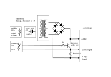
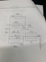
======== Schematic Walk Through
Schematic from Fender is here in .pdf:
http://support.fender.com/schematics/guitar_amplifiers/Hot_Rod_DeVille_schematic.pdf
Output plate supply is 485V! I'd prefer something closer to 440V.
Even the preamp supply seems high at 388V.
The input stage looks like typical Fender with the 1 and 2 jacks but they've combined the typical
two channels into one with relay switches to raise the gain for the dirty channel.
V1A has the typical plate and cathode resistors with a large cathode bypass cap of 47 uF providing
increased gain over the full frequency response. This is larger than needed but they probably are
going to roll- off the low end with the interstage coupling caps so that is fine. Looking closer all
four preamp stages have the typical 1.5K cathode and 100K plate resistors, smaller cathode bypass
caps are used to provide response shaping. The response effect can be calculated here:
Cathode Bypass Capacitor Calculator
There are two front end pots, gain for the clean and drive for the distortion channel allowing the player
to preselect two different volumes depending on which channel is selected from the foot switch.
It is interesting that the low frequency roll-off is quite different between the two channels and also
the much lower value than typical, grid leak resistor makes the roll-off frequency dependent on the
pot settings. Here are the values for low volume settings:
Clean: .022uF into 470K for 15.4 Hz
Dist: .0015 uF into 430K for 246.8 Hz
Minus 3 dB can be calculated here:
High Pass Filter Calculator
This blocks LF from the distortion channel since bass does not sound good when distorted but I have
to wonder if they went too far.
R44 could be increased to make the LF cut less dependent on volume position, perhaps it was deliberate
to keep it clean at higher volumes? To keep the cheap speakers clean, just speculation?
The Bright switch puts in the second stage cathode bypass cap but it is disabled when the distortion
channel is selected. The cap is a small value so that it only boosts the high end.
Output of the second stage feeds the tone stack which looks like the usual Fender arrangement.
The relay switch that disables the Bright control also further cuts the high end by enabling C3 as a
shunt at the input of the 3rd stage. Presumably to cut the highs that might get too harsh with more
distortion.
This amp has the amusing, "More Drive", option where a 1 uF cathode bypass is enabled on stage 3 by
Q1 and a 22 uF cap on stage four through Q2 - JFET switches. There are actually two foot switches, one
to select clean or distorted channels and the other to enable "More Drive".
The fourth preamp stage is only used for the distortion channel and it is removed and muted by the
second relay. A Master Volume pot is provided at the output of this fourth stage and therefore does
nothing when the clean channel is selected. This allows the distortion channel to be driven very hard
without being forced to drive the power amp to full output. Turn up the drive to get as much distortion
as is needed then turn down the Master for a comfortable playing level. Interesting to note that the AC
signal voltage shown at the plate of the fourth stage is 17.1 V. This is probably enough to blow out the
inputs of the TL072 OP amps since they only run on 16V supplies, so back to back Zeners clamp the
signal at +/- 15V, I might have chosen 10V to keep the levels more reasonable.
The output of the final output relay is attenuated to feed a TL072 buffer U1A for the Preamp output
jack, this is not in the path to the power amp.
Interesting that the relay output is not attenuated to feed the TL072 driving the reverb spring, is it
normal to distort the reverb driver in a Fender amp? If not I'd probably attenuate that drive signal
by 6 to 12 dB. I'd also use a more robust driver, something like a headphone driver for the reverb
drive OP amp. I'll have to check the gain of that stage perhaps it is unity gain, not sure since I don't
know the impedance of the reverb tank.
OP amp U2B amplifies the output from the reverb tank to the Reverb pot the output of which is
mixed into the power amp input. Some response shaping is used.
OP amp U1B is an input buffer with gain for external sources feeding the power amp.
The power amp is very close to a standard Black Face, no ultra linear connection, but with a few
very small 47 pF caps added probably to tame the massive harmonics from the distortion, and
a few diodes added probably to protect the tubes and output transformer from arcing if the amp is
ever operated without a speaker load.

![20230604_040409[6538].jpg](/community/data/attachments/1088/1088206-1a50f6a3e1570b142485021ede7472c3.jpg?hash=GlD2o-FXCx)


 !
!