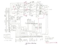
I am using a 10W TPA3138D2 amplifier for my projects, and I would like to be able to use it with headphones as well. However, the output signal for the headphones is too powerful and I would like to find a way to switch the output between the speaker and headphones with two different power levels.
Currently, my system is wired so that when the headphone jack is inserted, the speaker is disconnected. View attachment 1258355
The signal starts from A+ (amplifier output) and goes to SP+ (speaker cable).
How could I modify the circuit so that I can change the gain and disconnect the speaker when the headphone jack is inserted?
The circuit includes a classic preamplifier based on TL072 that can be modified. Any ideas or suggestions are very welcome, perhaps there is a type of jack input with a different pin configuration, or one that has an isolated switch in parallel, or...
Hello everyone.
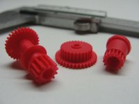
I'm simply curious. I have a Technics RS TR373 deck that hasn't been used for a few years because some gears have broken.
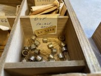
I bought them on eBay from someone who makes them in Poland. (there are really few who make replacements).
They are nominated as RXL0106; REM0043 and RDG0206.
My question is, does anyone know why Technics/Panasonic made them from a totally different material than the rest of the gears on the deck and why they crack and break over time?
That detail catches my attention. Could it be to reduce noise?
Another reason?.
The ones I bought are made of polyurethane resin, I think they are stronger than the originals, but harder.
Greetings.
Visaton offers a design software, just that it only has a Windows version and I can't use it. If anyone can recommend me a total closed volume for the driver (as I understand, a closed box would be a good bet for this driver) and the updates needed to the original or the adaptation crossover, I think I can manage from there.
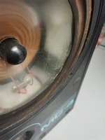
I've recently inherited my late brother's old Hi-fi, which needs attention, but one step at a time.
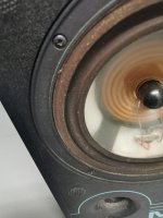
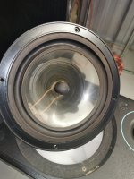
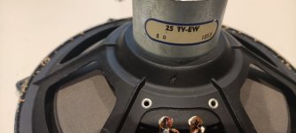
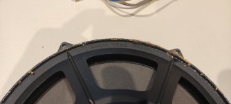
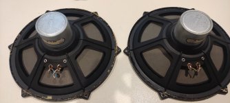
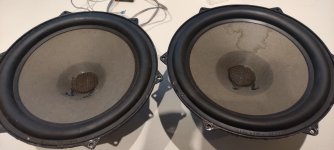
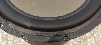
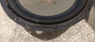
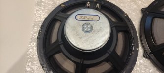
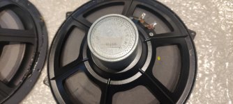
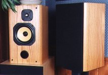
First the problem is with the speakers. I've been trying to find info on Musical Fidelity MC4 Drive unit specs.
These were made in 1987 (Stamp inside the enclosure). He then had a Musical Fidelity A100 which didn't have any output protection and subsequently blew one channel and took one of the bass drivers along with it. He had it repaired but it was different from the other speaker. Not much different, but one of them used a black diaphragm/spider and the other is yellow.
I'm not too sure which was damaged as this was a long time ago. I'm presuming the newer one is the Black one.
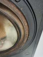
Anyway, he hadn't been using his setup for some years, and with the smokey environment, the nicotine had attacked the rubber surround, and the cone on one of the drivers, and had started to crumble.
I cannot find any info on these. I have tried reaching out to Martin Collums of Hi-fi Critic, but nobody responded.
I have tried Musical Fidelity, someone did contact me, but they were at a loss, as Musical Fidelity had been taken over by someone else since then.
I've tried Wilmslow Audio, but they would only repair the surround and couldn't provide me with any details as to what these drivers were and what I could use as an alternative.
Does anyone have any info on the drivers or as to what I could use?
I'll be wanting to replace the Tweeters at some point too and upgrade the crossover components.
Google hasn't been much help at all.
I would like to get these big babies to sing again.
The W4-2142 is a full range, the 123A plays much higher than usual 12” and the D2905/970000 can be crossed < 2k therefore the big question is where to put the crossover points and how steep ? Is the W4-2142 too small for the 123A ?
Question #3:
If I cross the tweeter low, I would add a waveguide WG-148R from Visaton and mount it close to the W4-2142, but what if I cross the tweeter high ? Should I mount the tweeter firing to the top, creating ambience with ceiling reflections or should I mount it the traditional way ?
I'm trying to restore a Yamaha M-4 Power Amp bought one on eBay what a nightmare I am in need of some Transistors if anyone can spare any they are as follows.
I just replaced the front panel board on my 1st generation SHD, the OLED display pixel fade had gotten really bad. miniDSP sold me a replacement module out of warranty.
Here are some pics of the actual OLED part in case anyone wants to hunt for a second source.
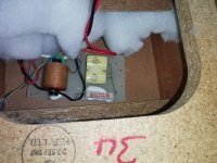
hello from France, I recently got an ml 27.5 and need advice for its overhaul, there is a slight hiss in the speakers and a bit more to the left. I replaced the 9 Rifa, the 6 chemical condos on the 2 rear panel cards. and the 2 small Spragues accessible on the power cards. The breath is always present. there are still the 2 other small Spragues which are very difficult to access to replace. what do you think of what I can do?
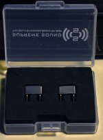
I bought a buffer kit based on Muscial Fidelity's X10 design.
I used a pair of 6N1ps (all I had) but otherwise built it as drawn below.
There was no onboard power supply but the seller recommended +-28v so I used a 24-0-0-24 transformer to give a raw +-50v (the Vigotronix pcb transformer has only 25% regulation) This seems a strange way to power a tube circuit to me and it could be redrawn and reconnected as a +80v supply.
Th heaters initially were powered from a 12v switch mode psu. They are wired in series and are floating so I tied one side to 0v with a 1k resistor. (switching noise was evident so will replace it with a LM338 based regulator.)
U1a's anode current was a lowly 0.13ma and the other triiode's was 1.5ma.
It measured well using REW - well below 0.1% at ~1v RMS into 4k7 and the gain was slightly greater than unity (by10%) Square waves at 1 & 10kHz were clean.
Comments are welcome, especially in respect of tubes and anode currents.
The Chinese seller's claims were, as always, exaggerated, although the 6N1p might not be a good choice.
Hi gang... this should be easy, but got stuck. How do I test my horns at 1M when my horns are 36 in" long?
That puts mic at 3.37" from mouth. Seems weird. Even 4' seems awfully close.
Zene
I've been lurking here for some time but never really participated in actually building something - hence the lurk. Now though... approaching retirement (although do you ever retire when you run your own business?) I've decided to create a dedicated workshop space where I can fiddle with speakers and electronic gear. This is something that I did way back as a teenager when my insane parents let a 12 year old muck around with s/h valve radios - one of the first things I learnt was that 1,000 DC hurts rather more than 240v AC. I made it to 13 and built loads of stuff - largely picked up from an old British mag called 'Everyday Electronics'. I guess if you remember that then you're probably, like me, a boomer.
First off I've got a load of gear to renovate/repair: Rogers Cadet III amp, Leak Stereo 20 amp, a something Marantz, then a pair of Leak 15 ohm Sandwiches, Wharfedale Laser 80s, Celestion Ditton 25 and 15s, TDL RTL2s and 2 KEF B139 and T15s... thinking of a transmission line - something that has always fascinated me 🙂 Then I'm wanting to try some of @Scottmoose designs and a Frugelhorn. That ought to keep me going until the hand-eye coordination buggers off south!
The RTL2s are first for treatment I think.. I gather @mikesnowdon did much on these it he's still around - he made some very useful posts.
So the LRS plus is finally back in stock and i ordered a pair for our weekend getaway place where placement away from the walls won't interfere with everyday life (not an option in our main home) From what i can tell from posted 3rd party measurements and shared experiences, these roll off pretty quick below 100hz and have no real midbass impact to speak of......that simply won't cut it for me when i wanna listen to Bill Ward or Bonham.
So the whole SLOB thing has me intrigued......and i'm wondering if a 15" downfiring woofer under the panel built into a stand like thingy would work?.....what to do with the rear wave?......box on all four sides and open back only? (woofer is qts .77 and FS 31hz with 550w available and active DSP)
Some other folks have used Vandersteen subs to much success which use three 8" woofers in a sealed box.....front and two side firing......maybe that's a better approach for midbass?
And then there's always a true cardioid approach.....say two 10" woofer/subs per side lined up front to back and active DSP?
I put the ground into the power in on the amp first, then when I put in the power, I heard a shock. The fuse was blown at the positive battery terminal.
Do you think my amp is okay? I can’t test it yet until I get a new fuse for the fuse holder at the car’s battery.
I’d like to know so I can order a new amp ASAP if needed
I've made a phono preamp based on Le Pacific, for MM duty.
Sounds great for such a simple thing.
But, I noticed it doesn't handle well very high voltage output cartridges, such my Shure M44-7.
It gets a bit overloaded and soundwave is clipped, especially the bottom part.
Here is the schematic by the way:
Would it be helpful to increase power voltage to 24 VDC?
The KIT includes all of the necessary parts to build a Raspberry Pi Player / Streamer with built-in linear power supply. You will need some basic soldering skills and it takes at least 2 hours to assemble the parts. Overseas customers need to pay an extra 7% for PayPal service charge. Shipping cost will be incurred depending on destinations.
The new model STEALTH V2 includes Analag Devices ADUM3160 as the USB Galvanic Isolation, which eliminates the noise introduced by the touchscreen。STEALTH V2 can also works as a Roon endpoint,For details please refer to the Youtube demo。
Usage of the KIT
-Digital transport / streamer / music server, supports Spotify, Tidal and Qobuz
-Media server with an internally mounted 2.5" SSD (not included)
-Digital to Analogue Converter with I2S DAC HAT
-CD player / ripper with an external USB CD drive
-Supports audiophile OS including Volumio, DietPi & Debian
Case:
-Aluminum alloy fabricated with mixed CNC and LASER cut
-All black anodized matte finishing
-7.9" HDMI 400x1280 touch screen
-Opening at the bottom, can change OS with ease
-Dimensions: 240(W) x 220(D) x 100(H)
-Support standard D-type sockets
-RCA jacks included
-Native support for Allo Boss 2 DAC HAT
Power:
-40VA audio grade R-type transformer, 5A output
-Built-in high precision, low dropout, large current LPS
-TL431 as a voltage reference
-9x Nichicon FW Series capacitors
-Ultra low ESR,CLC filtering topology,WIMA MKP10 for final decoupling
********************************************
Note:
Supports Raspberry Pi 4B ONLY
Touch screen is included
No Raspberry Pi or DAC included
********************************************
I have James Audio transformers for SET amps. They will look and sound great on any DIY project. I bought them in 2014 to build 300b amp but I never had a time to finish the amp. They are in absolute top condition, didn't even peel the clear stickers from the logos. That being said, I am only interested selling them as a set, not individually. I rather have someone local to LA/SOCAL area to buy them because their total weight is around 40 lbs and I don't want to deal securely shipping them. I am looking for $1000 for all of them.
There is currently one person considering buying them but please free to drop comment if you are interested. I will be in touch!
Here is the Picture of them:
Here is the list:
Power Transformer JS-9612-2: It is huge and super heavy.
Output Transformer JS-6123HS
Current: 90mA, 20W
Primary impedance: 2.5K / 3.5K / 5K
Secondary impedance: 4-8-16 Ohm
Frequency Response: 15Hz ~ 68KHz - 3dB
Material: Orientcore HiB
Dimensions: 90 x 80 x 110 mm
Weight: 3.2 Kg (7.0 lbs)
Hello, I'm new to the Forum so if I'm asking a question that is already been covered, please excuse me.
So, I've been trying to connect my Yamaha receivers sub out to my ao7 Pro to power my subwoofer so that I can take advantage of the Yamahas crossover, and I cannot get it to work. Does anyone know if the ao7 pro is capable of receiving the sub out signal from the Yamaha through its RCA input?
The first of the "premium cable" manufacturer, remaining anonymous because them liken to suing everyone in sight...started about 1979, just about the same time as IQ rates started falling. Now, the powers that be insisted the IQ testing was fatally flawed, but that did not affect the results even using the "updated" versions of IQ testing. So, we went from simple speaker wiring to interconnects, thru "magic boxes" up & thru "magic pebbles" & all their wild claims. Very early on, straightforward double-blind tests ensued, discovering, "You can't hear an expensive speaker from a cheap one, you can't hear an expensive "super-speaker cable" from a cheap stretch of zip-cord, you can't hear the difference from a cheap $30 DAC from a $3500 DAC..."
From every corner we hear attempts to discredit double-blind tests, just like those trying to discredit the IQ testing ...& no, even concert violinists don't covet Stradivarius violins because they can't hear any differences. Even a collection of so-called wine-connoisseurs can't even decipher a red wine from a white wine. Double-blind testing strips away all pretensions large & small.
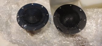
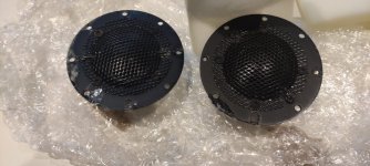
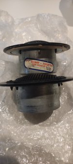
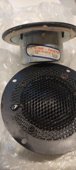
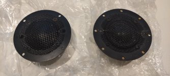
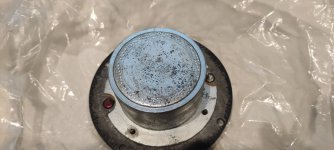
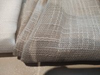
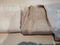
Does anyone know an online source for metal mesh sheets that can be used for speaker grilles? I’m looking for something with large pores, like the attached pic. So far, I’ve only found small pieces, or wholesalers with minimum $1,000 orders, and I only need a few square feet of it.
Has anyone used that loose cellulose insulation that they blow into the attic for stuffing speakers? Does it work well? Should one put it in a mesh bag or something to keep it from getting in the driver innards?
Hi all! Recently took the plunge down the DIY rabbit hole, putting the fun and passion back in my music listening! I recently purchased a tube amp kit, vendor shall remain anonymous for the moment, and am not able to get output. This particular kit has multiple test points on the PCB and there are a few that do not measure correctly. What is curious to me is with all these test points the kit vendor is unable to assist me other than to say it is either a bad solder joint or misplaced part. Wouldn't the point of having multiple test points to be to help isolate the problem?
Basically, it is about a nice EQ trick that allows some LF boost and "subsonic" filter for bass reflex boxes - allowing various design choices. I am especially interested in making an undersized BR box, since that is the only other option besides a sealed box for my smaller listening room.
I tried to make some simulations in Hornresp and using this kind of EQ seems to do what I need for the SPL levels I need. I especially like the excursion control without using a real high order subbas filter.
The article mentions using a shelf filter in MiniDSP (I actually happen to have one), but AFAIK, there is no shelving filter in Hornresp. So I used two peaking filters, one to boost and one to cut plus a first order highpass to approximate the high Q shelf filter. Is that equivalent, or is the shelf filter better in some regard?
I would like to first see in Hornresp what is possible before I start cutting wood, the final filter would be of course based on measurements. Am I on the right track?
The intention is to build a relatively small two way system with a large 400 Hz cutoff horn, the XO will be somewhere around 600 - 900 Hz, which would be good for 12" or maybe even 15" woofer, but there is not much space available for a large box.
Hi all! Just a silly little thing really - I've just put together an IcePower 125asx2 class D amp kit from EU company Sound Imports, it all went well, despite my limited experience and zero instructions! Just one thing, the power LED (GP150 Power-Button-Kit from Ghent it seems) is way too bright - could I tweak something to lower this brightness do you think? I can see the AUX out socket it is connected to says it is typical 24v according to the IcePower data sheet. Or maybe a better switch that could fit might have adjustable brightness or colours etc? I can of course just disconnect it, but was hoping there might be maybe something I could do electronically - I wouldn't have a clue but you proper DIY folk probably will! 😊
It was 2017 when I posted “Beyond the Epos es22…” and I still haven’t chosen my Troels G. speaker kit! It would be very good to get some fresh advice on my 2021 WAF* approved shortlist of 3 (*N.B. I have permission to build one kit only).
I listen to all genres except organ music and have no plan for subs. Insight into musical interplay/intent/nuance is much more important to me than HT, but obviously, reasonable quality bass is a prerequisite.
Room: 25m2 – two doorways, always open, one at the far end from the speakers and a wider one between them. Speaker placement in free space, up to 150cm from side walls and up to 85cm from front face of speakers to the wall behind them.
Origin Live Resolution Mk2/Encounter Mk3/ Dynavector 10x5
CDX/Pardoe XPS
Modded NAC72/ Avondale S101 80/90 watts, with NCC220 modules coming soon.
es22 speakers - reluctant attenuation of volume for some vocals, with CDX.
DTQWT single “l2” (level 2) 2,400 euro
Used by TG for 2 years in his 25m2 living space.
Owners report listening position relatively uncritical.
TG’ s suggestion of up to 40cm from rear of speaker to wall easily achieved.
Offers scale and quality lower frequencies.
High efficiency brings rewards, even with solid state?
Will it sound as transparent as best of the rest?
Money spent on high efficiency design components for DTQWT wasted, because less expensive/efficient designs, eg Ekta, can offer similar virtues, given 90 watts of good quality A/B SS?
Ekta Mk11 (Level 2) approx 1,600 ero
TG comments on wide and deep soundstage, comparable with ATS4, even at lower levels (an important aspect re my CDX player)
He claims 38hz @F3 … might this be good enough for most listening?
How much space needed between speaker and wall?
TG also claims that size matters, expense of ‘Illuminator’ units given limits of 7” woofer?
Faital 3W (Be level 2) 1,450 euros
Appears very good vfm, even with Beryllium tweeter
Size of woofer
Can rock
Drive units made in my country of residence!
Risk of overloading room with 10” woofer in bass reflex designs?
How much space required between speaker and wall? How critical is the listening position?
Mid range/sound stage able to compete with Ekta and DTQWT?
At limits of WAF - needs exquisite veneer job/and beautiful, black stands!
(Also considered 761 and the somewhat ungainly, but relatively inexpensive 861. Troels enthuses about good measurements, with this design… but zero feedback from any owners. I’m puzzled by the lightweight nature of these constructions, compared to e.g. the massively braced Ekta, Do these 2.5 Ways offer ‘balance’, or a Jack of all trades compromise to the mid range?)
If I use AC power cables for main connection like this about NBS OMEGA CABLE PRICING
I must use also absolutely high quality main power switches.
But this one are hard to find.
Here a little overview:
Of most models I don't know what is here to prefer and to avoid.
Thank you very much for your comments.
The decisive factor here will be the quality of contact material that need to process the voltage flash of inrush currents - especially by large main transformers - so I think.
The D202 is backordered at Parts Express at the moment, but they are supposed to be getting more in. I asked if they had any other info about expected future availability, but they said they have no information on inventory levels at JBL or how long those might last for either driver.
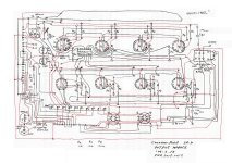
The other half of the Akai conversion I'm doing(now that I have the Ef86 pre mostly sorted(thanks) is based on a 12ax7
It also uses a shure M67 input transformer.
The problem I'm seeing is that it will overdrive itself before it overdrives the inputs of my UAD apollo 11
So whilst I can record a clean signal, it is not very loud. For a regular not too loud vocal this happens between 4-5 on VR1 At this point I am only halfway to distorting on my Apollo 11 unit. It would be nice if I could get a louder clean signal at the Apollo 11 unit, so I can meter there and not the U meter on the pre
If I turn up the pre louder it just starts distortion and I get a distorted flattened signal reminiscent of Skeletor
Coincidentally or not, this distortion happens when the VU meter of the preamp bounces into the red. However this VU meter is actually powered by the output transformer and power amp.
Originally the schematic had a connection at the preamp output which grounded the input of the power amp when a patch chord was plugged into the preamp out., however this also turns off the VU meter which frankly is no fun!, also i jumpered this on mine and it made no difference ot the distortion issue, except to turn off the fun VU meter.
Any ideas what's overdriving here? Is this another output impedance mismatch ?
I’m attempting to reverse engineer T/S parameters of the woofer of loudspeakers; Braun LS200. I know for accuracy and precision, it should be done by measurement. Nevertheless, I did the calculation because I’m just curious whether the formulas on the textbook would work.
Well, here are all of the parameters I found in the spec sheet and speaker reviews.
Woofer diameter = 10”
Cabinet type = sealed
Cabinet volume = 47 litres (per single woofer)
Cabinet resonance = 36 Hz
Cut-off frequency = 28 Hz
The target is to find Fs, Qts, and Vas of the driver.
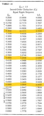
Step 1: Starting by finding Qtc from the relationship of F3/Fc = 28/36 = 0.78 or approximately 0.80, then looking at the table 1.12 in Dickason’s cookbook we obtain Qtc = 1.0.
Step 2: Assume the possible Qts are 0.3, 0.4, and 0.5. Looking at table 1.8, we obtain alphas of 10.11, 5.25, and 3, respectively.
Step 3: Verify usable Qts by the formula; Qts = Qtc/(sqrt(alpha + 1)), then, the usable Qts are only 0.3 and 0.5.
Step 4: From the relationship; Fc/Fs = Qtc/Qts, or Fs = Fc x (Qts/Qtc). We obtain Fs = 10.8 and 18 Hz. But, only 18 Hz should be valid because 10.8 Hz is too strangely low, IMHO.
Step 5: Therefore, the valid Qts should only be 0.5. And alpha should also only be 3.
Step 6: Vas is founded by Vas = alpha x cabinet volume, thus, Vas = 3 x 47 = 141 liters or about 5 cu.ft.
In conclusion, the results are as follows:
Given parameters:
F3 = 28 Hz
Fc = 36 Hz
Qtc = 1.0
Alpha = 3
Driver’s parameters:
Fs = 18 Hz
Qts = 0.5
Vas = 141 litres, or 5 cu.ft.
Basically, I’ve tried verifying by myself by putting these values in online calculators. And the results were given as predicted. However, I’m still unsure if I did it correctly. Anyone please verify my calculation.
I'm a big fan of the Gedlee works on distortion perception. I've been preaching that low order nonlinear distortion is much preferable (less audible) to high order nonlinear distortion for a long time. This shouldn't be a surprise to most of you. Especially SET fans such as myself. 😱
What should be a surprise though- is that nonlinear distortion (THD & IMD) is most audible at low listening levels!
Gedlee's work appears to claim that speakers sound worse at higher levels not from nonlinear distortions (obviously this would have it's limits), but from diffraction! Diffraction appears to be more audible as you increase SPL!
So most of us know it's optimal to: round over our baffle edges, not use squares, offset drivers, etc. but I'm going to investigate directivity's influence on baffle diffraction. Mathematically, there should be an optimal baffle size to driver size, as larger drivers will beam frequencies sooner than smaller drivers.
This is of large importance and also a substantial advantage to fullrange drivers! Diffraction mostly effects higher frequencies. A driver which will beam higher frequencies, which would be effected by baffle diffraction, will in theory mitigate effects of diffraction. Much work has been done on constant directivity designs- but it may be the diffractions effects are most audible with acoustically small radiators with a high frequency passband. Obviously these would have wide directivity; maximally influenced by baffle diffraction. Ironically this would be all normal dome and ring tweeters.
I would also like to point out that many people have preferred smaller baffles to larger baffles. Gedlee's work not only suggests that diffraction is more audible the more it causes linear distortion (peaks and dips in frequency response)- but audibility increases with time!
A larger baffle will require a frequency to travel longer before it is radiated as baffle diffraction; therefore increasing time until radiation. This may be a large reason many have preferred smaller baffles! (Other than WAF 😛)
For sale: 45.1584 MHz clock. The best, period. You can read about the rakings of clocks in IanCanada’s most recent thread, as may be seen in: https://www.diyaudio.com/community/...fight-the-jitter.192465/page-532#post-7520451 and in post 10,630. The 45.1584 MHz version will have even lower phase noise. $350 including shipping in the US.
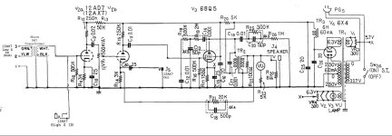
I have a counterpoint sa-2000 hybrid preamp/line control amp , it has 2 valves in it and I’m wondering which of these will have more of an effect on the sound ? Should I wish to tube roll
First of all, thank you for your interest!! It is mostly aimed at the European area but everything is possible.
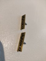
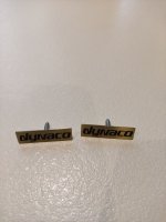
Offering a working speaker set for building a stereo set Dynaco A25. I ordered it from Holland unfortunately no time to realize it. According to the previous owner from Holland, it is functional. Because I don't have any connection options to test, I tested it with a battery. with correct polarity reversal, i.e. on and off the membranes hit outwards, reverse polarity inwards. Will be well packaged. See also my other ads. We are a smoke-free and pet-free household. Private sale, no guarantee, no warranty, no returns, errors excepted.
The dynaco logos are also included but only in the first set and the coverings in for two sets and 2 colors. I have 2 sets of speakers.
If you are interested please let me know. Greetings Alfred
First of all, thank you for your interest!! It is mostly aimed at the European area but everything is possible.
Offering a working speaker set for building a stereo set Dynaco A25. I ordered it from Holland unfortunately no time to realize it. According to the previous owner from Holland, it is functional. Because I don't have any connection options to test, I tested it with a battery. with correct polarity reversal, i.e. on and off the membranes hit outwards, reverse polarity inwards. Will be well packaged. See also my other ads. We are a smoke-free and pet-free household. Private sale, no guarantee, no warranty, no returns, errors excepted.
The dynaco logos are also included but only in the first set and the coverings in 2 colors. I have 2 sets of speakers.
Im looking at this amp on the bench thats really unstable. Under no load, it passes audio, but the audio is shaking on the scope. I guess the amp is oscillating. With a small load the amp will play for 4 seconds then pop, then play again. I cleaned and tested all the pre-amp controls but that didn't help things.
I dont see these style rockfords much and really have no place to begin. Any pointers?
Burson audio sent me a pair of these opamps to try out. Here are my listening impressions. First, gear used. I used the opamps in an Aiyima A04, a fairly popular small Class D amp. My speakers are Focal 133's, custom Zalytrons from the 90's with Focal drivers; 7” double voice coil kevlar woofers and 1” titanium tweeters in a vented 15 litre box. I've used them for over 20 years as critical reference for test mixes. Mistakes are obvious, but when everything's right they are a dream. My source is a PC playing digital mp3's at 320 kbps 48 kHz. I had previously replaced the stock opamps in the aiyima with OPA1656's.
The Burson opamps come in a tidy package, snugged into a thick slab of rubber which fits in a small custom plastic hinged box. They are encased in metal and were extremely easy to slip into the amp's sockets. Once the top was off, 30 seconds for the entire operation. As soon as I put on the first track I was gobsmacked by highs. Really bright and nowhere near the bottom I was used to. But incredible soundstage. So I let them run for a week before listening critically. After 60 or so hours they had smoothed out nicely. All the bass was back. But they still had somewhat edgy highs. I listen to mostly jazz, which can run the gamut. But acoustic stuff is my favorite. What knocked me out was the great ambience. Reflections in the room were clearly more obvious. After a couple of weeks listening to the broken in chips the overall sound still strikes me as too bright for my ears. The OPA1656's just sound wonderful and non fatiguing. The Burson chips seem to have more pizazz but I get a sensation of earache almost right away. I've always been sensitive to midrange and that may be part of it. Guitars usually seem over mixed to me. If you're into electronic music they may be just the ticket.
Which alternatives do i have with Fostex FE208EZ as a midbass? Horn on top and 18 inch sub.
Range ca 100 to 800 Hz with 24 inch wide baffle (or maybe up to 140-1000 Hz with narrower baffle).
I need to play LOUD so the excursion must be at a minimum. I use active dsp crossover (Audiolense).
I think it will be to weak in a open baffle!
Back loaded horn is to big and not clean enough in the lower register!
Front loaded horn is way to long!
What about a closed enclosure? Or cardioide? Or closed enclosure with passive radiator?
Joseph Crowe has an idea here? Could it be adapted to FE208EZ as a midbass in a much larger enclosure?
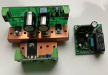
Unfortunately, I am not able anymore to purse some of my planed DIY projects and must part with components that I specifically acquired:
Here a set consisting of:
Paul Hynes Z100A regulator configured for 100-200V (it works also with single-ended valve designs!), I aimed at building with it a state-of-the-art tube preamplifier
The regulator can be enhanced with Paul Hynes constant current source CCS1A (mine is configured for 20mA but this can be reconfigured by changing a resistor)
Finally, a fully assembled K&K time delay module for delayed B+
I would require 185 USD including PayPal and shipping.
(I apoligize in advance if I ask noobie quiestions, but I'm a beginer in this matter)
I have a 1920s vintage speaker that is in a pristine condition! I intent to use this speaker with a small powered guitar amp that I've built. The guitar amp is called "ruby" wich is a 9v powered 1watt amp and it works well with 4ohm and 8 ohm speakers.
This vintage speaker is 1000 ohms and obviously doesn't work out porpperly with the guitar amp because of the impedance. So, I started to do some research and I found out that you would have to use a "step down" or "step up" impedance transformer. Now, here is when I hit the wall because its an unknown territory for me (yet)
I found out a website that allows you to calculate the type of transformer that you would have to use, but it seems that the results are not "realistic" but still, maybe I'm missing a few things.
What would you recomend to do in this particular scenario? again, its a small guitar amp (1 watt, 9V powered, works well with a 4ohm speaker) and I want to use it with this 1920's vintage speaker that is a 1000 ohm.
Hello everybody,
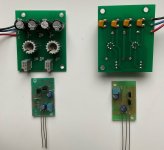
unfortunately I am not able anymore to pursue some of my planed DIY projects and have to part with some of the components I had specifically aquired.
Here a set for building an "Aunt Corey's Homemade Buffered Passive Preamplifier" that you can fine tune with Paul Hynes state-of-the-art regulators (ordered at +-15V). Modules were tested.
You have the option to further evolve the initial "AuntCorey design" (well, it is more than trivial) by using the second module at input before the volume control (pot). This would offer a "practicallyinfinite" input impedance with etremely low output impedance (this "design pattern" is used currently with great success by a comercially available solution).
I am requesting 165 USD including shipment and PayPal.
I wanted to show you my self-made streamer and DAC, which is built with Ian Canada components, and a few other things that I have developed myself.
above all i have been working on the cabinets, which are completely designed and manufactured by myself
This is now my fifth version, and has now been split into two cases, one case with the dirty power supply, a display is also built in, with which the actual streamer can then be controlled.
Everything is built like a power tank, the audio part runs completely on LifePo4 batteries with Superccaps, and can listen to music for a few hours with the best ESR values...
The complete structure is in dual mono, from dac 038Q2M dual mono DAC HAT is a very high quality DAC for Raspberry Pi. It uses two ES9038Q2M SABRE 32-bit chips, each operating in mono. The entire power supply is also dual mono. Each part has its own power supply, via LifePo4 like 325 Farad supercaps.
Still under construction; and I still have to finalise a few things 🙂
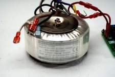
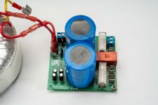
I have n.2 TR100A Hypex power trasformer, primary 115+115V center tapped secondaries 2x31Vac + 2x12Vac plus DC power supply module with DC speaker protection. 80€ each or 150€ for both.
I'm using a Raspberry Pi 4b and want to use it as a streamer. In the past i had an allo digi hat to a dac but now want to go full DIY. I want to separate the streamer and my DIY DAC into their own cases with separate power supplies. First question the clocks? Would you put those as a hat on the pi i was looking at the ian canada q7 reclocker or would you have that connected to the DAC board in the dac case? Icould use a hdmi i2s output board from pi and hdmi i2s input board on the dac board. I want to try an R2R board for DIY dac just t hear one.
I hope this makes sense, if not don't sling me pelters
hello everyone i want to do a fun and easy project an open baffle speaker, the first Diy project in my life, i saw the lii audio f15 and f18 and they amazed me by the dimension, my question is what driver should i take? the 15 or 18? my concern is that the 18 will be much bigger with the baffle created, is there a better driver between the 2? help me pick one, thanks!!
i am more oriented to the 15 as i read that is a little more equlibrate, and will not need an huge baffle
Im not no Im not using wd40
But ho do i keep my tires pretty?
How do i make rotten tires like new?
How do I make cracks in them magically disappear?
Hit mæ!
Cheers!
My amplifier ns20g suddenly powered off now when I try to turn it on it doesn't
I tired different power supply too but nothing works i left it for an hour and again tried plugging back not working
So I tried to open it up and check if something wrong with capasitor or ic but unable to locate the issue can someone help me with it
I recently acquired a Thorens TD 160 Super turntable with a Grace 707 tone arm. My problem is with the tone arm VTA all the way down the tail is still too high. I have the cartridge shimmed and am using three mats right now to compensate but this seems pretty kludgey. I know this was a popular combination - has anyone else seen this problem and come up with any other ways of addressing it? The platter bottom is around 7mm from the top of the unit, which I believe is correct.
Assume we're going to create a massive 3-way bookshelf with a tweeter, a dome midrange, and a large single 12" woofer, in the vintage manner of the Yamaha NS-1000, ADS L980, AR-91, etc.
In woofer selection, I found there's a very similar frequency response between the 12” woofer and the 12” subwoofer. Assume we’re going to cross the low-pass filter of the bass unit in the 300–500 Hz region, which is quite low when used together with the DOME midrange.
If the price of a 12" woofer and a 12" subwoofer is the same, as said earlier, their frequency response is identical, and with modern designs, they can both go flat up to beyond 1 kHz. Should we buy a 12" subwoofer instead? What are the advantages and disadvantages of using a 12-inch subwoofer as a woofer?
Lately I've done a lot of reading about how to decouple the power supply rails of opamps. But I'm still not sure, so now I want to know once for all, what is the right way to decouple the op-amps?
Let's assume I'm building a preamplifier circuit using a few NE5532 opamps (or similari). From that I learned so far the usual way to do this is to put two electrolytic capacitors at the the board, preferably close to there the PSU is connected to the board (to minimize that ripple current enters the signal ground). And then maybe also two smaller ceramic caps close to them as this;
Then, decouple each opamp power supply pins. This is what I'm unsure of how to do, but I be think there are three main options to choose from here. The first and simplest is to put a ceramic cap of 100nF between the two supply pins at each opamp. Like this;
The second option B is as suggested as almost all datasheet, one ceramic 100nF cap or so as close to each supply pins as possible, then to ground. The downside this this as that I be leave the signal and power supply ground should be separate at the board or very great care has to be taken with the layout, star grounding etc... So that ripple currents from the decoupling capacitor can flow through the signal ground.
The third C option I've seen is to put a capacitor as close to each supply pins as possible and the other rail, like this. This makes the distance from each power supply pin to decoupling capacitor shorter than in option A.
Option A and C has the advantages that no extra power ground is needed, simplification the board layout a lot. Question is if that is enough decoupling? Of course let's assume NE5532 (or similar BJT) op-amps and audio frequency use. And is C any improvement compared to A at all? Maybe overkill but ceramic caps are quite anyway.
With the gain off my subs have low humming bass and gets louder with SSF. If filter is all the clockwise it goes off but gain won't work can't barely turn gain up at all because subs are moving very low unless SSF is at about 35hz its the loudest with no gain
I have a Nady amp model xa-900 im working on. I need a schematic or service manual. I found it uses 4 each of kts301 thermostats. I found 1 open on each channel. I've replaced them but have both channels in protect mode. The +70 volt and -70 volts b+ is good in all collectors of output transistors. i have the +12 volts and +20 volt dc also. The pcb is labled +90 & -90 vdcom the rails reading +70 & -70. I would gladly pay for the schematic and cant find one anywhere. if anyone has it please contact me. Thanks Craig
Im new to car audio, and I'm getting two 10s to run on 1200w, planning on wiring parallel at 0.5 ohm
What are some quality amp brands? I don't know what's good and what isn't, I've heard good things about taramps, but others have told me they suck. Also, their only 0.5 ohm amps have 3000w or more, which is too much power for my application.
I bought this cable to redo signal wiring in my preamp due to the noise and crosstalk. The shield is going to be connected to the 0V of the preamp but only on one side so I am not creating any ground loops. My question is, how do I terminate the shield on the side that's not connected to anything? I do have to expose the signal wire and also strip some of the insulation from the shield but at the same time I assume that the shield should cover the signal wire almost to the end. I just want to avoid any strands touching anything and creating shorts. Any tips?
I repair the PS in this amp,all channels playing good audio but it keeps going in and out of protect.I did not see no dc offset on the channels .When in protect pin 3&4 goes above 4v in the 494
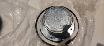
lp with regards to connecting a ribbon coil to my crossover.Should the coil be connected from the inner foil to the post positive or the outer foil to post positive? as you see in this photo the inner wire is connected on the left side and outer is connected on the right side. does it make a difference? the speaker crossovers were connected opposite.the positive speaker post goes to the left side. thanks for any help.
I recently received a TA7801 along with two subwoofers in the factory box, the amp didn’t go into protect, but had zero gate signal after further diagnosis, and I am unfortunately not experienced enough in amps to know where to trace it to. Any help would be extremely appreciated!
This is a request for anyone who has the the gatefold of this double LP in excellent condition.
Reason being I have the 2 LPs, what I don't have is the gatefold artwork it was stolen, a long story I don't want to get into. I will happily pay for a quality colour copy of both sides in a large size and postage in a stiff tube. I've always wanted to find a really good graffiti artist to do two walls in a music room. Down the road in Toulouse there are many.
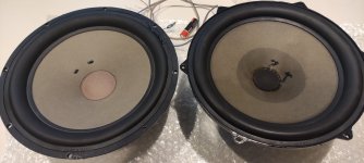
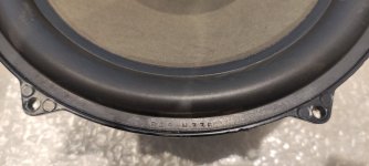
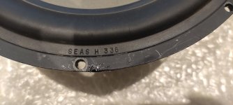
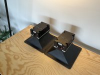
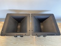
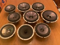
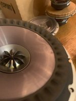
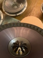
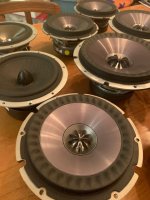
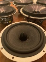
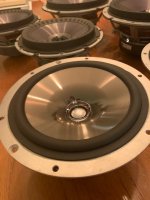
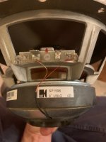
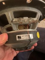
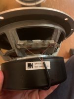
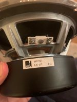
I have 8 NOS KEF Uni-Q coaxial drivers and one KEF LF driver that I'm looking to sell. In the bunch there are 4X SP1596 8in coaxials, 3X SP1588.2 6.5in coaxials, 1X SP1535 6.5in coaxial, and 1X SP1537 6.5in LF driver. One of the SP1588.2s has some minor blemishes on the cone (pictured below). They are very small and hard to see unless you catch them in the right light. I don't think they would affect performance. Otherwise they are all like new. Asking $75 USD each for the 8in drivers and $50 USD each for the 6.5in drivers. Volume discount if you want all.
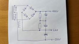
would you please have a look at my hand drawn scetch? I've got the power transformer of an useless, hence scrapped Hammond S6 chord organ. The HV secondary nominally is 285-0-285 Vac. My idea is to use it as the PT of a PP amplifier with 807's. The required screen voltage is 300 Vdc. Can I just connect the input choke to the CT terminal in order to get this voltage without excessive dissipation losses? How do I calculate this choke?
Just got in a new (to me...) acoustic musician amplifier by Behringer. The reason why I bought it is due to its separate channels for Instrument and Mic, along with separate digital effect systems on both channels. Plugging in for the first time, with volume set low, on the Microphone channel I notice whenever I connect the mic cable to the microphone the amp goes POW!. Whenever I switch the mic on/off slide switch - that one on the mic - POW! Different make model mic - same. I thought this is ridiculous...No other XLR input on anything I've ever owned has done this. I searched for the 48V phantom enable switch - no dice. Then I searched for a schematic - found something on my amps bigger brother.
Why did they think it was a good idea to pull both balanced mic lines high only on the XLR input? To +15, never mind 48 - a little something better than nothing? I dont mind going in and hogging out R7 and R5, but before I open the box, I'd like to know Why?
Uh, people dont use dynamic mics anymore? People dont mind a big "KaPoW!" coming from their amp when they switch their mic on and off? Some juice for the case when someone plugs in a condenser is better than none? Mics these days all have built in preamps, which need at least 9V phantom power - those old Shure SM57s arent the design target anymore?
Anyway, I can see what's the work to be done ahead of me. Feels strange to be this out of touch with modern, yet 15 year old mic input designs.
Maybe the LTP solution is simpler than normally supposed. The classic solutions are
Special power supply (e.g. negative leg)
Unequal load resistors
Active tail
Inductive tail
However musing over data sheets the thought hit me. The 6922/6DJ8/ECC88 really likes low Vp-k so why not just use that tube with a really large tail. It has low rp so doesn't need huge plate load and it likes running with Vp-k under 100V leaving plenty of voltage for a goodly tail.