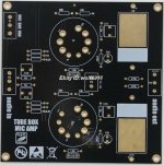
I bought a buffer kit based on Muscial Fidelity's X10 design.
I used a pair of 6N1ps (all I had) but otherwise built it as drawn below.
There was no onboard power supply but the seller recommended +-28v so I used a 24-0-0-24 transformer to give a raw +-50v (the Vigotronix pcb transformer has only 25% regulation) This seems a strange way to power a tube circuit to me and it could be redrawn and reconnected as a +80v supply.
Th heaters initially were powered from a 12v switch mode psu. They are wired in series and are floating so I tied one side to 0v with a 1k resistor. (switching noise was evident so will replace it with a LM338 based regulator.)
U1a's anode current was a lowly 0.13ma and the other triiode's was 1.5ma.
It measured well using REW - well below 0.1% at ~1v RMS into 4k7 and the gain was slightly greater than unity (by10%) Square waves at 1 & 10kHz were clean.
Comments are welcome, especially in respect of tubes and anode currents.
The Chinese seller's claims were, as always, exaggerated, although the 6N1p might not be a good choice.
The schematic is not OK , some kind of tube toy invented by that chinese firm .
B+ is too low , plate voltage is much lower than that and as consequence tube currents are too low .
The second triode has no cathode resistor . Both stages are amplifying but it has a large amount of negative feedback to achieve gain of 1 ... the only reason it has low distortion.
Even the negative feedback network is very weird
Last edited:
The MF x10 runs from a 12v AC power supply using voltage doubling so less than what I am using and still gives excellent performance according to their X10 brochure.
I did wonder how U1b was biased with no cathode resistor but the results speak for themselves although I have yet to audition it.
SPECIFICATIONS
Musical Fidelity reserves the right to make improvements which may result in
specification or feature changes without notice.
INSTRUCTIONS FOR USE
Input impedance 470 KOhms
Output impedance < 200 Ohms
T.H.D. < 0.005% 10Hz-100KHz
Frequency response +/- 0.2dB 10Hz-100KHz
Crosstalk better than -85dB 20Hz-20KHz
S/N ratio better than -98dB Unweighted
better than -112dB 'A' Weighted
Power requirement 12V AC 500mA (via mains
adaptor supplied)
Valve type 2 x ECC88
Dimensions (mm) 110 x 110 x 220 (W x H x

More measurements:
I am using a 4amp switch mode psu for the heater and noise was fimding its way to the output.
In fact I tried two - one showed ringing spikes around 50k and the other, around 150k..
So next I made a filter consisting of two series connected 3 terminal signal filters of 10n - 2.2uH - 10n, with the second one paralleled on it's input and output with 10uf Tants.
This reduced the noise by 15db but there is still a spike around 20kHz.
Also attached a 10kHz square screenshot from Picoscope.

Look for the real schematic, thats easily found on the www. The psu uses 12 volts AC. This is used to regulate to 12 volt dc for the glow of the tubes in series (2× 6 volt). Also from the 12 volt Ac there is a voltage multiplier and discrete regulation that creates + and - 35 volts. I still have the little darling and must say that the quality is great. I've exchanged the capacitors to decent MKP caps, and the tubes to nice Philips types. You best use it between a CD and (pre)amp.
I do have the original schematic but I didnt want to just copy MF's design exactly. (I read that they wanted to avoid lethal voltages inside the buffer)
The sellers listing did probably mean +-24 when it stated 48v but I decided to go with +- 35v.
My initial testing with a pair of 6N1ps gave slightly better results when the supply was increased from +-30 to +-40v.
The buffer is for a passive preamp for which a low output impedance is now needed to drive my Naim IXO active crossover - 4k7 minimum input impedance.


Any results/details to share?The correct 14v gave slightly worse results.
Comparison of 12,2 and 14v heaters. (tubes with series connected heaters)
More info on the benefits of using a PCC88 over a 6DJ8 / ECC88 - link below, but conclusion is that they work well and will last longer on 6.3v. (I'm using DC)
https://www.watfordvalves.com/product_detail.asp?id=7789
You can see a blip in the noise at 50Hz so I need better filtering in the HT.


More info on the benefits of using a PCC88 over a 6DJ8 / ECC88 - link below, but conclusion is that they work well and will last longer on 6.3v. (I'm using DC)
https://www.watfordvalves.com/product_detail.asp?id=7789
You can see a blip in the noise at 50Hz so I need better filtering in the HT.
- Home
- Amplifiers
- Tubes / Valves
- X10 clone tube buffer with 6N1P