For Sale Curve-traced 2SK170-BL Toshiba JEFTs for sale

Up for sale are quads of new original stock (NOS) genuine guaranteed authentic Toshiba N-channel 2SK170-BL audio JFETS.

The Idss (drain current for zero bias) and Yfs (transconductance @Idss) were recorded under constant ambient conditions by curve-tracing a large batch (single lot#) of BL-grade 2SK170 JFETS sourced 10+ years ago from Spencer. The Yfs vs. Idss distribution for this batch of transistors is shown.

The JFETs were sorted into individual bins of 4 (quads) with highly similar measured values for Idss (difference < 0.03 mA) and Yfs (difference < 1 mS).

If interested, please consult THIS LIST for available devices and send me a PM indicating the desired quad(s) and your shipping address.

The cost is 28€ for one quad and 24€/quad for two or more quads + postage.
The FETs are individually labeled and shipped in anti-static bags.
Postage by international priority mail (no tracking): 4.45€ for EU/UK, 5.35€ for US/America and 7.35€ for Asia/Australia.
Postage by registered mail: 9.80€ for EU/UK, 12.30€ for US/America and 14.00€ for Asia/Australia.
Payment by PayPal (I will cover fees).

Attachments

  • IdssYfsDist.jpg
    IdssYfsDist.jpg
    123.8 KB · Views: 262
  • 20231109_130754469.png
    20231109_130754469.png
    779.4 KB · Views: 261
  • 20231109_130902739.png
    20231109_130902739.png
    820.8 KB · Views: 208
  • 20231109_131426500.png
    20231109_131426500.png
    737.6 KB · Views: 183
  • 20231109_131712438.png
    20231109_131712438.png
    609.6 KB · Views: 178
  • 20231109_131933743.png
    20231109_131933743.png
    721.4 KB · Views: 227
  • Like
Reactions: Eric

Advice on noise source in active crossover?

I have been using an old french 4 way active crossover for a long time - Power FEP 204 - and it works very well, except for the extra hiss which it introduces into the system. I had some very good advice on solving a similar issue with a Linsley Hood integrated amplifier - changing some old 1980s op amps did the trick. This circuit contains six RC4156DB and one R4559NBS. Does anyone have any views on these or anything else as a possible culprit?
IMG_0047.JPG
IMG_0046.JPG
IMG_0045.JPG

Denon PMA320A interesting bias circuit

Dear Members,
I have an old, simple PMA320A in wich I made some repairs because of age and the all-time failing phono stage. I must note that the +15 V supply have failed and it was around +30 V of +VCC supply on every opamp and the input selector for maybe years (the slight noise on every input selection was there with this amp since years and it is cured with the right supply voltage) and every parts have survived it, with no apparent problem with operation!
So back to the topic, this is a revised amplifier (denotes "A"), with opted out over temperature protection and a slightly reworked PCB. The topic is bias circuit. Let's see:original bias circuit.JPG
This is a bit uncommon biasing, TR521 serves as a diode and in series with TR509, forms a Vbe multiplier with an added extra thermal compensation of the Vbe multiplier. The two transistors are mounted near the heatsinks and covered with some compound to help heat detection (not the most beautiful solution), as can be seen on the left side of the circuit:
partslayout.JPG
Leftside.jpg
Until this point everything looks fine. But let's see left side on the PCB:
missingTR.jpg
As You can see, somebody is missing. Only one transistor is mounted (the Vbe multiplier), the other holes are unpopulated. See the PCB side, it is made this way in the factory, and one can quickly realise that the drawing is faulty, there is no connection to the (wrongly aligned) common B-C legs:
soldering side.jpg
However the B leg of TR509 goes down the way on the PCB, where...
diode.jpg
..it arrives under TR515 driver and a diode D509 (not visible on the shcematics anywhere else, so maybe the solution existed before..) is placed here (it is already removed by me). Let's see it on drawing, what Denon did:
Modded bias circuit.jpg
(The resistor next to D511 was also altered to a smaller value not visible on the picture).
So it looks like somebody made an error, also tried another solution for heat compensation, and the two things have mixed up not only in PCB, but in schematics too. And indeed, the thermal point and biasing was so different between the two sides that I started to suspect some nasty errors around, but finally I found this difference. It is very interesting for me, that what and how happened. The layout can be easily converted back to the original solution, the extra transistor can be added (I have used an european made one because the layout -EBC- fits the right way with the badly aligned PCB for layout -BCE-) and the diode can be left unpopulated and linked.
Maybe some trial test PCBs, maybe went out for production? I have seen few images from other 320A amps and those all have this weird solution.
Any comments, or ideas?

Group buy for Augerpro ScanSpeak waveguide (circular version)

NOTE: Unless indicated otherwise, I will keep a small stock of these waveguides. If you want the waveguides, just follow the steps below.


This is a group buy for the waveguides designed by augerpro that will fit the "larger" Scan Speak tweeters. This group buy is for the circular type, made from solid aluminium, black anodized. The dimensions are very similar to the WG148 waveguide.

These waveguides fit the Scan Speak D3004/66x0 (textile and beryllium domes), the R2904 ring radiators and most likely also the R3004 ring radiator. Just replace their stock face plate by the waveguide. The waveguides might possibly also fit some of the other Scan Speak tweeters, but I have not seen how these tweeters look behind their face plate, so I can't promise.

A 3D STEP file of the waveguide is available here in the attachment. I also have some measurements of this waveguide, along with the elliptical version A (augerpro) and the WG148 here.

Price will be CHF 95 per piece (about 85 Euro). Add shipping costs, customs fees, taxes, etc.

I'd prefer shipping with Swiss Post.

I have 10 pieces of these waveguides. First come, first served.*

I usually keep a stock of these waveguides. If they run out, I can always get a new batch.

To sign up to this group buy:
(1) Reply to this thread and add your diyAudio name and the number of waveguides you want to the list.
(2) Send me a PM with your full name, shipping address, telephone number (optional), and email address.
(3) I will send you a PayPal invoice.
(4) Once I received your payment, I will send the waveguides to you.

(*)Notes:
  • If you are looking for the waveguides used in the Open Source Monkey Coffin, this is it!
  • I currently have a bunch of waveguides from the third batch in stock. Once they run out, a new batch can be done without too much trouble.

Attachments

Sony TA-N55ES - Right channel sort of dead - trying to repair

Hello everyone!
I may need some advice!

Left channel works good, sounds good.

Right channel has noticeable noise and very low volume - music comes trough. But the volume of the noise and the music is the same regardless of the volume knob.
Speakers A or B - same result


What i did so far:
I visual checked the boards for any visible damage - nothing
Replaced The STK3102 chip, and idling adjustment to 7mV on both channels - This one didnt help. The status of the amp is exactly the same as before.
Without any source or speaker connected, I measured the 7mV on the left channel and ~55mV on the right channel.

I measured every resistor and capacitor (except the selector board) - I found a few not matching the service manual, i will make a list later.

According to the symptoms what should i check next?

Choke substitution in Dynaco ST35 - 2.0H vs 1.75H

I'm gathering components for another D Gillespie EFB ST35 amp - unfortunately not as simple now given the resourcing effort underway at Dynakit parts. A question on the C-354 choke https://www.dynakitparts.com/shop/c-354-choke/. Could a 2H choke from ThermionicLabs by substituted here. https://www.thermioniclab.com/en/po...hoke-2h-250ma-for-skunkie-designs-kt-120.html. The resistance is 66 own vs 62 for the C-354 and current rating is above the original. I've seen posts about using 1.5H Hammond chokes ps://www.hammfg.com/electronics/transformers/choke/153-159 - making me wonder if the higher .25H rating is fine if a Hammond lower .25H works or if any changes are suggested in the power supply for the substitution. Thanks

Pro-ject Debut III Speed Box

Does anyone have the circuit diagram for the early Project Speed Box?

Mine has stopped working, the platter won't turn at all and both LEDs are illuminated all the time.

I've attached an photo of the front of the unit for reference (power pulled so no LEDs on), and a photo of the circuit board.

On initial investigation the transistor circled gets very hot very quickly after power on, so my guess is that'll be the obvious place to start. But I need the schematic to get the transistor part number and see what it is exactly it does.

Thanks in advance.

Steve

Attachments

  • IMG_0814 2.JPG
    IMG_0814 2.JPG
    291.1 KB · Views: 390
  • IMG_0813.JPG
    IMG_0813.JPG
    329 KB · Views: 369

I need help landing a plane without having a pilots licence!

I finally bought an oscilloscope and I really need help setting up a new laser on my arcam alpha 7 & 8 CD players.

They both have a KSS240A laser.
I have not got a clue of how to use an oscilloscope and I do not see any potentiometers on the motherboard of the cd players. I basically need to see the eye pattern.

Can I ask, are both tracking and focus adjustments done with the potentiometers on the laser ?

Again, I have never used an oscilloscope and I have attached photos of my oscilloscope. Any chance someone can give me some brief instructions in the same way you would do if a pilot of a plane had gone and a stranger got in his place for the first time and trying to fly it with no experience whatsoever.

So basically something like turn this knob to the right then plug this in there turn that that way etc. I do not need to know what I am doing as long as I can see the eye pattern on the screen. I have bought 5 of the same cd players so if I manage to fix one I will sort out the rest as they all have the same issue bad laser!
I did actually manage to save one as it just had smoke on the laser and by cleaning it it played like new but the other ones are very sensitive to vibrations and the laser seems to be at its end.

Thanks in advance.

Attachments

Will this circuit work as I plan? 4 input SE audio switcher with connected input grounds.

Here's what I've got. I'm mostly worried about the ground from all inputs connecting together. Is that going to cause any problems?
Otherwise, I'm not 100% on whether or not I've connected the volume pots correctly, and if there will be audible SQ problems from using a single relay per input, rather than per channel.
Hopefully my schematic is legible, I don't have experience with this.

Schematic_switcher_2024-04-13-2.png

Marantz 4400 modern or vintage speakers...

Hi,
a friend of mine is looking for speakers for his Marantz 4400. He doesnt really know about impedance or what it means and the speakers he is currently looking to buy are kef R5 meta. The kefs are listed as 4 ohm (min 3,2) and an efficiency of 86db. I'd say the 4400 could drive them but it's not ideal.
What would you say and if you had to choose what would you consider a perfect match for a medium sized room...?
I personally would say JBL L100 might be a good choice but thats just based on ...I dunno...probly gut feeling. Does the 4400 benefit from modern speakers? My feeling sais vintage amp likes vintage speakers but again thats just a wild guess.
Thank you so much for any input!
Arne

Motional Feedback that can potentially be used for planar magnetic woofers ...

Well, i received a prototype of a kit that used light instead of the other options to create a signal to make a MFB driver (Sander de Jong).
i used a regular woofer here since i am new to using in this case the circuit, a scope, and the camera to film it.... so i though lets start off with a regular ported woofer that i just plug off 🙂 (hopefully)

must be clear we had random results in what it does and if its usefull, depending on the type of panel.... so we are not sure. but for dynamic woofers it works for sure ! here a crude method and way of doing it.... by a newbie

Login to view embedded media

Pioneer SX-680 FM Issue

Hi Members & aficionados of Pioneer equipment, expecially FM lovers welcome to reply.

I am having nagging issue with my SX-680, the LED Stereo light is not coming on, I can listen to FM stations but it is for sire in Mono mode. When I press the Mono switch there is silence all across the FM band.

The Voltage of Pin 6 of IC PA1001A is stuck at 7.3 Volts and it does not vary once I am locked on a FM station.
The meter is showing signal strength.

TP1 Sawtooth is found but a little distorted.
Lissajou figure is also pretty good.

For your reference I am attaching the voltages I found on the two IC's.

I am suspecting a bad PA1001A.

Thanks

Attachments

SissySIT R.3

...... or - Look Ma, with no hands,Beast with thousand iterations!!

:clown:

Logic demands that main schm is here, and all future edits, if and when needed

Few facts, for start, so when you ask, I can point you to this post:

Rails - regular FW Format - in my case that is 300VA Donut per channel, 18+18Vac secondaries, two Graetz bridges per Donut

Iq - 1A7 to 1A8 ...... so dissipation per channel aroundish 80W

Autoformer - Cinemag CMOQ-4HPC

OS - generic ( means don't care which Factory) IRFP9140 and THF51S

Keratherm 86/82 pad for Mosfet, no-name silicon sheet for THF

so, schm (as you can see, it is in fact simplified LuDEF ....... which is logical - this exactly lead me to LuDEF and few other Bstrd amps; stay tuned :clown: )

edit on 15.09.2021 - few general setting procedure tips and tricks:


-will not teach ya how to solder everything properly - as always -Assembly of Japanese Bicycle Require Great Peace of Mind

- one tip -SIT gate resistor - R126(226) - best to put shortie (0R) in pcb position, and put resistor itself heatshrinked to end of tiny wire and solder ditto to SIT gate

-prior to powering up, be sure that you have trimpots set properly:

P102 (P202) - irrelevant
P101 (P201) - set to max; confirm with ohmmeter across R104 - in vicinity of 28R
P103 (P203) -irrelevant
P104 (P204) - set to min ; confirm with ohmmeter - improvise where to put probes

- jumpers JP101/201 - open/not mounted

-as always - best to work with one channel connected to PSU at time; in fact - first step just one channel , in second step - you can freely leave powered/connected already set first channel

- one VMeter across output ( DC offset) , second VMeter across any of current sense 0R22 resistors; use mini-clips/probes

- no load on output, input shorted to GND

- power up thingie; observe DC offset - it will rise slowly and everything up to several volts is normal in this moment

observe VMeter across 0R22 resistor - it will be Dodo reading for some long time; after 60-90-120sec - if you don't see any substantial reading , start fiddling with P104 (P204), one turn at time; of course - you did remember where you rotate itr to set to min value, now rotate in counter direction; - don't ask me which - I don't care, I can't remember, simply because I'm always trusting in DMM, not in my memory how to orient damn trimpot to have screw in proper place ....... and my logic what needs to be decreased and what needs to be increased is always ooked, vs. overall consensus :rofl:

allow 30sec or so between 1-turn steps, to observe when and how much mV you're getting across 0R22

goal is , , say for 1A8 of Iq - 1A8 * 0R11 = 198mV

keep fiddling to get mV creeping up, and once when you see steady rise for each turn, set da thingy to - say 160mV

once when you're there - fiddle with P103 to get as close to 0mV of output DC offset

that would be preliminary setting of OS, now to input buffer setting :

- power off , put mVmeter across R106(206) test pins ; put second mV meter on jumper pin marked "B" and GND

power on, fiddle with P101 to set 20mV across R106(206) ; done - fiddle with P102(202) to set as close to 0mV for buffer output offset ( second
mVmeter) ; when done - power off, close jumper


*************** connect second channel to PSU, repeat entire procedure******************

when done with both channels , power on , re-set Iq of both channels to have 1A8 (Square Law OS is crazy thing) somewhere in temp equilibrium, check output DC offset

slide of both Iq and DC offset - cold vs. hot - is really minimal, but I'm mentioning thermal equilibrium more thinking of importance of final temperature of heatsinks - observe, observe also temperature of outputs , that will give you info/confirmation how good and uniform is thermal interface between parts and heatsink

**************

when done, connect signal, speakers, flip da switch, and enjoy

don't forget Da Porn - no Porn, no Glory

:cheers:

Attachments

  • SissySIT R3 schm.png
    SissySIT R3 schm.png
    56.2 KB · Views: 6,020

Center channel

Some cars have a small center channel speaker in the middle of the dash. I intend to do away with the factory amp in my car and I'd like to keep this speaker. But it seems to me that combining L+R (simplest thing to do) would mess with the stereo imaging. I'm thinking that the center should contain only what's common to both channels. Anybody have an idea about how OEM's typically implement this?

Arcam p49 not powering up

I have two Arcam p49 Power amp that will not power up. Prior to this they were stored … brought them back to the living room set up
In duel mono… after 20 mins left hand just went out …
Took out system reverted to stereo one amp
configuration, around 20 mins that one also failed to power up!
Set up Mark Levinson 326S preamp
Can anyone explain what may of caused this to occurred, and what the fix is?

DIY 300B Monoblock

Hi folks,

Following my first 300B monoblocks built in 2021, I'd like to share my latest 300B monoblocks built in 2023.

Features Highlights:
-5.5W effective output from each channel
-Each block contains an 100VA Power transformer, an 10H choke and an 35W output transformer
-All of the B+ and filament voltages are regulated by LM317
-Soft start for filament voltages (to prevent inrush current from damaging the filaments)
-starts from 1.9V to 5V and 6.3V in 10 seconds
-Delayed soft start for B+ (to pre-heat the filaments before supplying B+ for prolonged tube life)
-starts from 20V to 376V in 30seconds after 30seconds delay upon power ON
-Timer function achieved by 555 IC
-Solid state relay for B+ for prolonged life
-Zero-crossing detection (achieved by the solid state relay)
-Plenty of RC snubber networks used to reduce damping and noise

1695877696107.png


1695877729232.png


1695877746947.png


1695877846175.png


1695877898470.png


1695877915140.png


1695877948727.png

Help with choosing capacitors for an Amplifier

I have two Arcam A22 amplifiers with same issue. The capacitors seem to have blown as in the attached photo.

The capacitors say on them:
Aerovox ALC10A 103DF063.

Can someone help me what I need to buy I made a search online and it brings me on Mouser electronics or are Components in UK for a KEMET capacitor with slightly different number.

Also as this seems to be common amongst this particular amp can you recommend any capacitors that hopefully last longer?

Thanks

Attachments

  • IMG_7942.jpeg
    IMG_7942.jpeg
    288.6 KB · Views: 141
  • IMG_7943.jpeg
    IMG_7943.jpeg
    272.1 KB · Views: 140

How critical is track and wiring length matching for tube-based LTP differential pair?

Hello !

I am building an LM317-based CCS board for a tube LTP and I have adjusted the differential track lengths to within a millimeter with serpentines as seen in professional pcbs (see image). This was mainly as an educational exercise but I figured why not put all chances on my side since it is easily done.

Capture d’écran 2024-04-12 140457.png


Note that the board hosts two independent channels and the lengths are adjusted for the +/- tubes in a channel but the channels don't have the same lengths between them - One is 10mm longer, which is 33% more with respect to the other channel. The adjusted tracks start from the on-board differential balance adjustment trimpot; everything from that pot's wiper to ground is common-mode.

As I understand it, differential routing length trimming is critical when dealing with high-speed circuits, where the tracks being much longer than the signal wavelength they carry behave like transmission lines. Our audio circuits are not high speed but tubes can oscillate at HF. The current project is an input stage using triode-connected pentodes, I read these are prone to oscillate up to the MHz range? Also the LM317 itself can oscillate.

So back to the current question, how critical is track and wiring length for this project and tube differential pairs in general? The board doesn't host the tube sockets and so if perfect balance is needed the wiring to the +/- sockets will of course have same lengths. Now that I'm finished writing I realize I should be talking about impedance matching, but in this project's context tracks and wires have same width/gauges and are far apart, so parasitics are mostly equal and signal cross-coupling should not be an issue... I think 😎

Thanks for any insigths!
Joris

Beogram CD7000 as a separate DAC

Hello
I am asking for your advice on the following issue. I have a Beogram CD7000 with a damaged mechanism and I would like to connect it as a separate DAC using the original CD7000 power supply and analog stage. If it succeeds, I will probably change the analog stage to a tube one. The problem is that the CD7000 has strange controls - the TDA1541 power supply voltages appear on its pins only after pressing the Play button and if the system does not detect activity, they disappear after about 3 seconds. So the question is - how to lock the microcontroller so that the supply voltages remain active after turning on the CD7000? Looking at the attached block diagram, it seems natural to have a permanent short to ground on pin 19 of IC4. Is this a good idea or should something else be done? Thanks for your help.
DIagram CD7000_2.jpg

Diagnosing Tube Amp Problem

I have a Decware zkit that has worked fine until recently; I changed the input tube to a 5670 using an adapter and the amp suddenly started humming and one channel died. After going through and testing components it seems everything is fine but it just makes a loud digital popping sound from both sides (sounds like the old Atari “tank plus” game).
I can’t rationalize what it could be other than the tube socket was damaged by the adapted pins, but when I removed the socket it appears to be fine, with connection from each pin socket to lug, and no cross current.
The power transformer seems fine, and the power supply section is producing appropriate DC voltage. I’ve tried different tubes with the same effect.
Now I am looking at the output transformers- I get continuity across the positive and negative speaker jacks on both sides. Are my output transformers blown?

2A3 interstage headphone amplifier?

Looking for schematic, design and/or plans for a 2a3 interstage headphone amplifier. I think SonnyMarrow posted one he made but he couldn't post the full schematics because it was similar to Eddie current studio T. https://www.diyaudio.com/community/...stage-transformers-venue.390795/#post-7136376

Does anyone have one they built or know of that sounds good they can post?

I am interested in using tamura and electraprint output transformers in this project.

Thanks.

How to connect test leads to TrueRTA Oscilloscope on laptop?

I'm new to making measurements of audio equipment. I'm in the process of adding an amp, speakers and a DSP to my Harley and have been enjoying making some measurements. I've got levels set using a hand-held oscilloscope, and have made some measurements with my PC running TrueRTA. I've got a Behringer ECM8000 mic connected to a Behringer USB Mixer as an input for the audio measurements.
The question is: How do I use the oscilloscope function on the RTA? Meaning, how do I connect test leads to the laptop? I'd love to be able to use the laptop oscilloscope vs the hand-held because it has a nice big display. I know there are a bunch of PC-based oscilloscopes out there that come with a USB interface, but is there a generic USB interface that would work with the TrueRTA software? (Yes, I've asked them, but have had no response).
I'd like to be able to go from an audio measurement directly to a oscilloscope voltage measurement so I could see if there's clipping at various frequencies based on the information from the RTA.

Any Bluesound Node 3 users out there?

Just received a Bluesound Node 3. I can not get it to connect at all. It keeps telling me error, try again. I did many times. Contacting web site was not helpful. Basically notes covering the same process, no help.

I don't know if there is a problem, instructions are very simple. I don't know if it's defective and needs returned or what.

Thought I would ask here before returning it. Anyone have suggestions?

Russell

For Sale One meter pair of Homegrown Audio Pure Silver XLR cables

Sold

Asking $100 $80/ or best offer, including USA shipping.

One meter (41 inches overall length) pair of Homegrown Audio Cables, XLR terminations, that I assembled years ago from their kit offerings.

Seven stranded pure silver Litz braded wiring (2 per positive leg, 3 in ground leg). Silver plated Neutrik XLR terminations. Cardas quad eutectic solder.

USA shipping only.

IMG_3749.JPGIMG_3751.JPGIMG_3753.JPGIMG_3754.JPGIMG_3755.JPGIMG_3756.JPG

Audio-Technica AT-1005 II Tone Arm - Broken Connection

Hi - I came into possession of a turntable and it has an Audio-Technica AT-1005 II Tone arm, which seems to have its connection broken. I have very limited knowledge of any of the equipment but am keen to get the turntable working again. Does anyone know if this is something I should be able to fix at home or does it need more expertise then this, if so can anyone recommend anywhere in London that could fix this at a reasonable cost? Thanks

image1.jpg


image0.jpg

3D printing core for field coil speaker

Hi everyone .
I recently discovered what you can read on the link page, it is in Italian but just use the translator.
https://www.replicatore.it/elkem-ha...silicio-per-la-stampa-3d-di-motori-elettrici/
there is talk of a method for printing the core of electric motors in silicon steel.
I wonder if it was possible to use this product to print the core of a field coil speaker.
of course you have to know the costs otherwise it's not feasible, I sent an email but didn't get a response. perhaps it is not yet on the market or is for the exclusive use of industry.
do you know something?

For Sale Tetra Phono All-in-One

SOLD!

I got this from here but I have too many phono projects at the moment.

EDIT: Tubes included are matched pairs of NOS RCA 5963, NOS GE 5751, Chinese 6N3, NOS HP/RCA 5963.

I have squeezed in the package 4 unpaired tubes but measured (not by me): Mullard ECC82/12AU7, RCA 7326, RCA 12AU7A, Beckman ECC82.

Attachments

  • 2024-03-07 17.32.39.jpg
    2024-03-07 17.32.39.jpg
    384.9 KB · Views: 130
  • 2024-03-07 17.34.48.jpg
    2024-03-07 17.34.48.jpg
    363 KB · Views: 127
  • 2024-03-07 17.37.44.jpg
    2024-03-07 17.37.44.jpg
    304.5 KB · Views: 117
  • 2024-03-07 17.40.17.jpg
    2024-03-07 17.40.17.jpg
    396 KB · Views: 110
  • 2024-03-07 17.42.31.jpg
    2024-03-07 17.42.31.jpg
    341.3 KB · Views: 112
  • 2024-03-07 17.43.28.jpg
    2024-03-07 17.43.28.jpg
    540.6 KB · Views: 124
  • 2024-03-07 17.46.26.jpg
    2024-03-07 17.46.26.jpg
    621.2 KB · Views: 140
  • 2024-03-07 17.50.09.jpg
    2024-03-07 17.50.09.jpg
    420.6 KB · Views: 135
  • 2024-03-07 17.52.40.jpg
    2024-03-07 17.52.40.jpg
    677.1 KB · Views: 143

Lateral CFP variant with small gain for better headroom.

Lateral_CFP_variant.png


I attempted to overcome the headroom issue with a CFP using lateral MOSFET output devices. The normal CFP circuit limits the driver excursion to the gates/bases of the output devices, but lateral MOSFETs have maybe upto 10V of Vgs which restricts the swing for a CFP arrangement. The normal CFP-with-a-little-gain arrangement dissipates quite a lot of power in the feedback resistors as they have to be low impedance (they go to the emitters of the driver transistors).

So I arranged feedback to bases of differential pair drivers, R6, R7 above - higher impedance and only one divider needed.

The emitter tails of the pairs need more current when the relevant output device is conducting more current - but the low transconductance of laterals means the Vgs is a reasonable proxy for this current, and this appears across the 150R CFP resistors R30, R33. So the voltage across these resistors is converted to a current by 10k resistors R1, R2, and bounced off current mirrors, which multiples the current about 45 times before being fed to the relevant emitters. Note that this method only responds to current, independent of the output voltage, so should handle reactive loads well.

This current feedback loop might be unstable unless the system is biased into conduction appropriately with R12 - at least this works in simulation (more analysis needed) - and this can be adjusted to set the output device currents - it would be better to have an adjustable current source/sink rather than resistance for this to be independent of supply voltage.

Diodes D1 and D2 prevent reverse biasing the transistors in the pairs during clipping, the 470pF C1 and C3 prevent oscillation (not sure how that works yet!), and R17 limits clipping artifacts.

The actual choice of transistor for the differential driver pairs needs to take account of their dissipation, I've must modelled with small-signal devices. And lots of component values can probably be optimized.

Here I wrapped an LTC6090-5 high-voltage opamp around as input and VAS.

As laterals are used there's no need for source resistors to further improve headroom.

Whether this is a workable scheme in reality I don't know yet, but I hope to build this up at some point. It probably already exists of course, nothing new under the sun, but I didn't seem to find much about CFP's with gain using laterals when I searched.

Power Transformer

I needed a Power Transformer for a project, with 14 secondaries.

These dudes ( https://x.alibaba.com/AwA6KK?ck=minisite ) made me one, and finished it 24 hours after I paid. $110 for 2Kva.

Comms were great, and they patiently delt with my alterations.

I haven't tested it yet as it's in transit.

I'm not affiliated with the company in any way, just thought it may be helpful to some.

Attachments

  • Alibaba1680178461.jpg
    Alibaba1680178461.jpg
    192.5 KB · Views: 197
  • Alibaba1683902521.jpg
    Alibaba1683902521.jpg
    308.6 KB · Views: 201

Best economic DAC to play upsampled music to DSD 512

Hi,

I play music with Daphile and a Topping E50, upsampling all songs to DSD 512 through C-3PO.
I know AKM chips can remove all filters when playing DSD, so they should sound better in this specific case compared to Sabre chips.

Will an E30/E30ii play better? There will be difference between the E30 (single chip) and the E30ii (double chip)?
Any other economic alternative? I can consider OEM boards too.

Thank you in advance,

Roberto

DIY DAC with premade PCBs, some questions

Hello,

i would like to know if people who tried to build a dac with multiple standalone pcb's (spdif to i2s converter board, i2s to dac board... etc) what the expierence is and specially if they compared these dacs with readymade dac's, is it worth it?
Are there particular links/pcb's/vendors you can recommend?

in my mind i have a concept of -> usb to i2s board -> i2s to NOS dac board plus some nice power supplys, preferably battery or super capacitor
i also saw the protodac (its a nos dac) which i thought of making my own pcb with amanero card support, might be even the perfect starter project

best regards

I2S and Multi channel audio

I think I’ll be needing few experienced help here It is more an intellectual personal challenge than a real project, but I try to fill the gap between evaluation boards like RPi and OrangePi and Full Digital amps like those developped by TI and ST, in the context of multi amplified speakers (with Crossover function in soft DSP).

I2S is the common input for the FDA chips. My understanding is that I2S can only address 2 audio channels, and this is a roadblock on my way.

How to control several I2S inputs from one single board (RPi or other) ?

I have not seen additional modules to add more I2S connections.

I have not seen ways to multiplex more than 2 channels on one I2S...

With USB, it often looks like RPi USB => USB decoder=>SPDIF=>I2S (and only 2 channels...): lot of transformations, risks of time mismatch, lots of cables for 8 channels (ex of 2 x 4 ways speakers)...

I'm surprised as many applications are now 7.1. HDMI has 8 channels...

Do I work with wrong assumptions?

Do I take the problem in the wrong way? Other ways to explore?

A Totally Different Input/Driver Stage Has Any One Tried It??

You Can DIY! Meet the Pentriode​

August 4 2022, 10:10
Shortly after my first tube audio article, “The Mu Stage,” was published in 1993 in Glass Audio magazine, I developed a simple circuit that I called the Pentriode. I even wrote a tentative article about the Pentriode in 1995, and I considered submitting it around that time but somehow never got around to it. I finally decided now was the time for me to share a blast from my past as I show you the Pentriode, this time with additional information.

The Circuitry
Probably everyone who reads anything about tube audio circuitry knows that a pentode can function as a triode when its screen grid (Grid 2) is connected to the plate — see V1 shown in Figure 1. When triode connected, many pentodes can be outstanding very linear triodes.

https%3A%2F%2Faudioxpress.com%2Fassets%2Fupload%2Fimages%2F1%2F20220728060718_Figure1-DIY-Meet-Pentriode.jpg
Figure 1: This is a triode-strapped pentode connected to a cathode follower buffer
The Pentriode is formed by making one simple change to Figure 1: Connect V1’s screen grid, not to V1’s plate, but to the cathode of cathode follower (CF) V2—see Figure 2. In Pentriode mode, V1 essentially operates as a triode, but its screen grid current no longer burdens the plate of V1. Instead, CF V2 provides all current to V1’s screen grid. Pentriode mode brings nice advantages.

https%3A%2F%2Faudioxpress.com%2Fassets%2Fupload%2Fimages%2F1%2F20220728060756_Figure2-DIY-Meet-Pentriode.jpg
Figure 2: This schematic shows the Basic Pentriode (circa 1995).
Pentriode mode is not strictly triode mode nor is it pentode mode. It is also not “ultra-linear” (aka partial-triode) operation. I had to come up with an entirely new name for this circuit, and the name Pentriode seemed appropriate. Pentriode mode is definitely most like a triode mode, with the same (or closely the same) mu and gain as the pentode would have in conventional triode connection. In fact, designing a Pentriode stage is as simple as designing a standard triode stage, the only extra part being the addition of a simple cathode follower.

Cathode follower V2 can be any active device, including a triode CF or a pentode CF (my favorite follower for audio — see Figure 3). There are also several other options: You could make a hybrid Pentriode by using a field-effect transistor (FET) source follower in place of V2, or a bipolar junction transistor (BJT) emitter follower, or a Darlington emitter follower, or an insulated gate bipolar transistor (IGBT) emitter follower, or a Sziklai pair follower, or an IC voltage follower, or a current follower, and I’m sure several other follower types. V2 could also be a follower consisting of a vacuum-state device, solid-state device, gas-state device, or any state device.

https%3A%2F%2Faudioxpress.com%2Fassets%2Fupload%2Fimages%2F1%2F20220728060828_Figure3-DIY-Meet-Pentriode.jpg
Figure 3: Here is an improved version of the Pentriode.
By the way, it is my standard practice to use grid stopper resistors for every control grid and every screen grid. Suppressor grids don’t need a stopper resistor. In audio applications, I normally use a value of 220Ω for grid stopper resistors.

Pentriode’s Benefits
It is important to note that some pentodes really excel in Pentriode mode, more so than other pentodes. Some pentodes give even less distortion in Pentriode mode than when the pentode is connected in standard triode connection. It would be nice if we could tabulate a list of the pentodes that excel at Pentriode operation.

It is also possible to make a Pentriode mu stage, which is probably my favorite type of mu stage. It has all the advantages of mu stage operation including wide bandwidth (BW), low distortion, low output impedance, plus the advantages of Pentriode operation. A practical example is shown in Figure 4. With regard to Figure 4: 1) The purpose of the 27kΩ resistor is to drop a few DC volts so that V1’s screen grid voltage is the same as V1’s plate voltage, to closely emulate triode operating conditions for V1. 2) When a 6AC7 tube is used for audio, its heater is best powered by DC. 3) The heater of V1 is pins 2 and 7; the heater of V2 is pins 2 and 7.

https%3A%2F%2Faudioxpress.com%2Fassets%2Fupload%2Fimages%2F1%2F20220728060915_Figure4-DIY-Meet-Pentriode.jpg
Figure 4: The schematic shown here is a Pentriode mu stage example.
Here are a few notes for every schematic in this article: 1) The heater supply of V1 should be grounded, but the heater supply of V2 should be floating. 2) The DC voltage at the cathode of V2 should be in the neighborhood of half B+. 3) For clarity of the schematic diagrams, the suppressor grid (G3) of every pentode is shown not connected to anything, but do connect G3 to the pentode’s cathode.

Practical Application
I have a friend who is a triode fan, and I modified his stereo single-ended triode (SET) amplifier by converting its voltage gain stage into a mu stage, and he was thrilled with the increased realism and musicality that brought to his amplifier. But I took it a step further and also installed a switch that lets him switch between triode mu stage and Pentriode mu stage operation, but I did not tell him the switch positions—I only told him that the switch gives him two different amplifiers. (Note that such a switch must be switched only when the circuit is OFF and COLD, to avoid sending a large THUMP into the speakers.) I asked my triode fan friend to audition his modified SET amplifier and tell me which switch position sounds best to him. He reported that he prefers the switch position that happens to be the Pentriode mode!

Overall Assessment
In conclusion, listening tests as well as measurements show that Pentriode operation can be superior to either pentode or triode operation. If triode gain is all the gain you need in your application, which is often the case in audio, I believe that the Pentriode may well be the ultimate triode for the reproduction of music!

https://audioxpress.com/article/you-can-diy-meet-the-pentriode

For Sale VPI HW-19

VPI HW-19 clone. New Oak Base w/ cork and Sorbathane pucks, New 3/8"Acrylic- 3/8"MDF constrained layer plinth, New Hurst motor that was sent to VPI to add Brass step bushing (less then 10 hrs use..still needs breaking in) for noise reduction. New VPI Pulley. DIY 10" tonearm (made from Technics arm) with Purpleheart wood headshell, arm tube damped with fiberglass/silicone. Lead damped counterweight. New tone arm wire.

Will consider parting out to save shipping weight.

Platter-Bearnig $175
Motor $250
Pulley $75
Plinth $75 (Acrylic only $50)
Arm $75
Base $100

PayPal and buyer pays

Attachments

  • VPI 001-1.jpg
    VPI 001-1.jpg
    86.7 KB · Views: 376
  • VPI 002-2.jpg
    VPI 002-2.jpg
    105.5 KB · Views: 361
  • VPI 008-4.jpg
    VPI 008-4.jpg
    117.9 KB · Views: 386
  • VPI 007-3.jpg
    VPI 007-3.jpg
    102.8 KB · Views: 388

OB project - X-over question

I'm thinking of an open baffle project using Eminence Alpha 15A and the full range Coral Flat8ii.
For a x-over I'd like to use a series x-over (without going in to the details on why . . . ).
The Coral units are vintage,-no longer in production and there's not much info on them out there, but I have a few of them and they sound very good.
A couple of other people out there who also owns them are of the opinion that putting anything in between these drivers and the amp is a sure way to
ruin their mid range magic.
So,-this would mean that the inductor in a two way series x-over will have to be gotten rid of like in the image below.
Since the two drivers are each 8 ohms and connected in series,-would this mean that the amp sees 16 ohms?
Nope,-at least not above the x-over frequency for the woofer, since the signal will be having a path to ground through the capacitor and thus taking the woofer's
impedance out of the equation.
If the inductor for the FR-unit was still there, it would shunt the unit below the x-over frequency, so the amp would never see 16 ohms even if the two units are in series.
This is as far I've been thinking it through, and my question is, would the absence of an inductor pose a problem for the impedance
seen by the amp?

series x-over - C only.jpg

An Improved Paraline

I've built a bunch of Paralines*, but I wasn't satisfied with the sound. A lot of dips in the response, and a character that was generally harsh.

I believe the problem is that the sound radiated from the diaphragm hits the bends in the Paraline and is reflected back to the throat. The reflected wave is a higher order mode. HOMs make a horn sound harsh.

So...

I wanted to use some of the same tricks that we use with waveguides to reduce higher order modes. I wanted to use gentle curves to reduce reflections back into the throat.

Screen%252520Shot%2525202016-01-16%252520at%25252012.13.18%252520PM.png


The first thing I do is draw that familiar 'eye' shape. The point of this shape is to take a spherical wavefront and flatten it into a ribbon shaped wavefront...

* For more info on how Paralines work, read my threads here:

http://www.diyaudio.com/forums/multi-way/133745-i-dont-understand.html

and here: http://www.diyaudio.com/forums/multi-way/217298-square-pegs.html

and here: http://www.diyaudio.com/forums/multi-way/225832-stargate.html

Those are in chronological order, but the real 'eureka' moment was the second thread. Danley has comments in all three, which are valuable insight into the devices.

Direct drive motor speed control question

Evening all, I am going to play a trick on a friend who says he can pick a direct drive turntable blindfolded.

I have disguised a cheap Stanton DD but there is one giveaway I need help with. It’s the instant start up - is there a way to ramp the speed up somehow? I know this is usually considered a feature of DD turntables but for this scenario it isn’t.
Regards, sp

KEF 104/2

I’ve had these speakers for about 20 years.

I found them abandoned in a audio repair shop after they had the surrounds replaced on the woofers.

Had to make my own grills.

They’re not perfect, have some scuffs etc, but presentable.

Haven’t used them in a while…last time was a few years back (2020?). Still sounded good then and the woofer surrounds were still in good condition.

They are from the early to mid 90s.

A bit of info on here and the web about renewing them if you really want to i.e. ferrifluid clean and replacement in tweeters, recapping crossovers etc.

They’ve been covered and stored in my dry basement fir a bit now.

I’m moving soon and feel like I have way too much stuff in general.

They are located in central Connecticut on the outskirts of Waterbury.

Offer what your conscious feels good with…better they go to someone that will use and enjoy them.

Attachments

  • E3AFD1D5-7BF6-4527-8E1F-EA0CF96AEA3D.jpeg
    E3AFD1D5-7BF6-4527-8E1F-EA0CF96AEA3D.jpeg
    323.1 KB · Views: 198
  • B51F12FF-BC4C-4B1D-A9E8-97D8B549256C.jpeg
    B51F12FF-BC4C-4B1D-A9E8-97D8B549256C.jpeg
    404.1 KB · Views: 160
  • CE26114D-2E66-436A-9913-71549A039954.jpeg
    CE26114D-2E66-436A-9913-71549A039954.jpeg
    377.6 KB · Views: 162
  • B159F51C-927A-4F69-ACC7-E341ED47D7D2.jpeg
    B159F51C-927A-4F69-ACC7-E341ED47D7D2.jpeg
    466.1 KB · Views: 151
  • 97E298D3-4ABE-4AC3-BB44-F9F95B7742FE.jpeg
    97E298D3-4ABE-4AC3-BB44-F9F95B7742FE.jpeg
    341.1 KB · Views: 174
  • F00B4F17-EE01-4139-BAAE-C23A8FC18EE7.jpeg
    F00B4F17-EE01-4139-BAAE-C23A8FC18EE7.jpeg
    308.1 KB · Views: 148

Mackie SRM450 V3 no bass

Hi. I am currently repairing 2x Mackie SRM450 V3 for a friend. Both speakers have the bass driver amplifier sections blown.
I discovered that on the TDA8954 amplifier chips that one of the output legs was shorted to the corresponding bootstrap leg.
I find it strange how there is a lack of people talking about these or this repair. He used them at a wedding in a bar and i was also there. We borrowed a sub so i guess he never noticed when the bass from the Mackies stopped working. He took them to another event not knowing and had to cancel on site when he found out.
I am not a huge fan of these tda chips. 420W bridged in such a small chip with such a small heat-sink. Perhaps these need a PCF circuit to make the most of them but if both can blow during a fairly normal night that's not too reliable.
Anyway. I have ordered the parts and will ty to post here if the repair is that simple.
Notes:
Mackie seem to be gluing the speaker cable and led connector to the amp module making it quite difficult to separate. I 1/2 removed the silver cover and worked as much as i could around the gap in the connector with a knife and a flat blade screwdriver taking care not to destroy anything. Eventually i manged to separate them.
Take care when removing the TDA chips as i did lift one track slightly. I will try hot air station on the 2nd one. On the 1st one i removed i took some solid copper wire the length of the chip and i flooded it and the legs with solder taking care not to remove the smd cap closest. I could then lift one side and then work on the adjacent side.
There is no under-chip central pad, just the legs.
It was the exact same short on both TDA modules. I think it was pin 21 and 22 shorted together where the opposite pins (15 and 16) were not shorted.
Other things i noticed were that many of the nuts and bolts were not too tight including those that hold the drivers in place. One of the silver covers was more difficult to remove as some adhesive had stuck it down in places, you have to get a blade under there. Also when removing the main board from it's heat-sink you may find you need to cut some adhesive away from the heat-sink plate to separate everything.
Also, here is a V1 aside a V3. Many people still prefer the V1 as Mackie was originally made or owned by RCF The weight difference is huge!

Attachments

  • 1ECC1725-A190-43B1-9E31-174E3212342F.jpeg
    1ECC1725-A190-43B1-9E31-174E3212342F.jpeg
    515.9 KB · Views: 191
  • 1449F4AE-4F6C-4A8D-B216-32E14135405E.jpeg
    1449F4AE-4F6C-4A8D-B216-32E14135405E.jpeg
    525 KB · Views: 146
  • 434398706_313597745084665_6870358332698543421_n.jpg
    434398706_313597745084665_6870358332698543421_n.jpg
    123.7 KB · Views: 132
  • 434506328_1568267744022349_9068022466191173300_n.jpg
    434506328_1568267744022349_9068022466191173300_n.jpg
    199.5 KB · Views: 145
  • 434607855_397323326399504_2318366720050251951_n.jpg
    434607855_397323326399504_2318366720050251951_n.jpg
    160 KB · Views: 137
  • 436787429_1157320975218789_552159316217786448_n.jpg
    436787429_1157320975218789_552159316217786448_n.jpg
    206.8 KB · Views: 154

Hifonics Zeus/Mars 650w

Good day folks,
Anyone got schematics or similar for these old school amplifiers?
The chassis is written Zeus, on the pcb it’s silk screened Zeus/mars.
I got this in, I haven’t torn into it as yet, but looking at the unit, it has alot of NTE parts. And a lot of “additional parts,” I’m not sure if these were factory add ons or it was modded at some point in its life.
One power transformer is burnt, seems like it took out the pre amp and power supply FETs with it. The secondaries on the transformers appear to be connected in series.

Attachments

  • IMG_6116.jpeg
    IMG_6116.jpeg
    554.8 KB · Views: 101
  • IMG_6111.jpeg
    IMG_6111.jpeg
    532.7 KB · Views: 92
  • IMG_6112.jpeg
    IMG_6112.jpeg
    595.3 KB · Views: 79
  • IMG_6159.jpeg
    IMG_6159.jpeg
    491.2 KB · Views: 84
  • IMG_6123.jpeg
    IMG_6123.jpeg
    438.5 KB · Views: 75
  • IMG_6120.jpeg
    IMG_6120.jpeg
    503.6 KB · Views: 82

Stereo light purpose on Pioneer SX-680

Hi! I recently purchased a Pioneer SX-680. When I purchased it the stereo light worked when we jumped from FM station to another (if it came thru well), well at least that’s what I thought. When I got home, the light no longer works even if the FM station comes in clear. Also I can’t tell whether the stereo functionality is working properly, like when certain notes comes out of one speaker and not the other. To me right now both speakers sound the same. What am I doing wrong? Any input would be appreciated. Thank you!

For Sale AMRG Dual Mono Attenuator parts

AMRG Dual Mono Attenuator parts stripped out of faulty preamp - the two AMRG attenuators work fine and can be reused, you might also find use for the rear panel hardware, but realistically it’s only the attenuators that are worth keeping.

No other details available, make me an offer.

Thanks

Attachments

  • IMG_4446.jpeg
    IMG_4446.jpeg
    361.1 KB · Views: 263
  • IMG_4445.jpeg
    IMG_4445.jpeg
    584.2 KB · Views: 251
  • IMG_4444.jpeg
    IMG_4444.jpeg
    560.8 KB · Views: 244

Advice for first SET amp build

Hi All,

I recently had the joy of listening to a zero FB SET amplifier and have decided to have a go at building one. I am contemplating something like the attached schematic, which is I understand is reasonably tried and tested. I'll add a few of my own flourishes such as SS regulated supplies, but was otherwise hoping to copy the actual amplifier section more or less as published (with appropriate changes for the regulated supply). I understand it's pretty conventional but I am looking for an honest SET experience.

I'm interested to know if there's any reason to avoid this design or any other shortfalls? I note the absence of grid stoppers and seemingly conservative current in the driver tubes, any issues or suggestions here?

Appreciate any thoughts or suggestions or even alternative all triode designs to consider.

Many thanks,

Greg

Attachments

  • 6SN7-300B-Single-Ended-Tube-Amp-Schematic.jpg
    6SN7-300B-Single-Ended-Tube-Amp-Schematic.jpg
    83.8 KB · Views: 1,660
  • Like
Reactions: Pl2se

“Classic 15” a portable mono speaker with Seas CA18RLY and 27TFFC speakers

Well, while we're at it (https://www.diyaudio.com/community/...stige-ca22rny-and-27tffc.410983/#post-7649811), I also introduce you my little Classic 15, implemented with first order crossovers. And… wow!
It's a shame that the mono recording doesn't do justice to the tonal beauty of this speaker. The other day, while we were listening to music from YouTube, my nephew said to me: "Zio, but the advertising is fantastic with these speakers!" 😂 (see for example the filming of the “THUN Christmas 2012 Commercial” with the voice of Ciro Imparato).
The test amplifier is a Breeze Mini Dual TPA3116 costing 30 euros, just to go a little outside the audiophile canons.

Login to view embedded media

6V6 triode gain increase?

So wondering if it's best to:

1) use a 1:1 IT and a 1:2 step up at input
2) use a 1:2 IT and no step up at input
3) use a choke load and cap and a 1:2 step up at input

Will be for a triode 6V6 input stage for a SS amp.

Looking for gain if 15- 20 ish.

Concerned about how to maximize bandwidth and also minimize noise and microphonics.

I already have a choke that will work with the 6V6 (EP 30mA 100H choke)

Thanks!

Thanks!

Pass Labs clone with arc welder transformer

Not quite a PASS amp yet but will hopefully be part of it.

Chances upon this (not that I was looking for an arc welder) 70 years old, beautifully designed and extremely well constructed 9KVA arc welder. The last picture us a steel insert in the aluminium cap, a well thought out design detail, hardly found in the Made-in-China products these days.

The top and the base are made of cast aluminium. Centre is 1.5mm thick sheet aluminium, finished in hammerite green.

It is a 3-phase only arc welder, on the label it says 130A@20V output, 9.2KVA, either I have to re-attend my secondary school physics class on ohm’s law or the man who did the calculation failed his maths.

I was looking at the Pass Amp 20 years ago, so this looks like a perfect low cost entry 🤣

When I hooked it up to the 3-phase supply it didn’t blow the apartment to pieces. The output measured 65Vac. Opening it up revealed that the transformer was wired to 2 phases, 450Vac across the primary, neutral not connected, 3rd phase omitted.

So I re-wired it to single phase, L1-N, 230Vac and the output fell to 41Vac. With that if I add a bridge rectifier and some electrolytic capacitors I should be able to get +-25Vdc.
So I ordered a Pass A5 clone today, with the +-25 Vdc I should be able to get 40W @8 ohm? to drive my Sonus Faber Concertino with 86dB sensitivity.

The reason why I chose not to build an A2 instead was that I may buy a “proper” toroidal transformer later if I cannot get rid of the transformer hum later.

Found an old thread by John Biles that someone suggested that the EMF emitted by the transformer would cause Leukaemia, this is in a grounded and fully enclosed aluminium case and perhaps that itself is a Faraday’s cage? Just to be on the safe side I am going to buy a EMF tester.

Wish me luck!

View attachment 1297311View attachment 1297311

Attachments

  • IMG_8666.jpeg
    IMG_8666.jpeg
    574.5 KB · Views: 140
  • IMG_8662.jpeg
    IMG_8662.jpeg
    441.4 KB · Views: 148
  • IMG_8561.jpeg
    IMG_8561.jpeg
    571.2 KB · Views: 155
  • IMG_8592.jpeg
    IMG_8592.jpeg
    137.6 KB · Views: 145

Marantz CD-95 Display Problem

There is this collector of stereos in Melbourne who tried to replace belts in his Marantz CD-95 and failed.
He then sent it to me with a note saying that other than the belts, he wanted me to fix the display which "used to work fine, but with all this handling of the player during the belt replacement attempt - it no longer does. All the segments are now lit". He does not recall doing anything specific that might have caused it.
it looks like this:
Marantz CD-95 fully lit display-s.jpg

I have replaced the belts and the player now works OK but the display is still stuffed.
I am afraid to keep the player on for too long, because I have no idea if I will not blow it completely, given it has 30% more voltage supply than it should.
In addition, it is very hard to work on, because there is this "Feature Board" in front of the display and all the cables are short, so it is hard to measure anything.
Anyone has any experience with this or any ideas what went wrong?

The only manual for it I could find was CD-95DR which only shows differences between it, and the Marantz CD-12.
The display circuits in both CD-95DR and CD-12 are similar to what is inside of this player, but marginally different nonetheless.
I soldered some wires and have been able to measure some voltages.
The 3.2V AC heater is OK (connector JF10 pin 3 & 5 on the bottom of pic)
The 20V AC is on the pins 1 & 2 of the same connector.
The negative -20V is in fact -27.
The 5V and the 12V rails are both OK.
Resistor RF-51 measures as it should - 6.8k
DF-50 is IN-4002, DF-51 is a 5.6V Zener and the 1 Ohm resistor RF-50 are all OK.
I know, because I managed to blow the last two trying to measure voltages, so they are brand new and the display still behaves as it was before.
Any ideas why I have the -27V instead of -20V supply?
Circuit Voltages.jpg


The service manual warns about the display issues and suggests... resetting it by turning it on and off and checking oscillator frequencies (all appear to be OK).
Irregular Display.jpg

Script Only Simulations in AKABAK-3

I'm looking to do some simulations from script only from AKABAK-3. I get error during processing:

ERRORS ------------------------
All sources muted (provide LE-network or enable Fixed Driving)

Repro Steps:
- New Project
- BEM -> New Component -> Script
- Specify text file with the following:

Def_Driver 'SimpleSpeaker'
Sd=150;
Re=8;
End

Def_Signal 'SimpleSignal'
Amp=1;
Freq=1000;
FixedDriving=Yes;
End

Network
Node=1
Driver='SimpleSpeaker', Node=1, Signal='SimpleSignal'
End
<<<<<

- Processing -> Calculate All

Any ideas how to accomplish running script only simulations?

Regards

Can't connect to Rod Elliott's site

I'm unable to reach Rod Elliott's site for more than a week now on a Win10 PC.
Tried different browsers: Firefox, Chrome, Edge with the following error: DNS_PROBE_FINISHED_NXDOMAIN
I restarted the PC, all updates are in place, no other sites are affected.

Causes:

You typed the site name incorrectly into the search bar. I clicked the links in Google so no typing errors.
There is an internet connection error preventing your access. All other sites work.
Your firewall is blocking access to the website. Disabling it doesn't help.
An antivirus or a VPN is interfering with your network settings. AV= standard Windows defender, I do not use VPN
The domain has expired or is not registered. ??? I believe others can access the site.
Your DNS settings are not configured the right way.

I tried all options here: https://kinsta.com/knowledgebase/dns_probe_finished_nxdomain/

I'm out of ideas, reaching out to the smart(er) guys.

Hugo

RIP Dr. Alan E. Hill

RIP Dr. Alan E. Hill, September 4, 1939 – May 29, 2023.

Alan developed his plasma tweeter while working at the Air Force Weapons Laboratory and after he left there to form Plasmatronics Inc., in Albuquerque, N.M. He first showed the Hill Type 1 plasma speaker system at the Winter CES in January of 1978 to great acclaim (nothing like it exists to this day).

Alan's health had been deteriorating for some time and he was recently diagnosed with late stage Parkinson's. He did manage to attend AXPONA 2023 where his fantastic tweeters were back on display after 40 years out of public view. I owe Alan a tremendous debt of gratitude for the more than twelve years of knowledge he generously passed on to me.

Firstwatt Aleph J - Zen Mod Edition

A very special thank you to Papa, Zen Mod, & ItsAllInMyHead!

Your generosity is a blessing, a gift, an inspiration.


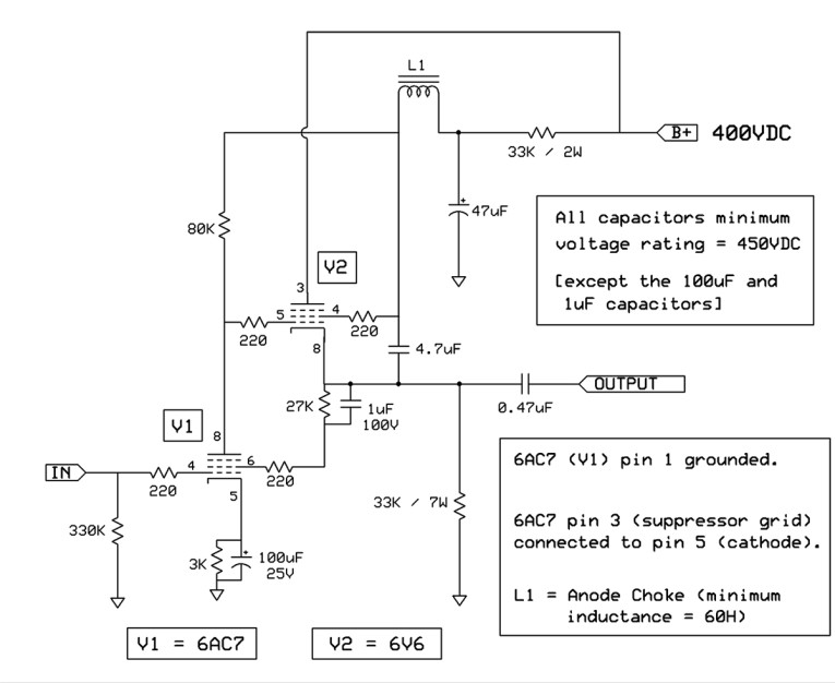
[As of 3/20/24, this post is still a draft in work. I'll update this first post with additional "lessons learned" over the course of a few days. -birdbox]

Somehow I found myself to be blessed to reach out to the right person at the right time (just after Christmas) and was given the gift to be an early builder of the Firstwatt Aleph J, Zen Mod edition. @ItsAllInMyHead was looking for some lucky folks to build the kits he’s working on for the store. I think his goal was to get a couple folks to verify the kits are complete, provide feedback on the to be released build guide, and share lessons learned along the way.

After eagerly accepting Patrick’s offer, I soon had the kit in hand and began the process of “asking Patrick a thousand questions”. Man is this guy patient and kind! I wanted to build it as fast possible, however, I learned along the way that “slow is smooth, and smooth is fast”. The build guide is top notch and certainly is on par with the quality build guides 6L6 provides the diyaudio community. This is going to be a fantastic kit for “new-ish” folks like myself, who have built some store kits in the past with SMPS power supplies, and are now interested into wandering into the Firstwatt amp designs with linear power supplies.

Up until this point I had built a pair of mono Amp Camp Amp’s, a couple Korg B1s, an Amp Camp Preamp+, WHAMMY, ACA-Mini, and the Zenductor (at BAF ’23). So although I wasn’t a tadpole anymore, I was still pretty much a minnow in a giant ocean. It was attending BAF in October of 2023 that had me catch whatever "bug" it is we call diyaudio. Before that event I was diyaudio-curious, afterwards, I was diyaudio-obsessed. Antibiotics did nothing, antivirals did nothing, the only cure was more amps! So I started to research and read regularly about what are some next options I could jump on. Iron Pre sounded like a fun project, but the store was sold out. My thinking was F5 would be a good first build, then I bumped into ItsAllInMyHead via a post and PM, and the rest was fate.

Ok, enough backstory, that’s not all that interesting really. Let’s talk this wonderful amp kit...

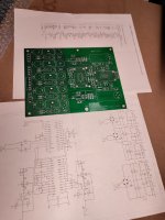
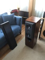
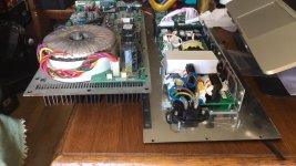
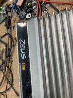
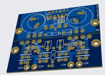
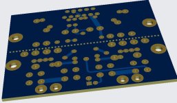
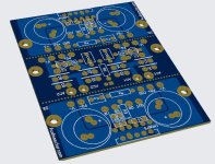
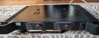
The boards are very well laid out, great fabrication with lots of shinny gold, and compact. They fit the universal mounting system (UMS), so I went with the chassis I had on hand from Modushop’s Black Friday sale, a 4U Deluxe. The kit provided had all the parts necessary to stuff the boards. I had already started to acquire some basic parts I knew I would need regardless of what Firstwatt design I’d try and build, so I had an Antek AS-3218 on hand as well as a AS-4220.

I also needed:
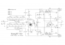
  • PSU Filter Board V3 from the store
  • Rectifiers – Monolithic using rhthatchers boards
  • CL60 Inrush limiter – using rhthatcher boards
  • Wiring
    • For AC & DC power & speaker out I used 16Ga – BNTECHGO Silicone Kits on Amazon
    • For signal I used Mogami W2330 from Markertek
  • Back connectors (Neutrik RCA & Speaker Terminals) – Back Parts Kit from store
  • Keratherm Insulator Pads – diyaudio store
  • Heat shrink – Amazon cheap variety kit
  • Crimpers – Haisstronica Crimping Kit on Amazon
  • Faston spade connectors (sorry ZM) – Mouser/Digikey
  • Power Entry Module – Back Parts Kit from store
  • M3 bolts - variety kit from Amazon
  • Standoffs - nylon spacers & brass hex variety kits from Amazon
  • ??
I did my very best to practice patience and go slow to ensure I did it right the first time. That wasn't easy, but I kept telling myself "Follow the process". I followed the build guide and asked Patrick lots of questions allong the way that he graciously answered with enthusiasm.

So, enough with all the words….time for some pics.

Here's 
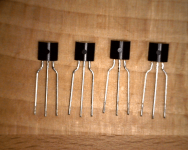
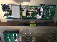
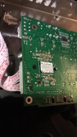
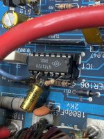
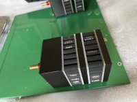
@rhthatcher 's insrush and rectifier boards all populated with components.
20240117_191335.jpg


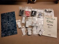
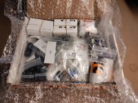
All the parts in the kit (I wasn't supposed to open it all at once, so don't do what I did)
20240120_194617.jpg


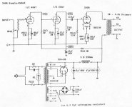
Crossing off components as they are installed on the schematic.
20240122_180549.jpg


Crossing off components as they are installed on the PCB layout.
20240122_180557.jpg


I loved the "verify" / "install" / "inspected" approach. This sets the stage for a really good quality process.
20240122_180603.jpg


Patrick shared the value and "tricks" he had for cleaning the board (99% Isop, Acid Brush, Kimwipes). I went one step further and got a cheap sonic toothbrush.
20240123_190624.jpg


I cleaned up the top and bottome with 99% Isop and sonic toothbrush. I would "rinse" the board with Isop after a scrub, then repeated 2 more times. 3rd Times a Charm.
20240123_191220.jpg


Oooooo, shiny!
20240123_191252.jpg


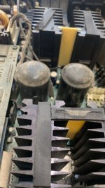
Extra large fender washer (1/8" ID x 3/4" OD), lock washer, and M3 boltholds MOSFET on Keratherm pad.
20240125_203919.jpg

Finished board mounted and torqued to 0.9 N-m.
20240125_203934.jpg


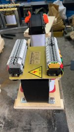
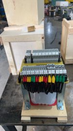
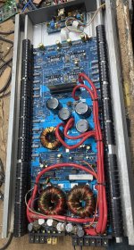
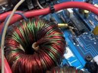
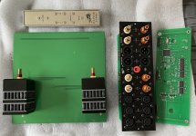
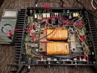
Laying out the linear power supply components.
20240129_123558.jpg


Twisted all the wires and mounted the AS-3218 on a fancy little seat so I could use "lip up" on chassis plate and still have transformer really close to front panel.
20240129_123713.jpg


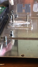
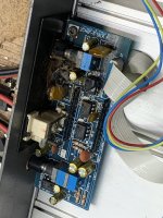
For space reasons, I used the Modushop "riser" to go vertical with the PSU filter board.
20240129_124043.jpg


Power supply checkout. Don't forget to wait plenty of time for caps to discharge. I would measure voltage with multimeter to be sure they were discharged.
20240129_202259.jpg


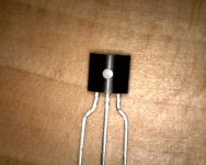
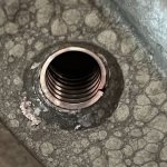
Don't forget the chassis thermister. I did at first. I slide it into the soft silicone insulation and use a little solder to secure it in place.
20240201_180252.jpg


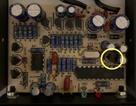
@rhthatcher rectifier boards with snubber resistors & capacitors per Quasimodo link suggestions. You'll notice the R values are different here than the picture above. Well, I ran into a really bad transformer hum issue. I tried every possible solution. It took me 3 days to figure it out. In the end, the problem was my recessed LED dimmable lights on a triac autodimmer. If the lights were set at 40-60%, transformer hummed crazy loud. Any other setting on the dimmer, dead silent. [Insert "The Far Side - We should write that down somewhere" comic.]
20240202_132040.jpg


Setting the bias connections using the little "grabbers".
20240202_132057.jpg


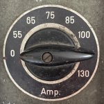
Bias setting heat soak. [0.46V across 0.27ohm yeilds a bias of 1.7amps]
20240131_183602.jpg


Trying to clean up the wiring with zipties after getting the DC offset down to pretty much 0.0V
20240208_183854.jpg


So how does it sound? I’m not very good at describing the “sound” of an amp with eloquent descriptions, personifications, and analogies, so I’ll just quote what I told Patrick after spending a few hours listening to it….

“WOW, just WOW”


By far the best sounding amplifier I own and punches well above anything I could have expected. This amp is not just a winner, it dominates. I love it. I’ll probably name it and keep it close to me for the rest of my life as my “first Firstwatt". What a wonderful experience.


Thank you Papa!

Thank you Zen Mod!!

Thank you so much Patrick!!!


Now, what's next?

Rosso-6MW150D sealed enclosure size

Hey just wondering what would be a good sealed enclosure size for the Rosso-6MW150D crossover is 500hz - to around 3khz might use stuffing might not use it I have 34l of sealed space in my 3 way towers just for the tweeter and midrange separate enclosure I want to divide up the space so it’s enough but not too big or small for the midrange speaker can anyone help please

Thank you

Urei 6150

Here is a Urei 6150. Another low feedback, wide open loop design. Leach inspired?. This has a bit of buzz on both channels through headphones or speakers. I believe its the layout design that causes this. All components test fine. Filter capacitors are also fine.

Buzz might be caused by this..

-There is some EMC shielding around the transformer but transformer will radiate still.
- Input shielded cables run very close next to mains wire input.

Apart from tthe buzz it actually sounds quite good. THD average..0.02% across full audio range. Bass full bodied.

Attachments

  • 20230819_205436.jpg
    20230819_205436.jpg
    401.3 KB · Views: 93
  • 20230819_101700.jpg
    20230819_101700.jpg
    168.9 KB · Views: 99

high gain contact mic preamp

Hi all.
Could you please give me some guide line for making a preamp with variable gain (60db or if possible 100db) with relatively accessible parts?
I was able to achieve a fixed 60db preamp with simple parts and dual 12v supply (with +-12v) and inspired with this project. sorry if it seems noob.


Screenshot from 2024-04-05 11-20-31.png


Now the problem is i now have a single 5v supply instead of dual ±12v.

Martin Logan 2nd / 1st gen CLS harmonic distortion?

It's been shown in several measurements by different people that Quad ESL63 can have very low distortion. Final ESLs have a reputation of having poor harmonic distortion either because they use an unusual drive configuration (inverted electrostat) or because they used to use high conductivity membranes. The example of a more recent Final ESL I found a review of pretty good, though:

https://www.diyaudio.com/community/threads/inverted-electrostat-inferior-in-distortion.409322/
Just one picture (ignore the 0.5% THD which is probably THD+N, the important thing is that the HD2 is 60 dB down = 0.1% HD2)
1712931994877.png


I also had a chance to measure an Acoustat 1+1 recently. I just did a quick test at 200 Hz at rougly 85 dB / 1 m and got HD2 about 55 dB down, so not bad at all.

There were also measurements of pre-production Capaciti panels in Klang+Ton and HobbyHifi magazines which were in the 50 dB+ range.

Well, I came across this review of the purity which has a Gen 2 CSL panel (same reviewer & magazine as the Final review, but different equipment and parameters):

https://hometheaterhifi.com/reviews/speaker/floor-standing/a-secrets-speaker-review15/

1 kHz distortion at (guessing from full FR sweep further down in the articla 87 dB / 1m ) is poor at 1.36%, this time stated as THD+N. More importantly, the HD2 is only about 37 dB down.

1712931726340.png

https://hometheaterhifi.com/wp-content/uploads/2015/08/martin-logan-purity-speakers-1-khz-large.gif

That number, however, is not consistent with THD+N sweep which should be higher because of the noise included and reads more like 0.6% at 1 kHz:
1712931657296.png

Even at 10 kHz, still 0.24% which is high for an ESL
1712931780512.png

Even the integrated ICE-T amp can't be that bad. So is anyone aware of reviews or other published measurements of Martin Logan ESLs? Is there a chance the Gen. 2 with their metallic coating and clear plexiglass spacers / dampers perform worse than the Gen. 1 with graphite coating, heavier foil and foam dampers?

LM1876 mute pin delay circuit in LTSpice

Hi all,

I am currently working on implementing LM1876 based amp and ran into the issue with the mute and standby pins.

From the datasheet, if a logic high (1.5 to 5V) is applied to the MUTE pin, the amp will be muted.

The goal is to mute the amp during the turn on (and turn off).
For that a logic high needs to be applied to the MUTE pin when amp is turned on, but after 1 or 2 seconds wait time the MUTE pin should be pulled low (< 1.5V).

I have come up with a simple simulation circuit that consists of :
  • 5V zener regulator
  • RC time delay
  • NOT logic gate

Power is taken from the positive rail of the amp's power supply that is 20V to 25V.

Zener regulator resistor is selected at 1K, and it pulls about 20mA of current.

Any suggestions on improvement will be appreciated.

Attachments

  • sch-mute.PNG
    sch-mute.PNG
    15.4 KB · Views: 212
  • responce_at_mute_pin.PNG
    responce_at_mute_pin.PNG
    15.3 KB · Views: 190
  • time_delayed_NOT.asc
    time_delayed_NOT.asc
    1.9 KB · Views: 102
Projects by fanatics, for fanatics
Get answers and advice for everyone wanting to learn the art of audio.
Join the Community
507,679
Members
7,883,946
Messages

Filter

Forum Statistics

Threads
406,016
Messages
7,883,946
Members
507,679
Latest member
tuan251