Huge wow on diy turntable

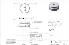
After 10-ish years in planning and working I (with help of my friend machinist) built my TT. It looks good but does not work good. When it turns, both 33 and 45 PRP, it is running unstable - wow is between 1% and 3%.

Here are what I have so far:
  • TT bearing is made of aluminum
  • Spindle is made of aluminum, with sintered bronze "sleeve" and it is sitting on steel ball at the bottom of the bearing
  • Both base and platter are made of several layers of "butcher block" wood and aluminum parts (yes, they are heavy)
  • Motor is Maxon A-max 110191
  • Mark Kelly speed controller sets speed
  • 3-IN-ONE oil is lubricating
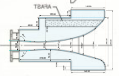
  • I am using a Chemical-Resistant Round Belt, 2 mm Diameter belt from McMaster-Carr.

PLEASE can you point me to what is wrong, how to improve it and make it finally work.

Attachments

  • Spindle.JPG
    Spindle.JPG
    36.6 KB · Views: 171
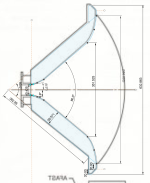
  • Bearing.JPG
    Bearing.JPG
    29.2 KB · Views: 161
  • Pulley.JPG
    Pulley.JPG
    85.7 KB · Views: 163

Need Help in troubleshooting Fluke 407D Tube power supply

I posted this last week in the power supply forum but did not get any input. It seems most of the post there relating to the solid power supply. Perhaps I have posted in the wrong forum!

I got this power supply advertised as power up condition only and currently tried to restore it. Replaced some components, weak tubes and checked most of them too. In general most of the components are still within the tolerance. Some exceeded slightly but I don't think it will cause much of the problem and did not replace them. Did not replace any Bumblebee caps since they're still within the tolerance (using LCR meter).

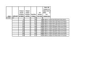
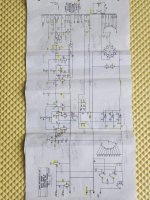
Attached is the output data after power it up. The main issue is it did not reach the max voltage except as noted in my file. Checked all resistors in the sampling network. They are fine. Negative 250V Bias is fine. I also checked out all parameters per Figure 4-2- Tube Voltage Chart on page 4-3 of the Maintenance section. The voltages are not really matched what specified there and don't know and not sure if they are really related to the issue that I have. One thing that's quite different from what specified in the chart is the pin 9 of V14 (6AU8). The chart said -61V on pin 9. It's measured about -61 voltage when Output Switch Position (0-500V) is in the "0" position only and I don't believe it's correct in other positions. My measurement on pin 9 started to turn to positive voltage when Output Switch Position (0-500V) dialed to position 100 to 500. On "500" position it measured about positive 289V. May be it's a typo perhaps.

One thing I noted is that on the cold day the output voltage increases from 15 to 30 voltages on "300-500" position scale. Thermal run away in some components??

I plan to take the Amplifier board out and replace all the components there. But before I do that I want to run through this forum for idea and input.

Appreciated with the help. Thank you.

Attachments

  • Fluke 407D issue.jpg
    Fluke 407D issue.jpg
    193.2 KB · Views: 74
  • Schematic.jpg
    Schematic.jpg
    466.9 KB · Views: 77
  • fluke_407d_sm.pdf
    fluke_407d_sm.pdf
    4.9 MB · Views: 43

Please help me find this vendor!

Somewhere I came upon a webpage or facebook page or someplace. A guy was selling active crossover boards with adjustable delay for time alignment. It was very similar to the boards that are sold at ampslab, but they had some different offerings too. They looked to be of very high quality. This was not the kind of stuff sold on ebay from China. If anyone knows who this is, I would really appreciate knowing.
Thank you

For Sale Vintage British, and other European amplification tubes for sale

Hi everyone.

Just moved my workshop and arranged all tubes I own from the 60's and 70'.

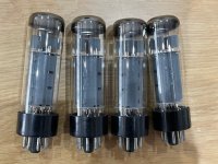
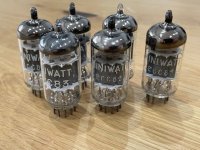
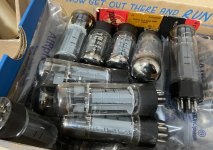
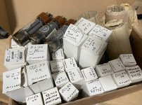
Found a large lot of ecc83, el34, el84, gz34 and other European amplifier tubes, multiple brands, that are used in vintage amps. They are mostly new and unused.

Would love to sell some to forum members replicating or restoring vintage European amplifiers of this era. I test all tubes for emission and transconductance and accurate measurements can be provided. I can select tubes for matched transconductance as well, if needed. For people with a tighter budget, there are some tubes that measure slightly used, which can be offered too.

Do not hesitate to message me if interested and I will check my stock for you, or recommend full sets for a given amp.

Payment via Paypal is preferred.

Shipping worldwide from Spain is very reasonable, tracked. Today I shipped 2 ecc83 , 2 el34 and a bunch of pihers and mustards, vintage pots etc to USA for 11,50 eur tracked, for instance. I usually offer free shipping for larger orders, however.

Prices vary between brands, construction, new or slightly used, print on tube etc, but here is an example of prices:

Ecc83 Philips Miniwatt made in Holland in the 60s, new unused. Ladder plates Halo getter. 60eur each

El34 RFT made in Germany in the 60s. Halo getter. 80 eur each. New unused.

I will post a couple example pictures asap of some tubes, so you can have a look.
Thank you,
Fran

Attachments

  • IMG_8812 (2).jpg
    IMG_8812 (2).jpg
    70.8 KB · Views: 134
  • IMG_8821.jpg
    IMG_8821.jpg
    72.4 KB · Views: 116
  • IMG_8838 (2).jpg
    IMG_8838 (2).jpg
    77.1 KB · Views: 126
  • IMG_7163 (2).jpeg
    IMG_7163 (2).jpeg
    475.7 KB · Views: 136
  • IMG_7161 (2).jpeg
    IMG_7161 (2).jpeg
    566.3 KB · Views: 134

Denon DRA-1025RA remote not working

I still have this receiver, recently the remote stopped working. Been using two TiVO remotes with it, and both stopped working with just the receiver at the same time (remotes still work fine with the TV and TiVO).

Testing so far-

I see data on the IR receiver, all the way to pin on 41 on IC901.
I see clock signal on pins 19/20.
VFD works fine, as are all of the mechanical buttons on the board, so I think the micro-controller is "alive".

Seems like there is not a whole lot that go wrong in this circuit, so I am looking for advice on what else I can test.

Link below to the datasheet for what I think is IC901.

TIA.


1744131162875.png


1744131136625.png


TMP47C670N

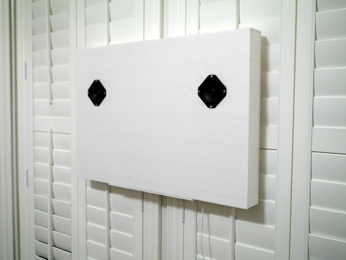
Ribbon Unity Horn

Though I love to tinker on car projects, I largely don't do home speakers because I'm really terrible at finishing things, and I'm really terrible at making speakers that look "presentable."

That's why I bought a pair of Gedlee Summas about ten years ago, and then replaced those with a set of Vandersteens when I moved to San Diego. (My wife banished the Summas to the garage, because our home was tiny.)

A month ago I managed to buy a house that's humongous, so I finally have an opportunity to put some horns back in the home theater. This project will be my attempt to do that.

GB for Hiraga Le Monstre 2024

We have quite some PMs asking for PCBs and kits.
Although we are not quite ready yet, we'll open a GB thread so as not to have to answer individually.
So this thread is for preliminary subscriptions.
We shall only confirm GB and call for payment when we are ready to ship.

First and foremost that we want to offer is a set of quad JFETs matched at operating point.
They are all GR grade, no Idss cherry picking.
Anyone can get them unmatched at eBay.
But matching yield is going to be low unless the matching pool is large (>100 pairs).
Or get matched complementary quads at a premium, if available.

JFETs alone would mean postage would cost an additional ~50%
So we offer our PCBs in addition, as there is little or no additional postage charge.
Again, the alternative is to use the Gerber we published of the original design.
Or get one of the many other designs being offered on the internet.

We want to offer a complete set of PCBs for building a pair of power amps.
For the power supply, we decided in the end against multiple LT3045 in parallel.
There are reports around that paralleling them is not without problems.
On top of that, they add 120USD easily to the overall cost, which we consider excessive.
If you believe the PSU to be critical, build the original with CRC and large caps.
Easier to do P2P wiring and no need for any PCBs.
For normal transformer based PSU, we settle on the LT3081, which is very simple to use.
And we shall test before offering (waiting for PCBs right now).
For best results, we shall use a 15V 1.5A pre-reg, such as L7815, to take out most of the 50Hz ripples.
We intend to use a 4700µF 25V Elcap upstream, and a 1µF MKS02 directly at the IC Pins, all direct P2P solder.
There are much larger caps at the input of the dual LT3081 PSU board.

We always use speaker protection.
The Improved PMA Protection circuit used in the F5Pi is unfortunately not suitable for +/-12V rails.
We already successfully tested a new circuit (XEN SSP3) designed specifically for the purpose.

So the entire standard package will include :
1x matched quad 2SK170GR / 2SJ74GR
2x amplifier PCBs
2x Dual LT3081 PSU PCBs
2x XEN SSP3 PCBs
4x TO220 Rectifier PCBs

100€ incl. EU VAT, excl. Postage

Fran wants to make life easier for those with less experience / equipment.
So we offer a limited number of full Q-sets.

The full package will then include all the above, plus
1x matched quad KSA992 / KSC1845
1x matched quad SS8050 / SS8550 -- preferred for the drivers
1x matched quad TTC5200 / TTA1943
4x TO92 heatsinks for Q3,4 black anodised -- for the drivers

140€ incl. EU VAT, excl. postage
Limited to 10 sets

Those interested please help us to keep a running list by updating yourselves.


Thank you for your interest,
Patrick
  • Like
Reactions: twitchie

Any drawbacks from Parallel Capacitors in Crossovers?

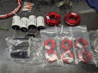
In a speaker crossover, is there any practical or sonic penalty that arises when two film capacitors are placed in parallel to achieve a required capacitance value?

I understand that in power supply decoupling there is concern. The effects of parallel values have to be the measured to verify the resonance of the capacitors (at RF frequencies) does not raise the impedance. It’s unclear if this has any real world effect in a speaker crossover at audio frequencies.

  • Locked
AD811 IV completed and tested

Sold Now
Working AD811 IV board, more details can be found here:
https://www.diyaudio.com/community/...s-input-nos-r-2r.354078/page-368#post-7451599
https://www.diyaudio.com/community/...including-burson-audio-op-amps-as-i-v.394295/

Pictures showing two boards,
MELF resistors version : configured for DAC with Iout +/-1mA eg. AD1862, PCM1702, PCM58 etc
1206 resistors version : configured for DAC with Iout +/-2mA eg. PCM63, tda1541 etc

NOTE : I am only selling one of the boards. I am keeping one for myself. All spare empty boards have been given out to some members here at no costs.
I will have to remove the aluminium baseplate which acts as heatsink due to shipping weight, which equates to costs.

Asking for costs of parts + shipping (registered + tracking) + a little more for my time/effort (just a couple of Starbucks latte) = 155 USD
Paypal FF only please.

The ultimate non-audio build thread

Or, what I’ll be working on instead of PA speakers and amps over the next couple years.

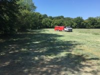
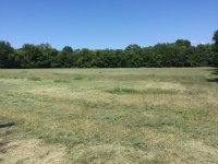
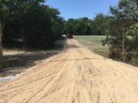
And so it begins - groundbreaking was this week. I can now drive the site without ending up on the ditch and needing a tow truck. When they cut the hay out there this week they actually left my stakes. I thought I was going to have to mow around the building pads this morning.

Contract for the metal buildings is in the final stage. The temporary mobile home is supposed to go in on the 27th.

Attachments

  • FF5C84B2-3EAF-447E-81FF-E8A92EBF2632.jpeg
    FF5C84B2-3EAF-447E-81FF-E8A92EBF2632.jpeg
    100.5 KB · Views: 310
  • 403023A9-42A1-42DB-907B-0D31532A4DEF.jpeg
    403023A9-42A1-42DB-907B-0D31532A4DEF.jpeg
    98.6 KB · Views: 310
  • F18BDA39-8B69-4F2E-9900-5E7C18C4464F.jpeg
    F18BDA39-8B69-4F2E-9900-5E7C18C4464F.jpeg
    104 KB · Views: 299
  • F458ACC0-FC6A-470B-A255-4A10786172EF.jpeg
    F458ACC0-FC6A-470B-A255-4A10786172EF.jpeg
    107.9 KB · Views: 313

Hypex NC502MP Case & Wiring

I have a Hypex NC502MP module on its way to me. I was going to buy the Ghent package to complete the amp, but since I’m in the US with the current tariff situation that is not an option.

Was hoping there may be recommendations for an amp case and wiring sources that may not be subject to the China tariffs? I’m not expecting a kit like Ghent, but this is a bit outside my wheelhouse and I’m not sure where to source the various wiring connectors I’ll need and the best options for affordable cases

TWQT / Hornresp help needed

Hello! 😃

I have a question about (folded) Voigt pipe speakers. (TQWT)

I’m thinking of making such a folded Voigt pipe speaker and I have seen some YT video’s of how a voigt pipe speaker(cabinet) works, but not in great detail.
It doesn't look/seems to look very difficult yet.
The difficulties for now are ‘putting everything into Hornresp.

I have two questions about that.

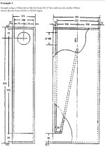
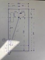
1: I have a drawing of the cabinet I want to base my speaker cabinet on, and there is a drawing (not to scale) I made with some S-L values in Hornresp.

But it’s a bit unclear to me what surface area and what length exactly what I have to fill in to Hornresp? I see some differences in what I have found on the internet.

2: I want to places full range driver and I want to know/see the full frequency response of the speaker when it’s finished.

Can I simulate that in Hornresp? If yes: How?


Hope someone here can help me a little further with this project.


Thanks in advance! 🙏🏻

Attachments

  • IMG_7363.jpeg
    IMG_7363.jpeg
    377.3 KB · Views: 161
  • IMG_7446.jpeg
    IMG_7446.jpeg
    273.1 KB · Views: 138

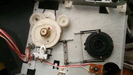
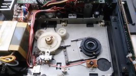
Bang&Olufsen Beogram CD50 repair and restoration

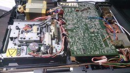
Latest precious vintage CD player that I managed to get my fingers on (for a reasonable price, seller stated it wouldn't open tray, no more info): Bang&Olufsen Beogram CD50. Hadn't had the chance to touch any B&O stuff yet, great experience, nice design and really, really solidly crafted, hadn't seen anything similar before. The player arrived very well packaged and in very good cosmetic condition.
The problem quickly turned out to be much worse than just a broken belt (as I had hoped).

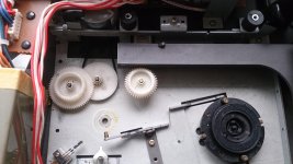
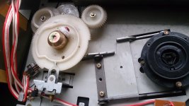
Upon opening (and downloading service manual), I quickly notice that the big cam wheel that is in charge of directing the movement of the tray (and the disc clamp), was completely off it's pinion, I mean it was just hanging in there in the middle of the other gears! 😱

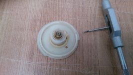
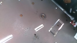
Turns out that someone before, in a desperate repair attempt, had broken the shaft loose off the base (of the metal framing), the pictures clearly show the damage. Probably because they didn't manage to get the brass holder off the top of the shaft, to be able to remove the gear and lubricate it. I wasn't able to get the brass thing off, either. Don't know why. Doesn't matter, as it was broke, so I thought a bit about it and quickly had an idea: I'd drill a hole into the shaft from the bottom, then cut a M2 thread into it (had some nice thread cutting bits and the appropriate hand tool lying around from the time I built an amp with custom metal case), and then fix the shaft with a screw to the metal frame.
My plan worked perfectly, wasn't even really difficult, and the gear was back in, sturdily fixed. One tiny problem (which later turned out to be important and I had to find a fix): the brass holder somehow was much too high, allowing the cam wheel do displace itself a couple of millimeters towards the top, so that the movement of the disc clamp would be different than intended. I later found a solution for that, as the last images show (a distance piece fixed by one of the holding screws which keeps the gear at the right position).

So, now that the mechanism was working modestly (obviously I took out all the old grease and lubricated everyhting, gears turning smoothly afterwards), but still stalling sometimes, I decided to try and see if the player would play CDs. After I got it to (supposedly) clamp the CD right, it started to try to play, but the motor would not move enough, the laser was trying to read (making noises), and the player then would stop and eject the disc.

So I figured laser was fine but tracking/focussing problems, whatever. Started with a good clean of the lens and measuring some signals. First, the power supplies. This was a problem as it took some time for me to understand that 90% of the circuits of the player would only get power when the main microprocessor would decide so. Then I learned that from the schematics and the power supplies (when turned on by the controllers), turned out fine. I then measured the focus signal - gave OK. Took out my oscilloscope and had a look at the eye pattern - looked nice, laser was great. What could be the problem? Decided to go through all the adjustments from the service manual. Took me hours. Last adjustments (which need a tone generator) didn't go well, I'm not sure if I misaligned some of the pots in the process, as it wasn't working like in service manual, although me following it all precisely. But basically I can say everything was perfectly adjusted (I had feared that someone might have "turned around a few pots", as the gear was broken and the player definitely had been in a tried service session or two, as the screws clearly were telling me....). But no, adjustment was fine. I managed to make it recognize a disc for two times and even play a few seconds, btw, by giving the disc motor a little kick start at the right moment. That left me thinking and I ended up measuring disc motor transistors and signal and turning the gain pot, with no success. Ended up calling it a night. But I was pretty sure the problem was somehow related to the motor.

Next day researched on the internet and found a great thread on beoworld forums, kindly the user Soren had made a nice tutorial to how to clean and lubricate the disc motor https://forum.beoworld.org/forums/t/628.aspx . I decided to test if this would really be a mechanical problem and applied quite a bit of silicone lubricant to the disc motor, letting it get into it. Then tried and woha!! the player started playing the disc!!! I heard music! So I was sure the problem was the disc motor being dirty and full of old grease, not getting right RPM at start so the controller would abort.

Decided to follow Soren's guide. But there was a problem: I couldn't get a 1,3mm Allen key easily. Ended up buying a nice kit of precision bit tools, really cheap and nice, which contained the 1,3mm Allen bit. BUT: it's a bit, so it's not that fine. Which means: as the space between that tiny screw which secures the disc clamp to the motor shaft and the metal frame is really tight, with that Allen bit, the platter hight adjustment would always be limited to the width of the Allen bit. Does that make sense? I had recorded obviously the originally set distance . Was about 5,2 mm, much more than in service manual. The bit allowed that, was about the minimum distance possible. So, I did all the process, motor was indeed full of dirt and old grease, was quite difficult to get off the brass ring, managed with two flat screw drivers at each side between the bell case and the screws of the PCB (so to not damage the PCB), this made the ring come off slowly, this indeed is difficult, but can be done.
Long story made short: disc motor was well cleaned and put together again, now turning really lightly, much better than before.

Put everything together and tried and.... bucket of ice cold water: the laser wasn't focussing anymore, no Focus OK signal, laser making noises, disc motor not turning, disc ending up ejected again! Why?? Started investigating, thinking maybe I tinkered too much with disc motor adjust pot yesterday and now that it's clean, doesn't work anymore, but now. Then by luck I discovered that the disc wasn't clamped correctly!!!
I clamped it and.... player played the disc nicely!!! 😀
So, I now knew the problem was the platter hight adjusment. But I did adjust to the same hight as before??? Could this have been tinkered with, in another desperate attempt, after breaking the pinion of the cam wheel?? In fact the screws showed signs of having been turned and the 5,2 mm distance was strange. So, I ended up grinding the little Allen bit so to make it thinner in order to be able to adjust a smaller distance... very bad when one can't get the right tool. But my dad learned to make tools when he was a teenager after WWII, so I guess it's in the genes ahaha... Now that I had a working tool, I adjusted the distance. The problem: couldn't get it well, and then I discovered why: the cam wheel of the loading mechanism had too much play, as already reported above, due to brass holder being to high. So I improvised a spacer. Done! Now, I could adjust the platter hight. Took some trial and error, as it easily gets too short as well. Ended up nailing it, around 4,9 mm, just like service manual, disc well clamped and spinning perfectly!
Tried it out and YES!! Player is now reading perfectly all kind of CDs, even CD-R and badly scratched ones, quick initial reading, good track changes, plays until the end of the CD, every time, hasn't failed once! Disc loading mechanism also improved with the spacer, hasn't stalled anymore, although a little slow still. But as I'm going to exchange the electrolytic caps, maybe it will get better if voltages get better filtering and more stable? If not, let's see, maybe the belt is worn (haven't changed it as it looks fine and seems to work).

So, now I'm ready for exchanging caps and the rest of the service.

I do have a question and would like to hear opinions: shall I go again through all these (really daunting) adjustment steps according to service manual after recapping? As I possibly messed up a couple of adjusments yesterday when the player wasn't working well and that tone generator adjustment thing didn't go well or should I simply leave it alone if it continues to play as nicely as now, after changing the caps??

As I'm not sure if I can do these last adjustment steps which envolve the tone generator...

Two more things: I noticed this player uses PCM53 which is a mono DAC and is mutiplexed by switching at high frequency between left and right to obtain stereo. This, from point of view of audiphile, isn't nice at all, but the DAC still seems to sound nice (have read a lot on the net), and there doesn't seem to exist an alternative (except for using two chips, which I don't have), but I thought: maybe I can get a better multiplexer chip than 4053?? So I ordered DG303. Also OPA2134 as replacement opamps for output filters. Does anyone have some advice about implementation of these new and better pieces of silicone into the player? 😎 I think I'll figure it out, but if anyone has done this before...

Will let you know how it goes.

Attachments

  • DSC_2289.jpg
    DSC_2289.jpg
    1,001.9 KB · Views: 527
  • DSC_2290.jpg
    DSC_2290.jpg
    994.5 KB · Views: 436
  • DSC_2291.jpg
    DSC_2291.jpg
    786.5 KB · Views: 405
  • DSC_2296.jpg
    DSC_2296.jpg
    642.7 KB · Views: 433
  • DSC_2298.jpg
    DSC_2298.jpg
    799.1 KB · Views: 526
  • DSC_2299.jpg
    DSC_2299.jpg
    708.3 KB · Views: 406
  • DSC_2302.jpg
    DSC_2302.jpg
    708.6 KB · Views: 445

Idle current adjustment and temperature help

Greetings to all!

I have a Denon integrated and I noticed on idle or full steam one of the power amplifier heatsinks is noticeably warmer than the other. So I begin by disconnecting all of the wires from the amp, volume to 0, cd as an input and tone defeat ON. Let it cool down for 4h and check the idle current after 10min mark at ON(the amplifier has only this adjustment pot). Left one was a little lower (11mV) but the right one was a little higher (13.5mV). It was very hard to adjust the left one. It drifts too quickly and it's not so stable. So I've only tinkered with that side for now and managed to set it up to 12mV. So I've decided to leave the right one untouched. That way after 60min on time it balanced out to stable L-11.6mV/R-11.5mV. The thing is that now after some testing the right heatsink still heats up more.

So I have a couple of questions on the subject which I'm not sure I understand correctly:

1. Is it normal for the idle current to drift a little constantly (+/-0.1)?

2. The manual states " setup after 2min ON time to 12mV, and after 10min to 12mV ''. So I don't have to bother afterwards if it fluctuates outside 12mV? Or I have to measure again after lets say 60 min ON time? I came to notice that the current stabilizes after about 45min+......

3. Do I have to set up the L and R side to be at 12mV on the 10 min mark or after 60min?

4. The tolerance for setting up is 0.5mV. If I get it set up to L - 11.5mV and R - 12.5mV is that good?


Any advice will be appreciated!

Doubling the capacitance of input coupling cap.

I am rebuilding a Marantz 2270 and I am currently working on the amplifier driver boards. There is an input coupling cap (C751) which is a 1 uF polyester film I believe.

IMG_6439.jpeg


I am wanting to put something on the nicer side in that position. I have some fairly nice polycarbonate caps and have read that they are highly regarded. Any negatives to going to this 2 uF cap? I also have some nice 1.7 uF polypropylene. I also have some nicer ones that are a little bit bigger, like 3.3. Though I’m leaning towards the polycarbonate. How big would you potentially go in this position?

Dan

Growing interest in analogue electronics!

Hello! Im a Swedish guy in my late 20's and have a growing interest in fault search, repairing and learning about analogue electronics as Amplifiers.
Started a account here to learn from people whit common interest!

Im pretty new but know a bit of the basics of analogue electronics but wish do get a deeper understanding.

Have a nice evening!
  • Like
Reactions: gabdx and freon2

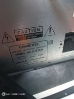
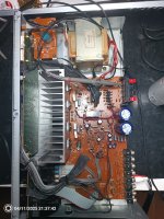
Onkyo A-8150 (from 1990~), A cracking noice at 50-100hz from the speaker.

Hi everyone!
I have a renovation Project going on on my Onkyo 8150 linear PSU from around 1990+.
This cracking noise comes whit heavy bas around 50-100hz
The speakers i use is KEF 103/3.
These speaker works fine on my NAD 310.
Now im pretty new att fault searching analog tech.

Ive look through the basics:
-look for burned components
-try solder joints
  • Thermal camera to see if specific components goes to hot compared to the data sheets.
  • check for suspicious caps

All i can see is that the PCB have been a bit hot at the driver transistors.
Someone before me have soldered a 0.56pF cemaric kapacitor between the Emitter and Base probably because of this problem (same transistor that have heat development at the PCB.
I wish to know why 🙂

A Newbie like me are Thankful for all input and advice🙂

If you need more pictures ill post them.
Even got the schematic for the amplifier

Attachments

  • IMG_20250411_213751_539~2.jpg
    IMG_20250411_213751_539~2.jpg
    532.3 KB · Views: 19
  • IMG_20250411_213804_030.jpg
    IMG_20250411_213804_030.jpg
    254.5 KB · Views: 16
  • IMG_20250411_213743_130.jpg
    IMG_20250411_213743_130.jpg
    662 KB · Views: 14

Optimal replacement 8" drivers for M&K MX700 subwoofer

Replacement woofers for MX700 subwoofer

I have 3 of them and I'm thinking of experimenting on 1 of them since the plate amp is malfunctioning.

Currently using a Crown xls2502 configured in bridge mono and 85hz low pass to replace the plate amp. Cut the + and - and pig tied them to some speaker wire and connected the amp. Works.

Now I'm thinking what would be the highest performance 8" speaker driver to replace the existing M&K 8" drivers? How to I select the drivers based on the push pull configuration?

I'm looking for very fast and clean bass down to 20ish hz. They would need to run without too much heat as I often listen for hours at a time, albeit not at super high db levels.

I have a few Crown and other pro amps lying around and really like the form factor of the MX700 so when those plate amps die, I have a solution.
Thoughts?
Thanks in advance.

For Sale Apex FH9 class AB mono blocks

This is a pair of Apex XRK Audio modified FH9 boards, Dual mono blocks that run in AB
50 watts 8 ohms they are dead quiet and sound fantastic
The amp uses 2 of the Prasi CRC power supply units,
Includes both boards mounted to the heatsink 2 Antek 300va 25v Transformers
2 separate Prasi PSU CRC Boards
Which can also be used for Class A amp boards as well.
So you could mount them to a board as I show here
Or throw them in a nice enclosure and you have a fantastic sounding amp ready to go.
Asking $600

Attachments

  • IMG_4265.jpg
    IMG_4265.jpg
    706 KB · Views: 346
  • IMG_4274.jpg
    IMG_4274.jpg
    583.6 KB · Views: 349
  • IMG_4270.jpg
    IMG_4270.jpg
    647.9 KB · Views: 358

Interested in a portable Version of Leap 4?

I believe I figured out a method that allows Leap 4 to work on any windows machine via a free DOS emulator with no key required. I wanted to see if anybody was interested in obtaining a copy of this. I'm not a computer expert, I do know enough to get into trouble. I'm still working on making this portable but I am able, at this time to use leap 4.6 on my Windows 11 computer with no apparent issues. I have used leap as a hobbyist and professional for 30 years and can say that this is one of the most important pieces of software ever written for the loudspeaker industry although being a 1995 DOS program, it is still a rich and powerful program to use for loudspeaker design and is as relevant today as it was 30 years ago. I also own Leap 5 but I can say that Leap 4 has a special place in my heart. I understand that I'm talking about software as it was an old girlfriend or something but I have designed hundreds of systems using leap and it is as brilliant piece of software and it's so unfortunate that Chris Stram died at such an early age, he was a brilliant engineer and software developer. Please let me know if interested.

Geoffrey
  • Like
Reactions: head_unit

Naim NA 323 clone from Aliexpress - gain, input configuration

Hi
out of curiousity i bought two "Mofi 323 DIY kit's" to assemble a symetrical input to output phonostage.
The result is so far not bad, but output levels seem very low compared to other MC Phono Stages i use. I needed 7-9db more gain to be on similar levels. (atm. AT OC9 for testing)

Some investigation brought up that - in the original diagram from Naim - R13 220R can be reduced by half, lifting the gain +6dB
"Note that the gain can easily be adjusted (I've tried changing it by afactor 2 with no problem) by changing out R13 (220R). For example putting in a 110R in its place will double the gain,which may be useful if you are trying to match the subjective output from LP and line inputs" - Yes i want that, but:

Another person tried the opposite, decrease the gain, using a 470R resistor as R13, but he also changed C4 from 47uf to 22uf. This would indicate that in the increase +6db case, C4 should also be swapped to 100uf.

i then found an explanation, that C4, 47uf acts as rumble filter with the 220R in series and that increasing gain leads in higher (30Hz?) HP filter.

Now, lets say i wanted to reach 65dB of gain, and needed 10-12 db more, would 56R and 220uf be the right way, or is the circuit not designed to go that high?

How about input configuration for a DL103R - or even lower impedance MC like ZYX or certain Ortofon MC's?

original circuit:
Naim NA323.png

Naim 323 clone.JPG

Mofi clone circuit, here it's R58 & C19

thanks for hints. here is the PSU circuit:

NAIM 323 PSU.JPG


this circuit seems to produce more 100Hz Hum then my lab PSU...

thats it so far.

cheers!

Hello from British Columbia!

Hi everyone! glad to be here! I'm Dan. I've worked with electronics both as a hobbyist and professionally for about 25 years. I used to work in TV repair shops back when they were still around. I have no formal education in electronics, but have had a lot of help from elders and kind people along the way, as well as lots of self study and practical experience. That being said, i'm not perfect and sometimes need a push in the right direction (you can't know everything!) I'm very open to learning, and helping others if I can. I really enjoy helping others! I hope I can contribute and be helpful here, as well as learn and have some laughs. How's everyone doing today? what are you working on?

Let’s Talk About the Faital 12PR430 – Anyone Built It?

Hi everyone!

Currently working on a DIY project based on Troels’ Faital 12PR430 design. Has anyone here built it or something similar?
I’m running into a few issues with the components and would really appreciate some advice or tips from anyone with experience.
I previously built the DTQWT MKIII, which I ended up modifying quite a lot — some big changes, actually.
If you’re curious about that build or have any questions, I’m happy to share details!

Looking forward to hearing your thoughts and experiences.

L12-2 V 4.2 Sound Quality (too bright?)

I completed this amp today (L12-2 v 4.2) and left the whole amp untouched as bought. My thinking was that I'll do the "Mods" at a later date as I have room to easily remove the amp boards from the enclosure. My initial reaction was a disappointment to me. I have used the LJM L20 V9.2 boards with film input capacitor being the only mod. To me the L20 amp was pretty well perfect. Very neutral with no overall audio signature, just as if the input was driving the speakers with nothing in between (yes, I know it's impossible, just a sort of illusion) However the L12-2 is definitely brighter making all music styles just seem colder and unnatural. The bass is a little odd too.... seemingly less controlled and fatter. Yes, so far, a disappointment but the ads do carry a "Warning" saying the amp is bright!... There is a YouTube video showing a subtle rise in the frequency response. It seems very strange to have a non-flat frequency response in a modern amp, but I reckon this is enough to explain what I can hear, as it's over a wide upper response area. I would be VERY interested to hear what others think of their L12 amp used with highly neutral and detailed speaker. Thanks
Login to view embedded media

Experimenting with Multi Entry Horns

I have always been facinated by the Synergy/Unity/Multi Entry horns. I have read i think most of the threads here on DIY audio and elsewhere on the web including danleys patent and more... After the DFM groupbuy here on DIY I suddenly have three compression drivers in my hands.. So now I no longer had any excuse and have begun experimenting myself!
I also have quite a few of the small SB full rangers (SB65WBAC25-4) on hand. I have no idea how good these drivers will be as MEH mids, but we will se. I was kind of fantasysing about the Scanspeak 10F/4424G00 based on the 2*FS/QES formual they score 562 which to my understanding is pretty good?

The dream is to build three bigger 3-way horn for use as Left, Right and Center fronts in a future home cinema/listening room.

However, for now I just want to do some smaller scale tests with what I have to see if my understanding of the concept is correct as well as do some experimentation.

While I understand that the corner placement of taps in the horn reduces the taps impact on the HF performance I really would prefer an eliptical horn based on the ATH formulas from a visual standpoint. Therefore the first experiment will test if it is possible to get a decent HF performance from such a OSSE horn with taps in it.

So I started by designing a parametric horn that has replacable taps to quickly iterate differnt shapes and sizes of the taps. This is what it looks like with the midranges attached
MEH prototype front.png
MEH prototype front side.png


Horn samlet bagfra.jpg

Quick comparison -> OP-Amp Noise -> Simplified calculation

The recent disputes regarding the lowest-noise operational amplifier, mainly as a single-stage phono EQ, have prompted me to ask:
how can I get a concrete reference point as quickly as possible, comparing individual types of OP?

Whether absolute values are generated is irrelevant, it is the comparison that is of interest. The type with the highest SNR wins.


SCHEMATIC

1742553290502.png


The win32 program noise.exe opens a cmd and presents itself as follows:

OPu=
OPi=
G1k=
Rq=
Ltc=
Rdc=
R1=
R2=
R3=
df=
T=
1.730631e-007[V] 1.747937e-005[V] 88.53378[dB]
99.0099 7500 3112.292 10000 100 3333 47000

OPu=

C:\Windows\System32>


enter as a normal floating point variable or confirm with the enter key, the rest will become clear as you play.

  • OPu stands for en in V/sqrt(Hz) and OPi stands for In in A/sqrt(Hz) of the operational amplifier used
  • Rq stands for the resulting effective resistance of our pickup, alternatively a DC resistance (in ohms) and a coil inductance (in H) can be specified
  • df stands for the desired bandwidth of our thermal noise (in Hz)
  • T for the temperature (in °C) ...
If you assign a value to OPu after the first run, the input starts from the beginning (you can simply confirm (the stored default values) with the enter key).


#
Have fun with it - and of course I cannot guarantee correctness and correct operation.
However,
the theoretical calculation of the noise, manifested here in the SNR (last output value of the first line), is actually trivial.

Nevertheless,
I could have made a dozen mistakes.


HBt.

Attachments

  • Like
Reactions: Drone R2D2

Thanks for welcoming me to this forum!

My name is Pablo, I’m from Argentina, South America, and I’m an audio enthusiast with a deep love for high-quality sound reproduction.

Right now, I’m planning to build the Faital 12-430 speakers designed by Troels Gravesen. I already own a pair of DTQWT-mkIII, also designed by Troels (heavily modified, I must say), and they’ve given me countless hours of listening pleasure.
On the electronics side, my main setup consists of push-pull tube monoblocks with 6L6WGC tubes, and a preamp using RCA 6SN7WGTA tubes. I’m also working on another project: a KT120 push-pull tube amplifier, with diode rectification and fully point-to-point wiring.

Aside from all that, I’m also a bit of an IEM fan—love playing around with different DACs and digital sources to explore new ways of enjoying music.

Looking forward to exchanging ideas, learning from you all, and hopefully contributing to this amazing community of audio lovers!

Attachments

  • IMG_1037.jpeg
    IMG_1037.jpeg
    627.8 KB · Views: 19
  • IMG_3418.jpeg
    IMG_3418.jpeg
    727.2 KB · Views: 18
  • Like
Reactions: dantwomey

4-way instead of 3-way?

Hi experts,

I'd like to put my thought or plan or whatever to get experts' advices on it.

I have been thinking of a new 3-way speakers around the same ATC SCM75-150s, complemented with Scanspeak D2104 21mm tweeters and some 8" double woofer instead of a 10" Volt B2500.1.
Then I was invited by another DIYer for auditioning his new speakers using Raal 70-20 tweeters, Scanspeak's freakin' expensive 83mm dome midrange, also Scanspeak's illuminator 7" as a midbass, along with Scanspeak's 13" woofer. He originally planned a 3-way without the midbass, but got an advice from a professional to add the midbass in between. It sounded awesome, and also seem to prove the superiority of the 4-way design.

So, I began to wonder what if I add midbass between ATC and 8" double woofers. My logical half tells me professionals and experts will say midbass is not necessary with 8" double woofer below. But I am still curious. What are your thoughts about this?

Regards,
Jay

Quick question for anyone who has used the SB Acoustics ceramic woofers

I am considering using the 6" SB Acoustics ceramic woofer in the system thats going in the kitchen. The wife is questioning the ability to clean this cone. Valid considering we sautee food in there on a consistent basis.

What does it feel like? Is it smooth and easy to clean? Or is it sort of porous and the white might end up looking horrendous in a handful of years?
https://www.madisoundspeakerstore.c...coustics-sb17cac35-8-6-ceramic-woofer-8-ohms/
1744338767425.png

delay on the B+ or not

I have a question regarding my preamplifier external psu

We have 4 transformers 2 in each channel all power up with the same mains switch on the front unit. I have read the its not good for the tubes the b+ and the heaters power up at the same time. So because i dont want to mess up with delay boards and too complex soldering, can i put a second mains switch seperate from the heaters because i have the advantage of separate transformers for hv and lv and power on heaters first and after a couple of seconds the hv or leave it as it is now in the risk of starting a fire again?

I forgot to tell you that the second transformer at each channel is output 15v ac for the preamplifier heaters and then goes to diodes, caps and 7812 SPARKOS regulator for a steady 12v dc and 6.3 v ac connected directly unregulated to the ECL82 tube HEATERS.

Is it safe then if i go with the 2 mains switches to power up the heaters transformer first but the ecl82 will have the heaters on but no hv to regulate which is coming next after i power on the hv transformer?

Attachments

  • IMG_20250409_130105.jpg
    IMG_20250409_130105.jpg
    397.5 KB · Views: 50

6SL7/6BL7 driven Electra-Print 300B

Combed through the Electra-Print schematics and this caught my attention. I've been looking at it off and on for a few years and might move forward. I have a load of 6BL7 tubes so I don't care that they're obsolete. I have just as many 6BX7's that I could swap out. Power supply will need to be beefy. Other than that, it looks straight forward.

I love the simplicity and how hard it's being driven. Anyone ever heard of this being built?

Attachments

  • 300B_SE_6SL7_6BL7_3K.gif
    300B_SE_6SL7_6BL7_3K.gif
    13.1 KB · Views: 246

An F5 with laterals

I have an F5 with Toshiba laterals. I have the source on the power lines now; however, with my Maggie at 4Ω it is rather too harsh sounding. So back to some source degradation.
What do you think of the following development path? [I used to have such a version with the source resistors and it sounded good actually so after some years I am thinking of 'going back'.]

Scherm­afbeelding 2025-03-14 om 14.18.49.png

The difference with my 'standard F5 build' is the drain resistors and the fad of the 3Farad capacitor. In fact, that forces a nice harmonic degradation on paper.

Attachments

For Sale Complete Zen v4 Amp

For sale is a complete working Zen v4 amp.

I am using Jim’s Audio PCB boards. All of my speakers need a more powerful amp (and I built 2), so time for this project to have a new home. The case is pieced together 4U parts from this site’s store since I already had some previous 4U parts. The back is vinyl wrapped.

New lower price of $400 and now including a set of blank F4 boards, full set of IRFP transistors for it, the original blank Honey Badger boards and the negative side of the blank power supply boards in case you want to put something else in this case.

If you’re in the Detroit area you can hear it, otherwise I’ll ship it. If you’re committed to purchasing it, we can FaceTime as proof of operation.

$650 $400 plus shipping.

IMG_3360.jpeg

IMG_3336.jpeg

IMG_3315.jpeg

For Sale High end stereo amplifier, based on 3e 480-1-29A modules

I have for sale stereo amplifer, based on 3e audio mono 480-1-29A modules, precisely installed in custom build beautiful enclosure. I put a lot of effort to squeeze the best sonics from this modules, providing special SMPS with quality components and additional capacitor board (designed by myself) to further improve the sound.

Stereo amplifier consist of:

- 2x 3e 480-1-29A amplifier modules (latest version with OPA1656 opamp and Nichicon capacitors), bought at Audiophonics. More info here: https://www.audiosciencereview.com/...tpa3255-amplifier-kit-480-1-29a-review.50283/

- Microaudio SMPS 600R2 power supply (+46Vdc).

- additional capacitor board (per each channel). It consist of Nichicon FW 1000/470 uF and KZ 100 uF capacitors, bypassed with 1 uF Mundorf MCAP MKP capacitor

- aluminium enclosure specially made for this amplifier. Front and side plates are made from 10 mm aluminium (CNC machined). Other plates are made of 3 mm aluminium. Enclosure has extremely fine black power coated finish.


For wiring speaker lines, Jantzen solid core wire was used. For power supply wiring, Jantzen stranded wire was used. Dimensions of amplifier are: 28x34x9 cm (WxDxH). Amplifier is in perfect operating condition. Input is provided with high quality Neutrik XLR terminals. Weight of this amplifier is a little over 6 kg, so not big deal with shipping.


Price is 500 EUR + PayPal fee + post costs


NOTE: I am not responsible for any customs fees, taxes, import duties.

Attachments

  • chassis II.jpg
    chassis II.jpg
    621.3 KB · Views: 370
  • chassis III.jpg
    chassis III.jpg
    559.2 KB · Views: 370
  • chassis inside II.jpg
    chassis inside II.jpg
    303.8 KB · Views: 494
  • chassis inside III.jpg
    chassis inside III.jpg
    279 KB · Views: 500
  • back.jpg
    back.jpg
    762.8 KB · Views: 491

LJM amps or other sugestions for basic amp build

Hi, i would like to build a basic amplifier using readily available kits.
what i read about LJM kits vary a lot from one thread to another. Some say they are great kit and some other simply burn them.

i already have a psu with 42v rails at 500VA so this is my main starting point.
i would like to have at least a modest 50wrs into 8 ohm, more is welcome.
MX50X2 seems a good candidate.
MX50SE seems on the edge for 42v mains.

The amp will be used in a bi amped system, running the upper range (not bass).

any suggestions is welcome, links to trusted sellers too.
thanks.

Hello all

Απλώς να κάνετε όπως ζητάτε και να λέτε ένα γεια.

Αυτό είναι το πρώτο μου βήμα σε ένα φόρουμ και στα ηλεκτρονικά, γι' αυτό παρακαλώ να είστε ευγενικοί!
Το θετικό είναι ότι είμαι αρκετά πρακτικός έχω ένα καλό εργαστήριο και απολαμβάνω να μαθαίνω νέα πράγματα και να φτιάχνω πράγματα, ειδικά όταν είναι κάτι που δεν έχω ξανακάνει.
Εδώ και πολύ καιρό ήθελα να αναβαθμίσω το Hi-Fi μου και αυτό φαινόταν λογικό.

why does Planar response Rise and CD response fall ?

let's say you're looking for a driver to cover 1.5 khz to 10 khz with high efficiency.

you can use a Planar like the Radian LM8K with response like this:

1742243015426.png


or you can use a Compression Driver like RCF ND650 with response like this:

1742243139375.png


between the two of them the Planar slopes up by about 10 db and the Compression slopes down by almost 10 db

i have been trying to research why but the answers are not fully satisfactory.

the explanation for the CD is supposed to be "mass break point" but after extensive googling and reading this JBL paper:

https://jblpro.com/es/site_elements/tech-note-characteristics-of-high-frequency-compression-drivers

i was not able to find a single explanation anywhere on the internet of what exactly mass break point is and what causes it. the formula given by the JBL paper:

1742243642805.png


takes only motor force ( BL^2 / Re ) and diaphragm mass ( MMS ) as input and magically puts out 3.5 khz as output. it further blatantly states that no matter what driver you use it will always produce about 3.5 khz output because a larger driver will have twice the motor force and twice the diaphragm mass.

this formula is maybe the strangest i have ever seen. why would higher motor force result in higher bandwidth ? my theory is motor force here is simply a stand in for voice coil diameter because all compression drivers have approx 2.0T flux strength in the gap so motor force in real drivers will be proportional to VC diameter and of course MMS will also be proportional to driver size and JBL states in the same paper that Mass Break Point is always around 3.5 khz regardless of what driver you use so it seems the formula is simply designed to basically take driver size as both numerator and denominator in order to have everything cancel out and leave you with just 3.5 khz as result.

the paper further states that the space between diaphragm and phase plug ( about 0.5 mm in most drivers ) is not large enough to matter and is NOT the mechanism behind mass break point.

so what is the mechanism then ?

and it is equally mysterious why Planar response rises. most people intuitively understand that it has something to do with beaming because the power response of the planar is flat, only the on-axis response rises. but why isn't the same effect observed in an array of cone drivers ? why doesn't an array of cones exhibit a rising response ? why only planars and ribbons ?

i was able to come up with a theory that the reason for discrepancy is the low mass of the diaphragm. that is heavy cones are more efficient at lower frequencies where mutual coupling increases acoustical radiation impedance ... while ribbon / planar diaphragms work better with lower acoustical impedance at higher frequencies. this would account for the kind of response rise we see in ribbon tweeters, whereas in the Radian planar there is additional bump around 10 khz due to cavity resonances as well as membrane resonances so i could accept the planar response as being explained by a combination of these factors.

but i still don't understand mass breakpoint of compression drivers. why is it a thing. and what is it ?

i can only assume it has something to do with the phase plug because only drivers with phase plugs seem to exhibit this phenomenon. a 2.5" titanium dome like in RCF in questions should be able to go to 8 khz or so before breaking up yet it begins to roll off much earlier, even in on-axis response, and probably around 3.5 khz as JBL says when measured on plane wave tube / power response.

it must have something to do with the mass of air in the phase plug acting as a bandpass port. but, as i said, i was not able to find a single explanation anywhere online as to exactly what it is.

on a somewhat unrelated note i think it is noteworthy that at 10 khz both the planar and the compression driver are at about the same 105 db efficiency, while at 20 khz a true ribbon beats them both with over 100db efficiency. if radiation patterns could be matched a perfect speaker would use a true ribbon over 10 khz, a planar from about 3 khz to 10 khz and a compression from about 600 hz to 3 khz but nobody optimizes drivers for those frequency ranges and in practice both planars and CDs are designed for the same frequency range and you must pick one or the other, but for that you have to first understand both, which is what i am trying to do.

Seeking Guidance on Designing a 500W RMS Class D Amp and Learning Class TD for a Future 5kW Output with Low THD

Hi everyone,

I’m diving into Class D amplifier design and exploring Class TD (Tracking Class D) in parallel, and I’d really value the community’s insights to help me get started. My ultimate goal is to design a 3kW-4kW Class D amp at 4 ohms to power 21" and 18" outdoor speakers within the next two months. As a learning step, I’m focusing on building a 500W RMS Class D amp at 4 ohms. At the same time, I want to learn about Class TD to understand its benefits for high-efficiency, low-THD designs, aiming for a future 5kW output with minimal distortion for my outdoor audio setup.

My background: I’ve successfully built a 1000W RMS Class AB amp at 2 ohms, so I’m familiar with amplifier design, power supplies, and testing. I have a well-equipped workbench with an oscilloscope, load resistors, signal generators, and other tools. While I’m comfortable with Class AB, Class D and Class TD are new territory, and the switching concepts feel daunting. I’ve been searching online for resources, but I’m struggling to find clear, practical guidance on where to begin for both topologies.

Here’s what I’m looking for:

  1. Roadmap for a 500W RMS Class D Amp (4 ohms):
    • A step-by-step approach to design a 500W RMS Class D amp, covering key components like PWM modulators, MOSFETs, gate drivers, and output filters.
    • Reference designs or schematics for a 500W Class D amp that I can build and learn from. Are ICs like IRS2092 or IR2110 suitable for beginners?
    • Tips on output filter design to minimize Total Harmonic Distortion (THD) and ensure clean audio.
    • Recommendations for simulation tools (e.g., LTspice, Multisim) and how to model Class D switching circuits accurately.
  2. Learning Class TD in Parallel:
    • A beginner-friendly introduction to Class TD—how it differs from standard Class D, its advantages (e.g., efficiency, THD), and why it’s used in high-power audio.
    • Suggestions for resources (books, articles, videos, or tutorials) that explain Class TD design, focusing on practical steps for someone with Class AB experience.
    • Are there reference designs or ICs for Class TD amps I can study? How do Class TD designs adapt the power supply tracking to reduce losses?
    • Tips on how to start experimenting with Class TD concepts while working on my 500W Class D project—any small-scale circuits or simulations to try?
  3. Minimizing THD for Both Topologies:
    • Techniques to achieve low THD in Class D and Class TD designs, especially for scaling to 5kW. What impacts distortion most (e.g., feedback loops, filter design, MOSFET choice)?
    • How Class TD’s tracking power supply helps reduce THD compared to Class D—any design tips to leverage this?
    • Testing methods to measure and optimize THD using my oscilloscope and signal generator, particularly for high-power loads like 21" and 18" speakers.
  4. Learning Resources:
    • Recommendations for books, courses, or tutorials on Class D and Class TD design, ideally suited for someone transitioning from Class AB.
    • Resources that break down PWM, switching topologies, and tracking power supplies in a hands-on way.
  5. Transitioning and Scaling:
    • Key differences between Class AB, Class D, and Class TD to understand (e.g., EMI, thermal management, efficiency).
    • Common pitfalls in Class D and Class TD design and how to avoid them as a beginner.
    • Design choices for the 500W Class D amp that will make scaling to a 3-5kW Class D or Class TD amp easier (e.g., power supply flexibility, thermal planning).
    • Advice on bridging/paralleling amps for 5kW output while maintaining low THD.
If you’ve designed Class D or Class TD amps, I’d love to hear about your journey! For the 500W Class D, what components or approaches worked best? For Class TD, how did you wrap your head around the tracking power supply concept? Are there specific MOSFETs, gate drivers, or filter designs you recommend for either topology? Also, any tips for managing EMI in outdoor speaker setups would be awesome.

I’m excited to learn both Class D and Class TD hands-on, starting with the 500W Class D build while studying Class TD theory and simulations. My focus is on low THD for pristine audio at high power. I plan to share my progress here and would deeply appreciate any guidance, resources, or encouragement to stay on track.

GR Research NX Bravo kit build

I've been looking at getting a new set of speakers for my desktop for sometime now, I've been using a pair of KEF Q15s for years but they've always been pretty underwhelming. After looking around at a bunch of options I decided to pull the trigger on the NX Bravo kit from GR Research, I've always wanted to build a set of speakers but starting from scratch is currently out of my wheelhouse.

There doesn't seem to be a ton of information around the Internet on these so I figured I'd create a thread detailing my build of this set of speakers. I purchased the kit late last week and after some international shipping paperwork issues it arrived at my shop in Ontario Canada today in 2 well packed boxes.

The kit includes pretty much everything you will need to assemble the speakers including solder, shrink tube, hook up wire and 3 giant sheets of no rez. I didn't buy the flat pack as I opted to design my own enclosures and because of cost, I already spent enough money.
1000003737.jpg


The drivers look pretty nice, the woofers are small polymer basket drivers that look to have pretty low excursion l but since these are for small rooms and desks they should be fine. The planar magnetic tweeters are surprisingly heavy and seem to have fur coming out of them, must be some kind of damping. Maybe they could be wrapped in some very thin grill cloth to hide the fuz?
1000003738.jpg

1000003739.jpg


Included are a pair of 3D printed waveguides for the tweeters and rear cups to seal the back of the tweeters. While this is a cool idea the 3D print quality on the back side is not great. I have a 3D printer and can definitely do better, GR Research was kind enough to provide me with the waveguide file so I can make my own out of different materials other than PLA.
1000003740.jpg


The ports provided are unfortunately not very nice at all and really look like plumbing parts. They have hard edges everywhere and the diameter actually tapers down towards the port entrance, since they have 3D printing capabilities in house why they don't print their own ports is beyond me. I won't be using these since I can do so much better.
1000003742.jpg


They certainly didn't cheap out on the crossover components though, they provided air core inductors and huge poly caps for everything. Included are the tube connectors Danny goes on and on about on his YouTube channel but these are really just banana plugs 🍌, I don't care how you sugar coat it. One thing that I do find kind of annoying is that they do not provide any mounting board for the crossover components and simply give you a schematic and a photo. For a lot costing as much as this a simple layout board would have been appreciated.
1000003743.jpg


My enclosures will be 3D printed in sections and bonded together, the walls are hollow so they can be filled with epoxy. The only wood will be a 3/4" thick maple baffle.
1000003692.jpg

1000003695.jpg

1000003697.jpg

Attachments

  • 1000003739.jpg
    1000003739.jpg
    446.5 KB · Views: 50
  • 1000003743.jpg
    1000003743.jpg
    632.1 KB · Views: 49

Creation of a MUSES72323 Volume Board for Arduino

Hi there,


since I made already good progress in my modular Arduino based passive pre-Amp project (nearly all stages are in prototyping mode), it is time for me to go to the volume stage.

I want to go with the MUSES72323.

I know that there are already several threats about it, but I did not find one that was really what I am looking for, so I started to dig in by myself.


Goals:
Order a MUSES from Mouser, solder it to a PCB I'll design, control it via Arduino.

Following my idea, I do not want to have anything within my signal way besides the MUSES itself.


I know that the datasheet suggests coupling caps on both sides and output buffers on the output.

But I know that several successful projects (mostly for the MUSES72320) did it without.


But please give me some input!
I know that coupling capacitors are needed to block DC in the signal.
Normally, I expect nearly all source devices to have output coupling capacitors (at least I know that my DIY XONO have some, both of my DAC have it, my old AVR have them (I did not open the new one yet).

So why should I place one in addition here?

Same for the output capacitors.

Most power amps I had on my bench had input coupling capacitors.
And even not, where do we expect the DC to come from?
Or is it known that the MUSES itself tends to create DC?

I simply would prefer to not go, again, into the coupling capacitor rabbit hole + I simply don’t want the pre-amp to change the signal in any way besides the volume.

Also for the buffer, if I want the MUSES to be just a "Volume Pot" I do not see a need.
Specially, when it in fact should just replace a volume pot in an existing chain.


Can you give me some ideas about this?

Regarding the schematics, I went through several other projects and build up this schematic:
1737947565560.png


Did I miss anything there or do you think it is good to go?
Do I get it right that GND from the Arduino and GND for the Signal / 15V PSU would be completely separated here?
(I managed so far in the pre-amp that Signal and Digital is completely separated (even there will be one jumper point in case there are issues with the separated GNDs).)
I'm happy for your feedback!

And yes, in case that this works we can talk about sending PCBs to others.

Regards,
Felix

TDA7294 offset issue

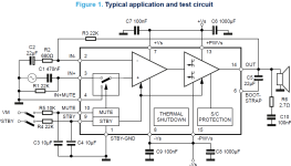
In an old active three way loudspeaker of a friend one of the TDA7294 has firmly blown a hole in itself. No apparent cause. After cleaning the board from black dust, the surrounding standard components on the standard pcb layout measure fine. The mute is not used. The loudspeaker unit of this mid channel measures ok.

After replacing the TDA7294, an offset of 0,4Vdc appears (input shorted). It can be traced back to the IN- by measuring the voltage at that input in relation to ground.
Without power supply R3 = 22k measures fine.
The other two TDA7294 on the pcb of this loudspeaker measure fine, hardly any offset at the output.
The voltages of the power supply are a stable + / - 25Vdc. The scope shows no sign of oscillation.

What may cause the offset of 0.4V ?

Attachments

  • TDA7294 Basic schematic.png
    TDA7294 Basic schematic.png
    78.6 KB · Views: 108

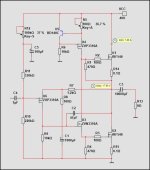
MOSFET Input, MOSFET VAS, MOSFET Output = 18 Watt

ALL MOSFET Amplifier.
THD at 1 Watt is 0.0008%
Harmonics shows most H2 and a bit H3.
Output should be at 17.9V and the bias is 1.20A.
Max output is like 18 Watt.
Tranformer should be 2x15VAC or 30VAC for like 40VDC supply.
Enjoy!

Attachments

  • MOSFET ALL_02 Fourier.jpg
    MOSFET ALL_02 Fourier.jpg
    59.2 KB · Views: 352
  • MOSFET ALL_03.jpg
    MOSFET ALL_03.jpg
    46.5 KB · Views: 215

GAYA2-Final, finishing the unfinished after 15 years

I designed and built my current system during 2006, it is a WWMT with Scan-speak 21W8555-01 8" woofers, Accuton c2-6-78 midrange and Accuton c30-6-24 tweeter, height some 110cm. Due to other priorities i had to stop spending time on speaker design and thus remained some unfinished work on my speakers as of 2007.

opstelling.jpg

Current set up in living-room, 5.3m wide and quite asymmetric, to the right there is another small room ;-)

A few of years ago i started to look into this matter of speaker design again, studied the publications on the subject (Toole, Griesinger, Johnston, diyaudio.com, etc) on design as well as sound reproduction and played with 6mm felt sheets to reduce the unwanted diffraction effects, not much improvement.
Last year just as a "just do it" step i took some absorption panel (cotton, shredded jeans, very difficult to cut), and quickly made something and put it on the speakers.
Some difference!, most striking was the timbre of voices, instruments, stayed much more constant across the room, also more involvement.
EcoAbs-Baffle-01.jpg


I got intrigued, and this spring re-assembled measurement rigs, made a turntable, and together with Arta and VituixCAD started to get experienced again in measuring and analysis. I decided to start basically all over again, be it with the assembled enclosure with drivers as a given. The passive crossover, and any physical adaptations for the edge diffraction, be it within the limitations of the front of the speaker, are to be engineered from scratch.

The objectives:
• Flat anechoic on-axis response, note: will require tilting the tweeter forward as baffle is tilted backwards.
• Smooth off-axis response & early reflections response and sound power & DI
• Distortion focus, be it with given drivers. Note: Filter choices can influence distortion.
• Spurious noises (already non-existent sofar, but the metal grilles are suspect)
• From my experience and listening preference:
- Crossover frequencies: ~435 and ~3465 Hertz (based on the discrimination bands of our hearing, reduction of doppler effect distortion)​
- Sound stage aka dimensionality,​
- separation of the individual voices/instruments​
- left-right & depth​
- Mostly playing at lower levels (< 80 dB), occasionally also louder.​
- Timbre constancy in room at various listening positions.​
- Envelopment (being there sort of independent of the actual living room)​
- Engagement, does the music make me engage, does it trigger emotions.​

This all gave me a starting point in my loudspeaker project, named:

GAYA2-Final: Finishing the unfinished after 15 years

As the name implies it is to finish what I started in 2005 and had to stop end of 2006, engineered to the current state of the art.
Key to being successful is the following: “Through measurements to knowledge” (door meten tot weten) , the quote of Heike Kamerlingh Onnes.

This principle is fundamental, therefore from the desktop research:
  • Arta, Limps and Steps for measurements and some of the analysis.
  • Calibrated microphone
  • VituixCAD for the crossover design and simulation, taking a holistic view on and off-axis and step performance.
  • And very important: Listening test, not only to correlate sims with the reality, also to achieve my perception based objectives.

And when done to incorporate what currently is possible for room corrections in the currently well-developed digital dimension of sound reproduction. I already have purchased Uli’s Acourate Pro and Mitch’s Hang Loose Convolver for this aspect.

The start:
I learned the tools by exercising measurements, study forum and article/book publications and perform analyses to fully understand them, before beginning with the real thing.
To cut a long story short: See also the thread Tmuikku started: https://www.diyaudio.com/community/...sover-and-tilt-experiment.388389/post-7097857

The outcome , quite humbling, is first of all the absorbing matter did make a difference, but also I have to get my measurements correct and repeatedly consistent, including getting rid of some DC error / very low frequency rubbish and the floor and ceiling reflection to get a decent gate in msec. Last but not least, my current baffle-shape for midrange and tweeter needs serious improvement (no surprises there 😉)

So back to the drawing board.

And not to forget enough space around the speaker during measurements, which means temporarily re-arranging the living room, thus only possible when I am alone and having enough time. 😉

Benz Micro Ruby 2 Open Air, for rebuild

Hi,

I am selling this one, Benz Ruby 2 Open Air. https://www.ebay.com/itm/335650663431

Problem is that my cart is completely worn out. Complete rebuilt at Benz (stylus, cantilever and coils new, only body and magnets remain) is between 400 and 600 €. That rebuilt can also take months which is pain, but result should be brand new cart for about 1000 € , normally that stuff new goes for over 2000.

Than again, I never rebuilt cart at Benz Micro, they as matter of fact officially discontinued service, I found way to do it by calling them. In any case , I have no idea if their rebuilt service is reliable ....

Two dome mids in an MTM arrangement……anyone tried it?

So 2” dome mids…….fabric……sound amazing but limited in their lower end response as it relates to power handling……..MAYBE 700hz on a good day with transient peaks. How would I get around it?…….well two of course! Now the problem becomes the C2C spacing……BUT is it really a problem up around 5khz with such wide dispersion driver?………..could a 19mm dome pull off the transition?……the SB Acoustics SB19 certainly has the power handling on paper

https://www.parts-express.com/Dayto...Fabric-Dome-Midrange-8-Ohm-285-022?quantity=1
the smooth response on these is uncanny

https://www.madisoundspeakerstore.c...oustics-sb19st-c000-4-3/4-dome-tweeter-4-ohm/
and just as smooth. I’ve used this tweet before and it’s a hidden gem……just as good as an OM1 IMO

The faceplates of the mids would need to be truncated to get them close as would the face of the tweeter……or mount the tweeter flange over the faceplates of the mids…..closer time alignment sacrificing some diffraction.

GT-1188 Piezo Screw On Driver - KSN1188 alike?

I bought two big horns this type, HL-1018:
hl-1018.jpg


46.3*24.4*21.4cm Wide*High*Deep*

and some real drivers Kenford comp50 with Titan diaphragm.
Not tried until now the classic driver for the horn but bought just for fun a Piezo screw on drivers GT-1188.

And did measure only a response down to 4khz like with the small tweeters like KSN1005 what left me puzzled
th-2991439446.jpg


So did the real Motorola KSN1188 ever really reach down to 800 hz as pretended ? (did not find a measurement online of it).

And is the GT-1188 as a spare part (with internal step up coil) only not working on this big HL1018 horn?

I know that the piezos can never be as good as real coil drivers but is it possible that the frequency response is so far away from covering the claimed response down to under 1khz?

Piezo VS voice coil tweeters

Voice coils, with their endless crossover problems, must be superior to piezo-driven tweeters, since most, if not all of you use them. Is their non-linearity and "scratchy high frequencies" their only downfalls?

Apart from not needing a xover, are there any advantages to using piezo tweeters? How is development of piezo's going? Are they getting better? Will they ever reach close to a par with voice coils in tweeter applications?

Simple, compact, balanced input chipamp

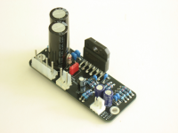
IMG_0590 small.png
My first gainclone build was built on BrianGT's compact (2.9×1.2inch, 75x30mm) boards. While these days I like larger boards for my builds, I've always liked the challenge of fitting better performance in this small form factor.

So here it is again, this time, with a balanced input and even lower distortion and better sound, using "normal" size (i.e. D=2.5mm L=7mm) axial resistors instead of compact ones.

I am posting some pictures for now and will update this thread in the coming days.

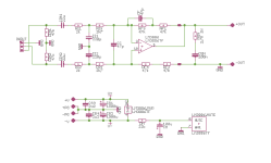
Schematic:
1744213016332.png

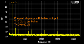
THD 1kHz 1W 8ohm (0.0010%):
THD 1kHz 1W 8ohm small annotated.png

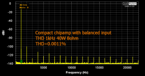
THD 1kHz 40W 8ohm (0.0011%):
THD 1kHz 40W 8ohm small annotated.png

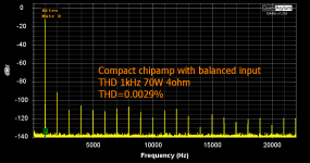
THD 1kHz 70W 4ohm (0.0029%):
THD 1kHz 70W 4ohm small annotated.png

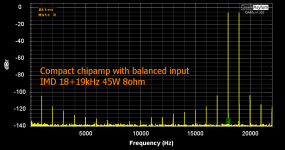
IMD 18+19kHz 1:1 45W 8ohm:
IMD 18+19kHz 45W 8ohm small annotated.png

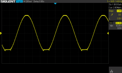
Clip 1kHz 4ohm with +/-28V power supply rails:
Clip 1kHz 4ohm 2x28V rails.png

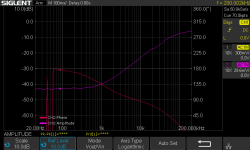
CMRR (1% resistors, balanced source):
CMRR.png

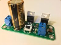
4A - Ultra low noise regulator LT3042 based with synchronous rectifier - evotronix.eu

4A - ULN regulator LT3042 based, with synchronous rectifier - evotronix.eu

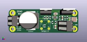
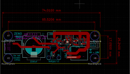
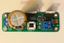
Zeno MKII - ultra low noise regulator based on LT3042 and powered by synchronous rectifier - Saligny LC inside 🙂
This is perfect regulator for RPi projects, Shigaclone, digital section in any DAC, etc.

Specs:
- input min.6Vac up to 14Vac, max.16Vac
- output any voltage up to 15Vdc
- max output sustained current 4A

Output voltage can be changed by R7 value.
R7 = Vout x 10Kohm


PCB + Saligny LC = 30euro shipped by tracked mail envelope 8euro.
Full mounted = 65euro shipped by tracked small parcel 22euro EU, 38 euro worldwide.
For EU citizens, 19% VAT is not included and will be added at the end of your invoice.
For EU VAT registered companies, there is no VAT.
For outside EU citizens there is no VAT.


Invoiced payment by PayPal - fee ~4%, or bank transfer.

Regards,
Tibi

Attachments

  • ZenoMKII-1-300x225.jpg
    ZenoMKII-1-300x225.jpg
    12.4 KB · Views: 754
  • Zeno&Saligny.png
    Zeno&Saligny.png
    130.7 KB · Views: 703
  • Zeno MKII PCB.png
    Zeno MKII PCB.png
    56.6 KB · Views: 701
  • ZenoMKII.jpg
    ZenoMKII.jpg
    209.6 KB · Views: 906
  • ZenoMKII.png
    ZenoMKII.png
    360.7 KB · Views: 834

HI all newbie diy boi reporting!

Hi. I'm Desmond from Singapore. I call myself an audiophile but i'm pretty sure i'm just another amateur in the hobby. I have engineering backgrounds and as always, College/University only teaches that much of theory and not much of practical.

My aim is to design my own amplifiers and might even step up to things like DSP/EQ/DAC with guidance and support 😀. But first off, I want to design a portable audio amplifier. Please help me!

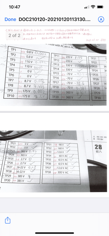
Common Assembly issue TU-8600S

99% of the time, problems when building the amp come from soldering issues and installing components in the wrong polarity.
The following is a common example. The amp was fixed by Mr. Fujita just today.
Here is my suggestion. Please follow the manual step BY step.
When you finish the main PCB. Please cross reference to the floor plan from the manual


C116 and Q102 are installed incorrectly.


In addition, some soldering points are not covered by solder.
Correct polarity....


ReD: after repair
Pencil : before repair


flags_1

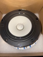
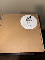
For Sale (Quick) Mark Audio’s MOAP 11 Drivers Pictures and prices dropped.

(Update) all sold. Thanks everyone. I don’t know how to change the tile so am reposting this add.
🌟The Buyer pays for shipping unless otherwise on the Audio products being sold.


Pending/(update) 4-13-2025. So Am willing to trade for a pair of Fostex FE206En drivers and maybe some cash. A. Mark Audio’s MOAP 11 Full Range Drivers brand new on the box never used.
$347.90. my price on these drivers. That’s 50% off with the tax I paid which is $647.90 for both drivers . No low ball offers please. Buyer pays for shipping. E mail for offers and speaker pictures of the fostex FE206En drivers.

Sold/B. Mark Audio’s Puliva Seven HD in copper color. Asking $50.00 A pair. Buyer pays Shipping.

Sold/ C. Mark Audios CHN-50P Paper drivers. Brand new never used in the box. Am asking $20.00. Buyer pays for Shipping.

Fostex Full Range Drivers.

Sold /A. Fostex FE126NV drivers Brand new in box.
Asking $95.00 a pair. Buy for pays Shipping.

Sold/B. Fostex FE126E Drivers Brand new in box. Asking $85.00 a A pair. Buyer pays for shipping.

Dayton Audio.

Sold/ A. RS125 5” inch drivers. Am asking $45.00 a pair. Buyer Pays for shipping.

Completes speaker boxes for sale.

sold /1. Frugal Horn XL for Sale am asking $100.00 for the pair. Offers are welcome if wanting to e mail me? No low ball offers please.

If you have any questions please ask? My E- Mail is;

Jmboo1922@gmail.com.

I no longer have the following Items which have been all sold.

1. Fostex FF165K Enable drivers.

2. Vifa /Peerless Ring tweeters.

3. Paper tweeters (buy out at Parts Express).

Attachments

  • IMG_6045.jpeg
    IMG_6045.jpeg
    782.5 KB · Views: 40
  • IMG_6044.jpeg
    IMG_6044.jpeg
    683.6 KB · Views: 38
  • IMG_6039.jpeg
    IMG_6039.jpeg
    744.5 KB · Views: 36

Ah! Njoe Toeb 4000 suddenly inop

My purchased-new Ah! Njoe Tjoeb 4000 has suddenly gone inop (hasn't been used for a few months, in a cool, dry-enough enivorment, but has always worked perfeclty fine up through the last time I ran it late last year.). It powers up, spins, plays, but nothing comes out from the analogue output (a very faint hum when the pre amp is cranked). I have not tried the digital out yet as I have the upsampler board and reportedly there is no digital out with that board present.

I will try to remove the upsampler board (matter of putting in DAC(?) chips where 1 is different from the other 2 (all 3 8 pin) so I will have to figure out which goes where., and see if it works with digital out.

The fuse mentioned in other forums/threads has continuity and the power relay is working. I don't have any spare 6DJ8 tubes handy but both are warming up and I would imagine the likelihood that both suddenly blew is unlikely.

None of the myriad of caps are bulging. The previous 99 CD was supposed to have leaking caps.

Any hints, or a service manual? Ah! appears to have gone out of business years ago.

TIA

Nelson Pass A75 (A40)

Hello.
This is my modified A75 amp - maybe just an A40 from Nelson Pass. It worked the first time it was turned on and has been working great for 2 years.
The chassis is still not made, but it still sounds good.

Attachments

  • A75_vstup.pdf
    A75_vstup.pdf
    94.4 KB · Views: 312
  • A75_vystup.pdf
    A75_vystup.pdf
    44.2 KB · Views: 182
  • Stabilizator2.pdf
    Stabilizator2.pdf
    27.9 KB · Views: 149
  • Ochrany.pdf
    Ochrany.pdf
    77.2 KB · Views: 159
  • IMG_2334.jpg
    IMG_2334.jpg
    676.2 KB · Views: 426
  • IMG_4201.JPG
    IMG_4201.JPG
    535.8 KB · Views: 423
  • IMG_4208.JPG
    IMG_4208.JPG
    596.6 KB · Views: 389
  • IMG_4214.JPG
    IMG_4214.JPG
    649.3 KB · Views: 429
  • IMG_4217.JPG
    IMG_4217.JPG
    659.4 KB · Views: 453

Tidal vs Qobuz vs other streaming services

I wasn't quite sure if this should go in Digital source or PC based so I'll put it here.

I was interested to hear from anyone who has used Tidal or Qobuz on a high quality system (eg not earbuds, car etc) and what they thought of the sound quality, music catalogue etc.

First a confession. 😱 Like many of you I build and tweak speakers and take sound quality very seriously. For many years I used to "sample" music online and anything I liked enough I bought on Redbook CD...

Then when iTunes switched from 128kbit DRM AAC to 256kbit non-DRM AAC I got a bit lazy and started buying albums from iTunes knowing full well that they didn't sound quite as good as an actual CD...but they sounded "close enough" for most music, and could still sound pretty good on a good system, and convenience was the driving factor.

Then a number of years after that I first tried Spotify, lured in by the low monthly cost and more or less unlimited access to browse and instantly play nearly any music and got hooked on the easy discovery of new music. I figured that anything I really liked I would buy the CD's for, but I never did! 😱

Some of you may know that Spotify is alone in using Ogg Vorbis with other services using either MP3 or AAC. Personally, I don't like the sound signature of Ogg Vorbis. Of the three I would rate AAC as the best with Ogg Vorbis considerably worse and MP3 marginally worse than Ogg Vorbis.

My music collection has been a mixture of CD's, CD's ripped to Flac, CD's ripped to AAC, older "acquired" MP3 rips, and Spotify, and after moving country once and house twice since then I no longer even own a CD player, despite keeping my CD's for possible future ripping to FLAC.

My main digital music playback system is now a Raspberry Pi 4 running Volumio with a Behringer UMC204HD USB DAC.

I was recently going through some old CD's and decided to try playing one for the first time in years - the only thing I have that will even take an optical disc now is an Xbox one! This goes to the TV via HDMI and the headphone analogue output of the TV then goes to the amplifier. Hardly an ideal signal path - fine for watching TV Shows and Movies but not what I would want to use for Music.

Surprisingly or perhaps not surprisingly despite this tortuous signal path there was no doubt that the CD played via the Xbox one and TV to the amplifier sounded better than the Spotify version of the album through a much better quality DAC. Much better. I tried many CD's and the result was the same - I had forgotten how good CD's sounded compared to lossy codecs after years of conditioning (brainwashing ?) by listening to lossy audio... 😱

I decided enough was enough and that it was time to research music streaming services that offer lossless audio, which didn't exist back when I first joined Spotify many years ago but now did exist.

So I came across Qobuz and Tidal who seem to be the two main players right up until the very recent announcement of Amazon Music HD. (More on that later)

As it happens, Volumio with the MyVolumio subscription supports full quality playback of both Tidal and Qobuz out of the box, (as well as playing my local FLAC, AAC, MP3 content and Spotify as well) making it very easy to do direct comparisons of the different sources using the same software and same DAC.

So I signed up for a free month trial of Qobuz which runs out in about 10 days and recently signed up for a free month trial of Tidal as well so I can do a direct comparison within the trial periods. So far I have listened more to Qobuz than Tidal since that trial runs out first but here are my thoughts so far on sound quality:

In short Qobuz sounds fantastic. 😀 Although you can choose to play MP3 versions of songs if you want (for example over 3G/4G on your phone when using ear buds to reduce data usage) all but a very very few tracks have at minimum CD quality FLAC at 44.1Khz 16 bit available.

Those songs that are CD quality literally do sound indistinguishable to my actual physical CD's that I had ripped to FLAC previously, and far superior to Spotify's lossy Ogg Vorbis versions of the same albums.

I have no doubt that they are using perfect FLAC rips of CD masters, so sound every bit as good as buying a CD, ripping it to FLAC yourself and storing it on a local media server.

A surprisingly large number of albums, both old stuff that has been re-digitised and current releases are also available in "Hi-Res", with Hi-res meaning 24 bit and/or >44.1Khz, and they show up with a separate badge in the listings, and when played in Volumio the sample rate and bit depth is indicated.

There seem to be a wide variety of sample rate in use depending on the specific album.

I've seen 44.1Khz 24 bit, 48Khz 24 bit, 88.2Khz 24 bit, 96Khz 24 bit and 192Khz 24 bit. My Behringer DAC supports all bitrates and bit depths natively without any resampling.

I'm now in my mid 40's and last time I checked my hearing only goes up to about 16Khz instead of the 18Khz it did in my 20's.... traditionally I've been a bit sceptical about "Hi-Res" formats as the higher sample rates in particular seem to be wasted if 44.1Khz will already work up to 22.05Khz and I can only hear up to 16Khz...

So do they sound any better than CD quality ? Despite my initial scepticism I would say yes, some of their Hi-Res tracks do sound slightly better than the CD versions. It's hard to describe subjectively (I'm more of an objectivist) but there is something about the smoothness and naturalness of the treble and separation of instruments and sound field that is undeniable. It sounds slightly cleaner and more spacious but at the same time effortless without any over emphasis of the high frequencies. Sorry but that's the best description I can give it.

The difference is not huge but it was noticeable with the right playback system and on many but by no means all albums. If I had to come up with a scientific explanation I can think of two possibilities, given that I don't believe in sound frequencies higher than our hearing limit having any impact on what we perceive.

One is that sampling at only 44.1Khz means your anti-aliasing and reconstruction filters have to cut off before 22.05Khz, and if you are trying to include all frequencies up to say 20Khz without attenuation, that's is a very steep filter needed to do that. That filter is inevitably going to have either phaseshift or time domain effects within the audible spectrum which may be audible. And if the filters are not done properly musical content above 22.05Khz may be folded back into the audible spectrum and this is likely to be audible as well as aliasing which may add something artificial to the top end.

Sampling at 96Khz means you can use much shallower more benign filters and also place their cutoff frequency WAY above the audible spectrum so that the filter skirts don't impinge on the audible spectrum at all. Having said that I think going to 192Khz is a complete waste of time over 96Khz, and I did not hear any difference between them, nor was I expecting to.

Something else to consider when comparing 44.1Khz and 96Khz even on the same DAC is that the DAC itself switches to different reconstruction filters for each sampling rate, and that may have an impact on the sound.

On my Behringer which I also use with ARTA for speaker measurement, at 192Khz it is of course ruler flat well beyond human hearing as measured in loopback, however at 44.1Khz there is a small rolloff in the upper treble starting about 15Khz before it drops rapidly at 20Khz. Would this "premature" droop be audible ? Possibly.

Possibility two for why the Hi-Res versions might sound slightly better is simply that the "Hi-Res" masters are probably sometimes different masterings of the original recording, and there's no easy way to know this.

I've read about some albums which when released in "Hi-Res" have had less dynamic range compression applied during mixing, and this of course would likely make it sound better especially if the original release was made during the loudness wars. So in that case the Hi-Res version of the song definitely sounds better, but not due to its sample rate or bit depth but simply because it was mastered better, and a version of that downsampled to CD quality would likewise sound better as well if it had been available.

But if all that is available is the original CD mastering with more dynamic range compression and the Hi-Res remastered version that has less dynamic range compression, then I say listen to and enjoy the Hi-Res version, just don't necessarily assume that it sounds better due to higher bitrate or sample depth!

I noticed these differences in mastering in for example a Moody Blues album where there are at least 3 different versions of the same album on Qobuz. One of the CD quality versions sounded just like the original LP I remember from years ago with a slightly strident and forward midrange on the vocals and a little bit of edginess on strings.

The Hi-Res version sounded better tonally balanced and slightly more laid back and easier on the ears especially in the midrange - clear but clean and much easier to listen to. Clearly the remastering engineer has gone in and applied different EQ to the individual channels and rebalanced the mix and in my opinion it sounds much better and more like a (good) modern recording.

Anyway, after two weeks I'm super impressed with the sound quality of Qobuz, especially to a full size stereo system with a good quality DAC that can output the "Hi-Res" tracks at their native sample rates. The CD quality tracks sound exactly like FLAC rips and there are a surprising number of albums in Hi-Res formats which all sounded at least as good or slightly better than the CD quality versions. I'm finding myself enjoying the music much more again and have spent quite a lot of time listening during the trial period.


Next up is Tidal. They also have CD quality 44.1Khz 16bit FLAC available for most songs, however I have come across a few albums that are only available in MP3.

From what I have listened to so far Tidal's CD quality FLAC sounds identical to Qobuz's CD quality FLAC, perhaps not surprisingly, except in cases where a different master (remastered vs original etc) has obviously been used, and as the labelling of some of the releases between the two services can be a bit inconsistent you can sometimes end up listening to a different release of the album especially with albums that have been remastered more than once.

Where they differ is that for "Hi-Res" Tidal uses something called MQA, and that's where a can of worms starts to open up. 🙄

Instead of the open, lossless FLAC codec used by Qobuz for Hi-Res, MQA is a weird Frankenstein proprietary codec that is partly lossless and partly lossy. For the full gory details of what I think is wrong with it and why I don't like it on a conceptual basis, I direct you to the following article:

MQA: A Review of controversies, concerns, and cautions - Reviews - Audiophile Style

To boil it down to it's simplest, it has a lossless PCM base encoded in the most significant bits at 44.1Khz or 48Khz onto which additional "detail" for higher (than 20Khz) frequencies is encoded using a lossy codec whose data is encrypted and encoded into the least significant bits. Figure 7A of that article explains it.

To play an MQA file at its full quality you need a hardware DAC that can "unfold" the file and process it back into its original state.

If you play it on a regular player then this additional "detail" is not retrieved. Because the least significant bits of each sample are effectively pseudo random noise (encrypted data looks like noise) that undecoded data would manifest as a slightly higher than normal noise floor - the article suggests that an MQA file played without a decoder would be equivalent to about 44.1Khz 13 bit...so not quite as good as Redbook CD without a decoder.

When fully decoded the lossy part of the data is combined with the PCM part to increase the bit depth and sample rate to 96Khz 24bit, but remembering that frequencies above 20Khz and bits below 13 bits have been processed through a lossy codec.

In short its a clever way to create a hybrid lossless/lossy codec that can "play" on anything but only play at full quality with the right MQA licensed hardware. Supposedly the file size is around 1/2 to 1/4 of FLAC at the same sample rates.

My biggest issue with MQA is simply that I want to move away from lossy codecs back to lossless, so why would I want to jump onto a weird hybrid proprietary codec that needs special hardware support (which I don't have) for full performance and probably sounds worse than Redbook without suitable hardware... ?

Five years ago when bandwidth was less than today I could see the point but today there is enough bandwidth to simply stream FLAC at high bitrates - and Qobuz proves that. So I think MQA is a solution looking for a problem that no longer exists, and in the process throws the baby (lossless audio) out with the bathwater!

I've played a number of Tidal "masters" as they call them with MQA, however I don't have a DAC that can decode them, so my only comment is that they sound "fine" but don't sound any better than the CD quality version of the tracks. So in my situation if I was to subscribe to Tidal I would stick to the CD quality FLAC streams as I'm not interested in buying an MQA compatible DAC when I don't believe in the philosophy or rationale behind it. If there is enough bandwidth available, just stick to FLAC in my opinion.

In terms of numbers of "Hi-Res" tracks, Qobuz seems to have far more Hi-Res FLAC tracks available than Tidal has MQA masters.

In the next post I'll briefly compare catalogue, iOS/desktop apps and pricing and then my conclusions, as well as a quick mention of Amazon Music HD.
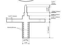
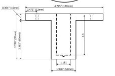
Hello from the edge of the northeastern Pacific (western Canada)

New member trying to maintain old equipment and save money.

For source,

Oppo BD-105
PCs running Asus Xonar card (2 flavours of connectors, PCIe and the other one_
The main one of interest and why I joined, Ah! Njoe Tjoeb 4000 which has suddenly gone inop

Also have this Audo Nemesis VLE-1 LE DAC which I will have to use now as the Ah! is not working (will try to get it to work as a transport, no digital out due to the upsampler board).

For pre amp
Counterpoint SA 7 (.1?) updated by Counterpoint
PSVane T-417 would like a pair of monoblocks to go with it


Power amp
2 Alta Vista NP-100s which were COunterpoint SA-12s in an earlier life

Magnepan II, IIA. The IIs need regluing but question whether it is worth the effort.

Oh yeah, also an Elipson t/t

How important is fT Gain Bandwidth when choosing BJTs?

I'm assembling a parts list to restore an integrated amplifier from the 1960's, I haven't tested the preamp & driver transistors yet but I would like to have backups on hand to avoid starting and stopping in the event one is bad.

With the exception of the outputs, all others will need to be substitutes since the originals are now obsolete.

The outputs are 2N3055 and have a fT of .8 MHz (min) to 6.0 MHz (max). Do the replacement transistors in the preamplifier and driver stages need to fall in this range?

Accidental MLTL Technique

Do you have a favorite driver that you would like to use in a mass loaded transmission line (MLTL) like a TABAQ, Pensil, or Metronome, but no one has yet run a simulation for it with MJK's software? Sometimes, folks on this forum can be very generous with their time and provide you a simulation if you ask. I have seen Bjohanessen do this many times for me and others. But in case you do not have the fortune of a full-blown simulation in MJK, but would like to hear what your driver sounds like in a MLTL, this thread is for you.

Let me first say that, this is not meant to replace a real simulation, but is rather an observation I have noticed that has worked a few times. I imagine that there are drivers where this will fail. For MLTL's where you want to push the tuning frequency below the natural free space frequency of the driver, choose a driver with a moderately high Qts (> 0.5).

This idea arose out of something I noticed happening on several occasions with a good result. I call it the 'accidental MLTL' technique because it may have been luck or chance but it seems to work a few times now for me (and at least once by others). I originally posted this in Bjohanessens's TABAQ thread but figured it was enough to spin off a new thread. I will repeat that post here...

If you happen to have MJK's MLTL worksheet, give this a try by running a simulation with your driver and running WinISD and calculating the CSA, length, and vent and compare the two. It would be interesting to hear your results.

----

Use WinISD bass reflex software (free) and plug in your driver's T/S params and design a vented bass reflex speaker enclosure using the default optimal case. That will give you the volume of the box and the vent cross sectional area and length.

Now choose a maximum length you are willing to have based on practical size constraints, typically 30 inches to 40 inches long. This will correspond to a quarter wave length that is probably higher than the tuning freq of the bass reflex design that came out of WinISD (circa 60 to 75 Hz).

Calculate the cross sectional area (csa) of the transmission line using volume from WinISD and the length you set. If the csa is bigger than you prefer, you can go off the optimal case by going back to WinISD and adjusting the box volume manually to a smaller value and tweaking the frequency even. You can play with the vent to get it to a diam and length you like. Typically, I do this because the default vent is not very practical. Then use new box volume and vent dimensions to calculate the new csa based in length of the line again.

Now build the enclosure with the csa and length and put a vent with dimensions from WinISD at the distal end. On the closed end, measure 1/3 of distance down and make cutout for driver and mount it there. Put polyfill stuffing from closed end to about half to 2/3 of the way down the line. Adjust this to taste, less stuffing gets more boomy bass. More stuffing gets tighter bass at expense of amplitude. I have found that the position of the driver need not be exactly at 2/3 and indeed can even be at the closed end.

Doing this approach will guarantee that at worst, the speaker will perform as a bass reflex optimized for volume and vent size. But if physics of a MLTL and quarter wave theory kick in, you will end up with a speaker that has deeper bass extension than predicted by WinISD. The speakers that I have built following this recipe have measured very well when I look at what is coming from the bass port - typically, I get the low frequency extended or 'pulled down' by an additional 15 Hz from the plain bass reflex prediction. The speakers also sound great - very balanced when the bass port output integrates with the direct radiation from the driver.
If you want to experiment without investing too much in wood, use foam core to build quick and dirty speaker. Even cardboard can be used as a test speaker for this.

----

Here are the two examples that have worked for me:

http://www.diyaudio.com/forums/full-range/223313-foam-core-board-speaker-enclosures-148.html

334668d1362710759-foam-core-board-speaker-enclosures-p1040132.jpg


http://www.diyaudio.com/forums/full-range/223313-foam-core-board-speaker-enclosures-109.html

325364d1358742082-foam-core-board-speaker-enclosures-p1030849.jpg


A third example not by me might be Cogitech's "nano tower" speaker with the ubiquitous TB W3-881si. Which I think was also designed as a bass reflex with WinISD but due to its slender aspect ratio and length, happens to have some very nice bass deeper than one would expect based on accounts from builders.

http://www.diyaudio.com/forums/full-range/200912-nanotower-tang-band-w3-881si.html

250537d1321853244-nanotower-tang-band-w3-881si-nanotower.jpg


Update : 4th example is a quad driver bipole with W3-881si http://www.diyaudio.com/forums/full-range/234535-tangband-w3-881-mltl-build.html

345228d1367098124-tangband-w3-881-mltl-build-tangband-w3-881-mltl-build-024.jpg


Fifth example is a folded AMLTL with a Vifa as wall or bookshelf speaker:
http://www.diyaudio.com/forums/full-range/231951-accidental-mltl-technique-16.html#post3466655

345087d1367034174-accidental-mltl-technique-photo-7339508392.jpg


344601d1366813569-accidental-mltl-technique-folded-vifa-amltl-01.jpg
  • Like
Reactions: ziffel

For Sale Iron Pre SE - Essentials Kit

Sold.

Up for sale is an Iron Pre Single-Ended Essentials kit. This is the early-release version as shown in the photo. The parts bag has been verified complete, and the kit includes two Cinemag CMOQ-4HPC, main board and a twister board. $160 USD + shipping. I prefer to use Paypal F&F since we are all friends here at diyaudio. Will ship double boxed. US/Canada only, please. Thanks!

DSC02320b.jpg

DIYing TAD TH-4003s...

I'm planning out a build of a TAD 2404 "inspired" build with a clone of the TH4003 horn. I sketched out the horn top, bottom and side profiles in Fusion 360 from a copy of a TH4003 spec in this post here: https://www.diyaudio.com/community/threads/new-project-tad-2404-clone.322939/post-5440074
Let me know if anything looks wrong in my dimensions or if there are better sources of plans available.
When I get the 3d model put together I plan to model in ABEC3/Akabak which I have not had much luck with in the past.
I will be using a benchtop CNC router which should be just big enough for this project by a cm or two in every direction. Either Douglas Fir or western (big leaf) maple for the first version. The horn will be made in four parts: top, bottom, and 2 sides. I also plan to make the throat adapter on my CNC from sandwiched plywood.

Given a single used D-4003 compression driver costs more than my entire budget for this project I am planning to make a throat adapter to allow me to use a 1.4" compression driver. The Radian 745 NEo is currently at the top of my list but open to suggestions.
For the woofer the B&C 15PS100 and Cair 15NDH-4S model pretty close to the TAD TL-1601 in my WinISD models, but I may just spring for a used pair of TL-1601s.

I will be running this active with a MiniDSP and a 4 channel Bryston 7B, with crossover around 650hz. So no passive crossover at least to start with.

Attachments

  • side_th4003.png
    side_th4003.png
    467.7 KB · Views: 88
  • top_th4003.png
    top_th4003.png
    464.8 KB · Views: 84
Projects by fanatics, for fanatics
Get answers and advice for everyone wanting to learn the art of audio.
Join the Community
507,508
Members
7,875,122
Messages

Filter

Forum Statistics

Threads
405,628
Messages
7,875,122
Members
507,508
Latest member
Stevis05