For Sale Got some Belden 8412 for RCA and XLR interconnects

I have a ton of Belden 8412 RCA and XLR interconnects made with Neutrik XLR and Switchcraft 3502a and I am looking to sell cables here. I have some made up ranging from 1 meter all the way up to 15 feet and I have approximately 20 feet of extra cable where I can make custom sizes.

The 8412 is claimed to be a replacement for the highly rated 8402 cable. It just has a black jacket but uses the same internal wire and conduit. I really like the sound of these cables in my system and plan to keep a couple pairs for myself.

I was going to price them for the cost in materials to make them:
  • RCA Pair - $15 plus $2.50 per foot
  • XLR Pair - $20 plus $2.50 per foot

Selling these and shipping from Houston. Shipping not included in the price above.

Calling DAC experts for ultimate PCM63 DAC

I would like to build(I will use assitance form local experts, as my digital knowledge are very limited) a dac with 8x (or 16x) pcm63p-y chips . fully balanced (1xpcm63 for phase, minimum 4 psc required for stereo xlr output) Money is not issue(have the chips and still many black gate N left) on the design , so feel free ofer compromiseless sugestions. dac will be fed from usb/spdif/i2s converter.

however lot of questions- even before deciding haw to go-

1) what logic chips needed to conect i2s to pcm63(without digital filer and receiver) if not possible then-

2)is it possible to use digital receiver wm8804(or any similar quality chip_ straight to pcm63(without digital filter) if yes , what parts is needed.

3)are there some better.new filters than sm5842APT, which can be used with pcm63.

4) is it possible to run pcm63 straight to power amp input- a) without any circuit(just IV resistor) b) trought transformer at this stage I am not considering discrete IV(like pass labs d1, or zen IV which is fine with 4xpcm63)) with 16x pcm. I belive 16x pcm63p will have enought current???

aditional questions -how to drive 16xpcm63pk(several digital filter,receivers or logic chips needed? I believe it cant be done with just ordinary schematic for 2 or 4x pcm63)

maybe some pcm63p implementation ideas?

will wait answers to what direction its best to go.


P.S. yes I have moder DAC's (with ess9018,1794 ) but always dreamed to have OLD dac with pcm63
I also have a old style dac (with wm8804>>sm5842apt>>4x pcm63p-k>>jfet output stage) which I like the most, and would want do better, or to say best.

thanks again for reading, and hoping to get some advices..
  • Like
Reactions: head_unit

Question about optimizing PFFB for TPA3245

I am reaching out for comments and suggestions regarding the PFFB and the TPA3245 configurations. The goal is to create a hybrid amplifier with tube input stages and a power amplifier stage using the TPA3245 with PFFB. Further assumptions include an 8-ohm load impedance. I am not interested in a race for output power, as, in practice, achieving peak power on the order of 10W is practically impossible since it can become too loud for others two floors up or down, often resulting in a police visit. Please do not comment on this, it is simply the reality. Playing with a maximum power of 10-15W is more than sufficient for an average apartment with speakers that have an efficiency of around 90-91 dB/W.

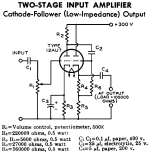
Returning to substance, I have already explained why the TPA3245 is sufficient (the TPA3244 would also be enough, but the powerpad facing down complicates things for an amateur hobbyist) and why I have chosen 8-ohm impedance. I will inform you about the tube stages, with the first being a regular RC stage and the second being an inverter with split load. Following that, there will be voltage followers using operational amplifiers, which unfortunately is due to the desire to implement PFFB. The driving impedances for the power stage must be very low and, ideally, identical. This is not achievable for tubes without using large tetrode/pentode tubes, which, in my opinion, defeats the purpose.

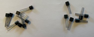
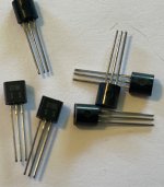
The choice of tube type is quite straightforward and obvious — subminiature double triodes 6N28B-V from Soviet Union, which perform excellently at low voltages. They are more readily available than Soviet nuvistors 6S63N. Regarding both types of tubes, due to having a curve tracer, I have characteristics in the interesting range of voltages and currents along with matched SPICE models. The gain of the tube stage should have a reserve of 8-10 dB to meet consumer standard requirements - around 320 mV rms. Again, please do not comment on this, I have signal sources that only provide audio signal at that level. Adding a switchable attenuator to the amplifier input is not a problem, so around 100-150 mV rms and 600-800 mV rms. As mentioned, there should be some headroom since the audio material does not always reach an average level of -6 dB (which is catastrophic), and the tube wears out over time.

Now, another aspect is the modulation frequency for the current switches in the TPA3245. Definitely 600 kHz. The higher, the better, since the cut-off frequency of the LC filter at the output can be higher, thus having less effect on the transfer characteristic in the acoustic range. The higher the switching frequency, the more accurately the highest frequencies are reproduced. I am not concerned about efficiency drops; fighting for 2-5% efficiency is pointless. Of course, there is also one argument against raising the switching frequency: the dead time of the current switches. Circuits like the TPA3116 or the newer enhanced TPA3126 allow switching at even 1200 kHz, and I have not observed significant side effects in practice. I assume that the TPA3245 has a more complex PWM modulation scheme. I remind you that the load impedance is 8 ohms; I am even less interested in 4 ohms.

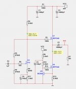
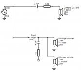
So the first task is to calculate the values of the LC filter components. I took a Q factor of 0.95 as a starting point, meaning a slight "bump" introduced by the filter. In the case of an open output, a resistor of 2200 ohms will be permanently connected to the output. Before the LC filters, I decided to add LC snubbers (10 ohms and 330 pF). The Zobel networks are somewhat "delicate" (1 ohm and 47 nF) because simulations showed, in my opinion, that there is no need for "stronger" ones.

Another assumption is that the passband for a +/- 0.5 dB deviation should not be worse than 10 Hz - 20 kHz. Such a narrow deviation means that after engaging the PFFB loop, the boost just outside the acoustic band cannot exceed 0.5 dB for a resistive load of 8 ohms. The capacitances at the inputs of the TPA3245 can be high since the gain drop of the amplifier inside the loop for the lowest frequencies will generate additional distortions. Limiting the bandwidth from below will occur before the TPA3245 in the tube stage.

A few tests resulted in the values provided in the schematic.

Schemat.png


In the rectangle bounded by the dashed line, we have a simplified model of the TPA circuit, with two added capacitances (C21 and C22) limiting the passband, which is necessary since the bandwidth of the circuit enclosed in the PFFB loop significantly affects the resulting frequency characteristic and has a significant impact on ringing visible for rectangular waveforms.

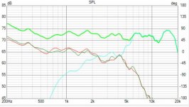
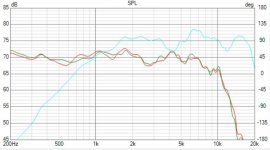
I plotted frequency characteristics for several values limiting the bandwidth of the TPA circuit. The overshoot does not exceed 0.4 dB, which I consider a very good result. Another observation is that the overshoot varies, reaching a maximum, and then decreases as the bandwidth of the TPA circuit narrows.

Bode.png

Green, blue, red, cyan, purple, gray => C1 and C22 values: 0.1 pF, 1pF, 5pF, 8pF, 12pF and 20pF.

The next step is to calculate the attenuation of the carrier frequency. I achieved a result better than 32 dB for 600 kHz (34 dB). For full output power of 35W, this means that with such attenuation, the power dissipated on the load is less than 15 mW.

LCdamp.png


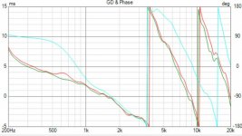
Now, regarding the rectangular waveform. I assumed very steep rise times of 100 ns. For 8 ohms, the simulation results are excellent.

Overshoot.png

Green, blue, red, cyan => C1 and C22 values: 0.1 pF, 1pF, 5pF, 12pF.

Now for the 2200 ohm load - no connected speakers.

OversootOpen.png

Green, blue, red => C1 and C22 values: 0.5 pF, 5pF, 12pF.


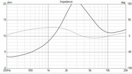
Up to a certain point, it looks good with negligible ringing, but beyond a certain threshold, unfortunately, we move to persistent oscillations. The same is true for the suggested values of the PFFB loop components provided by TI. Analyzing the PFFB publication for TPA3244/45/50/51/55 leads me to conclude that the capacitance introduced into the simplified TPA model in my simulations does not exceed 10 pF.

Now, returning to the passband, for this range, the passband with a 3dB drop ranges from 80 to 90 kHz with a broader bandwidth of the TPA circuit than what results from the 10 pF capacitance. I remind you that for a 0.5 dB drop, we have a passband above 30 kHz. Is 80 - 90 kHz bad? No, it’s very good considering that the drop at the upper end of the passband is significantly faster than 6 dB/oct. Let's be honest; how many people, mainly men over 40, can hear 15 kHz? I bet for a significant majority, 10 kHz is a challenge.

Finally, I will revert to the tube stage. The operating point of the 6N28B-V tubes at a power supply voltage of 52-55 V can be set so that for the second harmonic, the distortion level is in the range of -40 to -50 dB, and for the third harmonic, it is 20-26 dB lower. The remaining higher harmonics should be at least 36 dB lower than the second harmonic.

I also want to criticize the race for the THD+N value. In reality, it is a race just for the noise level. Let's look realistically at listening with speakers. The background noise level during the day in an apartment does not drop below 40 dB (away from a busy street). 30 dB is realistically at night, it might drop to 25 dB. Below 20 dB, there is no chance. The SNR value means that if we add that to the background level, we are almost at the pain threshold. Moreover, let’s also consider how recordings are made.

That’s all for now. I would like to request some substantive feedback regarding the schematic and the simulation results.

Regarding implementation, ceramic capacitors will be C0G, then U2J, and finally X7R outside the audio path. Decoupling the power supply pins of the output bridge in the TPA circuit will consist of two 4.7 nF C0G capacitors plus one 1uF X7R capacitor. Further from the IC, there will be two polymer capacitors of 680u. A bit further, closer to the power supply, there will be two 330-470 uF polymer capacitors. The snubber will use a C0G capacitor, the Zobel network will employ the defined values, and the LC filter will utilize MKP capacitors. The tolerance for ceramic and film capacitors will be 5%. Coupling capacitors in the tube stage will be MKS. Any ceramic capacitors limiting the upper bandwidth will be C0G. All resistors in the audio path will be MELF 1%. Standard thick film SMD resistors are only defining the operating mode of the TPA and used in the converters. The output filter coils are Coilcraft UA8013-AL (this is a critical component and should not be skimped on).

THT components will be the polymer capacitors because the SMD electrolytic capacitor housings are unfortunately not very durable. Additionally, these MKP and MKS components will be THT as well as the tubes, potentiometer, and power-on relay. This relay is necessary because the switching power supply that will power the amplifier will be an external device. This is the best approach, as bringing the power supply wires into the housing along with a huge mess of interference (inverters in renewable energy installations, inverters in household appliances) is something better avoided.

As for this relay, a high-inrush industrial relay rated for 20 - 24 A won't work because welding of contacts is guaranteed in DC circuits with low ESR capacitors like polymer ones. I use pre-make tungsten relays where a contact rated for 16A can handle an average current of 800A for 200 us. They are not particularly expensive and can still be easily purchased (but may disappear as they were mainly used to switch prohibited light sources like fluorescent lamps, sodium, mercury, or metal halide lamps).

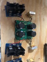
The PCB will be a double-sided FR4 laminate with a copper thickness of 70 um, dedicated to the TPA3245 evaluation board heatsink. The cost is significant; since the components alone will exceed USD 700 for a single board ordered from a reputable company (e.g., Eurocircuits and not from China, since you need to order 10-20 to weed out defects and select a properly manufactured one, and they can also add extra VAT and customs duties in my country), that results in about USD 150.Additionally, there will be a housing plus all this "jewelry" of speaker terminals, knobs, etc. This cost can be criticized, I understand, but if I wanted something cheap, I would buy a cheap product from Aliexpress. Therefore, I do not skimp, and instead of ordinary aluminum capacitors, there will be polymer ones in the audio path.
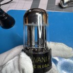
  • Like
Reactions: abstract

DC Offset too high at my FH9 XRK Mod

Hi,
i have build two Amps with a Connex 500R/+-45 Volt SMPS and FH9 XRK Mod boards.
The Amps are working without any problems, but the offset is rather high on all boards. Two boards get an offset of 19/21 mV the other two boards get 26 and 29 mV.

What have i done before...

Tried to measure VGS of the Mosfet belonging to the schematic of Mr. N. Pass. Got luck i could find enough matching pairs for example 4,00 volts VGS for one pair IRFP240/IRFP9240 for a board. The other pairs are not very VGS different, say 4,02 and 4,04 volts VGS or similar.
Took T6 MPSA92 out and choose a 2N5401 as replacement. The 2N5401 has a litle bit higher hFE.
Soldered out the KSC 1845 and matched every pair with my Peak Atlas, without heat and with heating. Finding matched pairs and put them in. For example hFE 420 and Vbe 727.
Nothing helps..the offset remains at high 26 mV.
Changed the KSC1845 to 2SC2240, yeah...50 mV offset...ok, seems not to be the right way....
The mosfet drivers are matched Toshiba TTC004B/TTA004B instead of KSC1381/KSC3503

If i measure PIN 1 to ground at IRFP's i got different voltages. 3,96 volts at the IRFP 240 and 3,74 volts at the IRFP 9240.
Chris, Cherman, gave me an advice to change the gate resistor at IRFP 240 from 220 Ohm to 330 Ohm as a try. Done without success.
If i do that and change the gate stopper both IRFP have less voltages in the same proportion. 3,92 volt/3,68 volt
Another idea was to change the resistor R15 at the driver to the N channel from 47 to 56 ohm or more....nothing...no success
Surely i have controlled every component, resistors, diodes..and so on...
Amp is stable with its offset about 20 mV or a liitle bit higher, no problem to adjust the bias. I choosed 120 mA, 26,4 mV over the 0,22 ohm resistor.

Has anyone an idea what else i can do to lower the offset ? Any idea to make something better is welcome.
Many thanks to Chris, cherman, helping as far he could ...


Greets
Peter

Attachments

  • APEX FH-9 XRK-MOD-COMPACT-side fet-fh9vx-SCH.png
    APEX FH-9 XRK-MOD-COMPACT-side fet-fh9vx-SCH.png
    223.1 KB · Views: 311
  • IMG_20250214_183418[1].jpg
    IMG_20250214_183418[1].jpg
    457.6 KB · Views: 285

Cambridge CD6 sound issues

I have a CD6 bought in or around 2000. It has been stored for years as it had a sound issue in that there is very little low frequency output. This player has both single ended and balnaced outputs, both exhibit the same problem. This player has as it's Dac a first version Dacmagic Dac inside. I think I need to check the opamps on the Dac board and also the voltage regulators to check they are functioning properly. Are there other areas that I should be checking e.g Caps or other components?

Signal strength for SE amp testing?

Greetings Friends. I've been testing my single-ended project amps and have run across some questions about proper use. I'm using a Pyle USB ASIO interface, a dummy load made of thick film resistors wired to present 4- and 8-ohm loads, and an old Lenovo PC running REW.
IMG_20250526_103248706_HDR.jpg


1000007325.jpg

I have a DSO138 oscilloscope and a Klein TRMS-capable meter to directly measure across the dummy load, and a 22:1 voltage divider inside the plug going into the audio interface to limit that voltage to <100mV. This is calibrated in REW and verified with the 'scope.

Ok. I can run Freq sweeps and measure distortion and get pretty graphs. But I'm realizing that without a standard, the measurements are arbitrary. Testing an EL84 Triode amp at 2w output will give a much higher distortion profile than testing a similar amp wired in Pentode at 2 watts, so it's not the output power that I'm after, it's a standardized input signal that I need.

A friend is a guitar amp tech and he recently did an IG post about measuring Guitar amp output power, where he mentioned that the standard input signal for measuring guitar amps is 1Khz @ 500mV. Is there such a standard for Hi-Fi amps?

When using REW, the measurement level can be set in Volts, dbFS, dbu, or dbV. Running a frequency sweep at 4v, for example, causes an input signal to be applied to the DUT that will result in 4v at the output. Setting the level using dbFS results in a similar outcome, arriving at a set output level. Would dbu or dbV give a set input? Am I barking up the right tree here?

Thanks

w

My Balanced Line Receiver

balanced line receiver photo small.png
My balanced line receiver is a small PCB that adds a true balanced input to any amplifier, thus helping to avoid certain problems inherent in single ended (e.g. RCA) connections. Compared to integrated receivers such as THAT1200 series, the board offers an order of magnitude lower distortion (depending on the choice of opamps) and built-in DC removal, which makes a downstream DC blocking capacitor unnecessary.

This project is based on my prior series of volume control boards, which itself was based on Bruno Putzeys' a demo project that illustrated his article "The G-word, or how to get your audio off the Ground", first published in Linear Audio Vol.5. While the focus of those previous projects was volume control, I realized that the combination of a low-distortion balanced input and a ground sensing output is useful by itself, for example, in a monoblock or even a stereo power amplifier.

There was some interest in this receiver in the discussion of our Omicron headphone amplifier earlier this year, so in the coming days I will publish the schematic (post #6 below), measurements and other info on this little board that may be useful.

Thorens TD-125 unstable

Hi everyone,

Something weird happened to my Thorens TD-125, MK1, second board (with one rectifier).
After playing some singles at 45rpm my girlfriend thought she turned the player off but actually set it to 16rpm. The light went out so she thought it was off and it stopped turning.
When I got home I noticed a weird smell and after some searching discovered it was coming from the TD-125. I unplugged it and noticed the metal parts and motorplate were all very warm/hot.

The next day I tested it and 33rpm and 45rpm were kind of working but 16rpm didn't and you could feel it getting warm immediately.

It took the motor assembly to my workshop and recapped the pcb. Now everything is kind of working but there are some problems. The switching of speeds is erratic. Sometimes the motor makes a buzz, and sometimes it turns backwards.
I hooked it up to a scope and noticed the red wire sine-wave was very unstable and dancing all over the place. The blue wire was kind of stable but also showed some fluctuation.
When I disconnect the motor and check the sine-waves they are clean and stable; connecting the motor again makes them unstable.

Is my motor broken? Or is it the power transistors? Any other suggestions?

A couple questions on my newly delivered electrostatics (Jecklin Float)

Hey folks, I was unable to find any info on this topic on the 'net, anywhere. Found one thread here, but it mostly dealt with the high voltage circuit. Apologies if this has been answered somewhere!

First off, so happy. It may not seem like it in this post, but I'm really glad that this at least works, and HOLY MOLY, out of the 117 sets of headphones I own, I can see these becoming my favorite. HOLY SOUNDSTAGE, BATMAN! I did the "virtual haircut 7D audio" through the Floats, and man, when the phone rang in the track, I literally turned around to see where it was coming from.

I mainly want to ask about shortening the cable, and a channel imbalance.

I bought a set of Jecklin Float 2 with PS2 energizer. Essentially untested other than seller states it "didn't work". However, when I received it, I plugged it up and to my great pleasure, I was getting sound. Not perfect, but sound nonetheless. I assume he may not have known how to hook it up, how this needed 220v, etc...

However - I was getting about 6db less on the right side, and I was curious if it was due to the energizer or the drivers.

So, I swapped the channels at the plug to test the right driver before delving in to the energizer. Yes, I also swapped the bias voltage as well.

Sadly, the right side is still about 6db lower than the other. This would mean that the energizer is indeed working properly, because the left and right are swapped, and trouble still follows. Which is both good and bad. Part of me would prefer to fix the energizer instead, which should be easier... maybe?

3 questions:
#1: Any ideas on how to improve the imbalance? I mean, other than biasing the balance towards the right on my amp or dac, of course. I have ordered a new set of foam, and planning on a thorough cleaning also, maybe this'll help? I don't seem to have any specific "attenuated" frequencies, it just seems to be 6db attenuation across all frequencies, to my ear.

#2: Is it a wise idea to shorten the cable? I know that it's not wise to add length without being sure of what you're doing, but how about removing length? There's just too much cable, it's annoying. Not a big deal though.

#3: Any pitfalls I should be aware of when disassembling these? Other than being absolutely careful around the dust cover, anything else to keep in mind? I've worked on several ELS headphones, Koss, Stax, but never a Float... yet.

Very grateful!
-Goober

Do we have enough parts bin headphone amps already?

I wanted to build a little amplifier for my 250-Ohm headphones. It should be able to deliver a little more than the standard 20mA-ish output current of the typical opamp, while at the same time not becoming a scaled-down speaker amplifier that'd be able to supply 10's of amps to the load. The ability to survive the inherent shorting action of a TRS plug was mandatory though.
I opted to go with BC550/560 for the output devices, instead of the more typical TO-126 medium power devices. The same devices were used for the bias spreader (same tempco) and put into close thermal contact with the output transistors, ensuring excellent thermal compensation. Another pair was used to implement a simple overcurrent protection, limiting the maximum power dissipation for each output transistor to 500mW under worst-case conditions, allowing them to survive a shorted output indefinitely.

The input stage was pieced together out of a big pile of SMD JFETs (MMBF5457/MMBF5460). I ran them over the DCA75pro parts tester for a rough match in drain currents. Since I only made a one-off build on veroboard, each two SOT23 parts were mounted on a 2x3 pinheader for easy through-hole mounting. Due to not using any bipolar devices, the input filter could be pretty simple and low in parts count, not needing an input coupling capacitor. To avoid any DC offset at the output there's a cap in the feedback network though, which can be a high quality polypropylene part to avoid additional capacitor distortion. I went with a physically chunky 10uF part and an accordingly high-impedance feedback network (100k/22k).

So far everything seems to work satisfactorily.


The THD plot was recorded with a Scarlett 2i2 3rd-gen while delivering 100mW into a 220 Ohm resistive load.

jfet-pre_thd_100mW-in-dBV_220R.png


The frequency response was recorded with a Picoscope 5444 into the same 220 Ohm resistive load. It seems to suggest that the gimmick capacitor wound around the feedback resistor works out to something like 9pF, where I've assumed merely 1pF in the simulation.

JFET-HPA_FRA_into220ohm.png


The bias plot was recorded with a Rigol-scope connected across both Emitter resistors of one channel over the time span of 10 minutes. The recorded data was imported into LTspice for a better view; while the labels read mV, they're actually mA (calculated from the measured voltage over the resistors and corrected for offset error). The first five minutes show idle warmup and a little overshoot of just a couple percent of the final value. The excursions going off-scale are where the amp was pushing some power into a short circuit at the output to generate some "heat" in the output stage. As can be seen, the bias spreader works like a charm and keeps the bias current steady when it returns to idle.

headphone_JFET_bias_mA.png


Schematic and LTspice file are attached for your viewing pleasure. The BJT transistor models are those from Bob Cordell (thank you, Bob!) and not included in this file. The JFET models were tuned to somewhat match the measurement results that I acquired with the DCA75, which seems to have done the trick. Most of the parts values are not critical and could have been dimensioned differently, but I have tried to incorporate what I had at hand already -- an actual parts bin build, then 🙂

headphone_JFET_schematic.png


jfet_vero_photo.jpg

Attachments

Vishay 106PED 22000µf 63V screw terminal capacitors

Hello,

Have 8 very high quality Vishay/ BC components capacitors for sale.
-Type 106 PED-ST
-Very long life
-Extremely low ESR and ESL
-Housing is with screw terminal bolt nut (STB)
-22000µf 63V
-Ripple current: 23,5A
-Diameter 65mm, length 105mm

New price = €55/piece
Sale price = €30/piece when buying all 8.

See below for datasheet and picture of actual capacitors.

Attachments

  • Like
Reactions: Gill.T

For Sale Toroidy TTSA1000 2x 36V - 2 pieces

Hello,

I have 2 Audio grade 1000VA toroidal transformers from Toroidy for sale.
Primary = 230VAC
Secondary = 2 windings, each 36VAC

Wire lengths are the original ones.

New price = €220/piece
Sale price = €110/piece

Shipment will be expensive, because of weight (+-15kg).

Kind regards

Attachments

  • IMG_0112.jpg
    IMG_0112.jpg
    566.9 KB · Views: 141
  • IMG_0631.JPG
    IMG_0631.JPG
    506.5 KB · Views: 137

Technics SU-8080 picking up radio signal and hum

Hello guys, I am out of ideas and I need some help.

So my recently bought Technics SU-8080 is working fine except for the fact that it picks up radio stations ( quite audible ) instead of being dead silent at 0% volume and also has a constant hum. The hum and radio volume is louder when I change position, any touch anywhere on the chassis will create extra hum. The chassis connection to the RCA sleeve is solid, so is the chassis connection to the power supply caps. The unit has been recapped EXCEPT for the power supply caps, the symptom stays exactly the same. It uses opamps in the tone section. One more thing to mention, when I take the RCA jacks off, the sound completely goes away. If I plug in any RCA cable, it will hum and catch radio, even if it's not that specific input selected from the input selector. Also, the volume control does not affect this sound. Even with the RCA cables disconnected, when touching the jumper on the back from pre-amp to main amp it will pop on my touches.

The sound is the same on both channels, and it doesn't even matter which channel I connect to the RCA, connecting just 1 RCA will bring the noise on both. The same cable produces no noise on my other receivers. This is not a source issue or cable issue, this is something entirely related to the unit itself. I can clearly see that this is a ground issue, however the ground connections are solid at almost 0 ohm.

All pots and switches have been cleaned and using them does not change the sound. The only thing that does is the Muting button which makes the sound much dimmer but also the input signal so..

What is going on , I am out of ideas ?

Sansui SP-3000

I'm looking for some guidance on assessing vintage crossover networks. My time on DIYAudio has been focused almost exclusively on Solid State Amplifiers. This is my first forray into the world of speakers and crossovers.

A bit of History

I left California for Tennessee back in 2021. Before heading out, I decided to try to find a set of vintage speakers as the marketplace in Northern California was much deeper than what I was seeing in Tennessee. After a few months of hunting (and sadly dismissing several excellent finds that were out of my price range), I found a listing for a pair of Sansui SP-3000.

I was prepared to show up and do some haggling... then found that the owner was the original owner who had purchased them new in Vietnam while serving in the war. He still had the original flyer with the $96 price on them. I could tell he was hesitant to sell them, but was trying to clean out the closets a bit before moving to Idaho. Kind of like a guy selling his first car which he no longer drives. He still loves the car, but no longer drives it and wants it to go to someone who will use and appreciate it. He actually "interviewed" me to make sure I wasn't simply going to resell them. His wife said she remembered them in his apartment when they started dating, and that they had always been a part of their house. So I gladly paid him the $300 asking price and thanked him for his service.... then hauled them to my truck - Man they are heavy! While these aren't anything special in the world of vintage speaker, they do now have meaning to me based on how I came by them.

Questions

I've had them stored in the corner for the past few years and am finally getting around to putting them into use. I think they sound good, but maybe a bit hollow? These are likely from 1975 and are now 50 years old. The crossover network has four bi-polar electrolytic caps. Given their age, should I assume they are dried up and are due for replacement? Or should I pull and test with a LCR meter? If I do replace them, should I use bipolar electrolytics (like Nichicon UDB series) or consider replacing with film caps (like ClarityCap PX Series). I've read that swapping Electrolytics for Film caps can had unintended negative impact due to the lower ESR.

I also plan on replacing the funky cheap connectors with 5-way binding posts.

The cabinet and speakers themselves are in excellent condition. Cones have no visible damage and the surround is still intact and pliable.

3 of the four "tuning" knobs turn well. One is a bit sticky. I'll need to look at it to see if it can be smoothed out... unless someone has any advice on this

Anything else I should consider looking at? Any changes to the fill I should consider?

Thanks in advance!

Attachments

  • Sansi SP-3000.pdf
    Sansi SP-3000.pdf
    2.1 MB · Views: 25
  • Sansui SP-3000 1.jpg
    Sansui SP-3000 1.jpg
    295.4 KB · Views: 44
  • Sansui SP-3000 2.jpg
    Sansui SP-3000 2.jpg
    228.9 KB · Views: 42
  • Sansui SP-3000 3.jpg
    Sansui SP-3000 3.jpg
    195 KB · Views: 43
  • Sansui SP-3000 4.jpg
    Sansui SP-3000 4.jpg
    191.4 KB · Views: 41
  • Sansui SP-3000 5.jpg
    Sansui SP-3000 5.jpg
    141.6 KB · Views: 36
  • Sansui SP-3000 6.jpg
    Sansui SP-3000 6.jpg
    222.1 KB · Views: 39
  • Sansui SP-3000 7.jpg
    Sansui SP-3000 7.jpg
    208.4 KB · Views: 38
  • Sansui SP-3000 8.jpg
    Sansui SP-3000 8.jpg
    213.1 KB · Views: 43

Chido -- low distortion power amplifier

On this forum, my ideas seldom catch the wind ... but I drop it in anyway.

I was about to make Sahlsten's complemetarysymmetrical mosfet ampilifier.
At first, the idea was to make the old circuit purely, but I started simulating it wiht LTspice ...
I realized that Sahlsten's performance in terms of distortion values does not meet my expectations.
As a result, I looked at several schemas ... and more schemas, simulated them and studied their best aspects.
There is a lot of good stuff, and also plenty of incorrect information.
It is worth filtering what you read and, in addition to simulation, studying it with practical examples.

I saw, for example, an amplifier circuit where two resistors of the same value were used in parallel but in different directions.
The claim was that the inductances of the resistor material turned on the coil would cancel each other out.
I had to take two coil springs on the table.
Even if you turn one of them around, the threads are still parallel.
All the nonsense is convincingly written about it.

Few potential shemas were introduced in Bob Cordell's book.
"Designing Audio Power Amplifiers" presented a fast correction circuit near the power fets.
The distortion values improve considerably when using the connection.
The disadvantage is that all the components inside Cordell's correction circuit affect the thermal stability of the quiescent current.
Thermal compensation of the quiescent current can be done, but the connection becomes quite complicated.
There is also a possibility of heat-oscillation/run if heat is not transferring fast enough from component to another.

I decided to go alternate way.

I found a promising schema on another forum, RH PA 0.9.
In this schema the goal is to to make the amplifier so fast that the feedback of a long loop can correct the errors.
With the author's permission I modified it to meet my needs.
The original semiconductors have been changed faster and more voltage-resistant, with higher output power and lower distortion in mind.

1. The input stage made with MPSA42 / MPSA92 is a very fast cascaded complementarysymmetrical differential stage.
The "upper" stages are lifted (+-)15 volts from gnd-level so the input transistors could be some low-voltage transistors or small-signal fets.
As MPSA42/92 are very fast, there is no real need to replace them with another types.

2. The next voltage amplification stage MPSA92 MJE15033 - and its complement are implemented a little differently.
Instead of a pure Darlington connection, the collector of the driving transistor is connected to GND via a resistor.
This implementation is because, according to the simulation, distortion increases with a pure Darlington connection.
The collector resistor is only necessary in a possible overdrive situation, when the base current of the power transistors is limited to an allowable level.

3. The emitterfollower stage controlling the FETs operates in class A within audiofrequencyrange at all powers.

4. The output stage is of a traditional style made with Exicon lateral FETs ECW20N20 and ECW20P20.
The quiescent current adjustment and thermal compensation are done here with a few parts and the adjustment keeps its set value in the range of 20 to 80 degrees centigrade.

The following values have been simulated with ideal voltage sources into an 8 ohm load.
The simulation has used values recommended in Cordell's book, e.g. max timestep which depends on the test frequency.
1kHz .maxstep=0.48831106u ... 20kHz .maxstep=0.02441555u

Frequency response 1.2Hz - 75kHz -1dB ... with 1uH coil.
Distortion levels simulated with optional gain A=37.4

Distortion 1kHz 1W/8ohm ..2nd -122dB ..3rd -130dB at quiescent current 187mA/fet ... Total Harmonic Distortion: 0.000000%
Distortion 1kHz 4W/8ohm ..2nd -117dB ..3rd -120dB at quiescent current 187mA/fet ... Total Harmonic Distortion: 0.000000%
Distortion 1kHz 16W/8ohm ..2nd -114dB ..3rd -113dB at quiescent current 187mA/fet ... Total Harmonic Distortion: 0.000000%
Distortion 1kHz 64W/8ohm ..2nd-110dB ..3rd -109dB at quiescent current 187mA/fet ... Total Harmonic Distortion: 0.000000%

Distortion 20kHz 1W/8ohm ..2nd -104dB ..3rd -110dB at quiescent current 187mA/fet ... Total Harmonic Distortion: 0.000697%
Distortion 20kHz 4W/8ohm ..2nd -99dB ..3rd -96dB at quiescent current 187mA/fet ... Total Harmonic Distortion: 0.002052%
Distortion 20kHz 16W/8ohm ..2nd -95dB ..3rd -88dB at quiescent current 187mA/fet ... Total Harmonic Distortion: 0.004842%
Distortion 20kHz 64W/8ohm ..2nd -91dB ..3rd -86dB at quiescent current 187mA/fet ... Total Harmonic Distortion: 0.006681%


At about 200W / 8ohm power (1kHz) the third harmonic starts to raise its head, which means going worse side of the -100dB distortion level.

Noise analysis over the audio range 20-20k from the speaker output gives 65uV.

Chido.png
  • Like
Reactions: lineup

Horn subwoofer efficiency - less than you think?

I want to open a discussion about the gain of horn subwoofers compared to other enclosures.

First of all - the frequency range of interest for a SUBwoofer is below 100Hz in my book. You need most acoustical power in the frequency area of the kick drum, that's in most music around 60Hz. You will also need a frequency response below that but with less maximum SPL demand (except some special electronic music).
Many self called horn subwoofers in the PA world don't work as a horn in that frequency range or as a horn at all! You often just have a front resonator or nicely formed reflex port.

So - does anyone here do measurements of a subwoofer in reflex cabinet vs. horn/-like cabinet? A real 1:1 comparison so you can determine the efficiency of the cabinet?

To start there is this measurement from horn guru Ralf Limmer (Germany). I use his 022 and 033 and these are the best horns in this size I ever measured. He really knows about horns ... and has a new bass horn design! https://www.limmerhorns.de/tango/
So I'm confident this is about the maximum you can get with a good bass horn of that size and in this frequency range. And here is the comparison measurement:

Limmer Tango.jpg

Speaker is B&C 18SW115. For the blue reflex housing they used 130L and 34Hz tuning - which is way to low for that volume! I did some simulations with 40-42Hz tuning and estimated the corrected response.

So we gain about 4dB SPL with the horn at 60Hz. That's all?!
5dB at 100Hz (where we already need less max SPL) and up to 9dB way outside of the userange of a normal subwoofer. But we need at least double the volume and get a 57kg speaker. So we could build a double 18" reflex cabinet and get nearly the same sensitivity and higher max SPL cause of more power can be taken.


So - does anybody know about other MEASUREMENTS and comparisons of horns vs. reflex/whatever? I'm first interested in some technical facts, not wander away with sound and personal experiences.
  • Like
Reactions: Pallas

Help Identifying these 6SN7

I have a few 6SN7's trying tell if they are considered "Bad Boy" with 3 holes, I have looked at a bunch of pictures just want to be sure.

Attachments

  • 07CF9612-FC4B-4782-B4D7-EA55D7A7C350_1_201_a.jpeg
    07CF9612-FC4B-4782-B4D7-EA55D7A7C350_1_201_a.jpeg
    567 KB · Views: 109
  • IMG_5339.jpeg
    IMG_5339.jpeg
    546.4 KB · Views: 95
  • IMG_5338.jpeg
    IMG_5338.jpeg
    597.8 KB · Views: 94
  • IMG_5337.jpeg
    IMG_5337.jpeg
    570.7 KB · Views: 91
  • IMG_5336.jpeg
    IMG_5336.jpeg
    574.3 KB · Views: 99

Great British Valve Project has produced some R-type valves

I would normally have added this to https://www.diyaudio.com/community/threads/new-brimar-valves-made-in-the-uk-coming-soon.325046/ but that thread is not open to new replies.

The Great British Valve Project has produced real valves, namely new production units of the R-type from 1916. See

https://brimaruk.com/menugbvp/great-british-valve-project-2/

and

http://www.r-type.org/exhib/aaj0338.htm

Class G

ive read on other big name forums the “commutating rail amplifiers of the 80’s are all in the landfills now”.

is there something inherently wrong with them? i have a 1984 vintage class G integrated that has been running every day for a few years now with zero issues and it plays metal through cheaper speakers unlike some of the most high end amps and speakers ive listened to

a friend of mine has a 1988 vintage class G integrated from another manufacturer that sounds quite great as well and having put in a lot of hard time hooked up to 4 speakers and playing drunk loud often

the luxman r-117, proton 1200 amplifier, and NAD power envelope amps are among a few class g examples people have enjoyed. i had a r-117, i really enjoyed its sound; and people who own the protons say they sound phenomenal

so why does class G seem like it has a bad reputation?

ill admit on some more demanding but far more revealing speakers my ‘84 vintage integrated doesnt sound anything special. its lack of high/low end extension is really noticeable but on some kenwood kl-a900’s its not noticeable at all and they sound almost unreal with metal and rock. even with mcs 683-8295 speakers it sounds super special compared to other equally big name top tier conventional AB amps

i think the word im looking for is musicality and oddly in my experience so far their magic is reserved to seemingly cheaper speakers.
  • Like
Reactions: Nisbeth

Helloo to everyone from Italy

Hello everyone,
I have been following this forum for many years, always learning new things and expanding my knowledge. I started out as an electronic music producer, I run a small record label and I throw parties in my city. I am trying to learn as much as I can about the world of acoustics and loudspeaker in general in order to build my system.
Now it's time to sign up because I think I can contribute to the community and above all interact with people who know more than me 🙂
Thank you very much!

For Sale Alpair 7ms Copper (6 pr)/Alpair 7.3 new/Alpair 6.2m, Fostex FE126En, more

Time to clean out a lot of stuff. Stay tuned as i add more stuff. There is also a thread withanbunch of free stuff.

All new unused.

I have multiple pairs ( 6 5 4) of Alpair 7ms Copper. New, first low level break-in (300hr+). $144 CAD + Post,

A bunch of A7.3 In both copper & silver, price will be simnilarily cheap. 2 1 Silver, 2 1 copper pr

A6.2m, $100 CAD + post.

4 x Peerless 830870 fully EnABLed and matched. $160 CAD +post

Fostex FE126En, . 4 2 pair, initial break-in, $60 CAD pr

dave
  • Like
Reactions: taloyd and Bryguy

Trying to identify this resistor

Hi, I had these NOS resistors from military surplus market. I have no idea about manufacturer and type (CF, MF, etc.). They measure 1% (actually better) tolerance range. Non-magnetic. I'm familiar with Beyschlag resistors but these ones are quite different in shape and color. Also doesn't look like Piher's but I'm not sure.

Dimensions are 14x4x90mm. The leads are very thick for such sized resistor. Lead diameter is 1mm.

13K-NOS-resistor.jpg

Peeking at the Fosi P4 Pre-Amp, Perhaps a little OP-Amp rolling

Hello All,

A couple of days ago a Fosi P4 Pre-amp showed up on my front door steps. I paid $80 on sale.

I was interested in taking a look at the tone controls for a little adjustment of the bass from the JBL AC16 speakers on my bench. Voices rumble a little in the output audio of some TV series audio. More about this tone control stuff later.

I hooked the cute little Pre-Amp to the audio analyzer on my bench. There was a little 60Hz powerline harmonics in the 1 kHZ FFT plot. The little Pre-Amp went into a shielded steel box that was bonded to the ground connection on the analyzer. The PS harmonics disappeared, indicating to me the PS harmonics are not coming from the supplied switching wall-wart.

With everything OEM the 2nd and 3rd harmonics are prominent above the noise floor, yet likely not auditable. I do not know the identity of the OP-Amp.

See the attached analyzer dashboard below.

APx 500 DashBoard Fosi P4 2 volts.png

Thanks DT

2x ALK Universal Crossovers with SUPER premium parts

I used in them in Klipsch La Scalas.
These are ALK Universals using SUPER premium parts. ALK Universals website: http://www.alkeng.com/ap_xo.html
The crossovers for sale do have these premium parts (per crossover/side):
  • 4 x 2.2uf Jupiter TK Paper and Wax capacitors
  • 2x 7.5uf Clarity Cap 630v 3% capacitors metalized polypropylene
  • 1x 1.3 mH North Creek 8 Ga air-core inductor
  • 1x 0.3 mH North Creek 8 Ga air-core inductor
  • 1x 0.2 mH North Creek 8 Ga air-core inductor
  • 1x 10 ohm Dueland Resistor
  • 1x autoformer
  • There are also 48uF of capacitors in series with the mid-tweeter section that seem like premium parts, but I have not identified them.
The inductors are not available anymore in that extremely large gauge wire.
$900 OBO for the pair, shipped in CONUS.

Attachments

For Sale DIY Streamer + Soekris 1021 DAC

Streamer DAC assembled by me with the following components:
Box - Naim (I believe NNT radio server)
Streamer - Raspberry PI 3B, IsolatorPI, ReceiverPi from IanCanada and Kalli (not mounted at the moment).
DAC - Soekris dam 1021 r2r dac
Power Supplies - Pi section, fan and lighting - powered by the original Naim power supply; DAC, isolator and receiver section powered by 3 Halls SSLV1.3 UltraBiB shunt regulator.
For any technical clarifications on the assembly... just ask 🙂

Asking € 700,00

IMG20241012105942.jpg

IMG20241012105718.jpg
IMG20241012105951.jpg

IMG20241012105956.jpg
IMG20241012110012.jpg
IMG20241012105948.jpg
IMG20241019114805.jpg

Attachments

  • IMG20241019114828.jpg
    IMG20241019114828.jpg
    260.3 KB · Views: 123
  • IMG20241012105948.jpg
    IMG20241012105948.jpg
    329.9 KB · Views: 114
  • IMG20241012110012.jpg
    IMG20241012110012.jpg
    304.6 KB · Views: 110
  • IMG20241012105956.jpg
    IMG20241012105956.jpg
    447 KB · Views: 107
  • IMG20241012105951.jpg
    IMG20241012105951.jpg
    307.2 KB · Views: 147
  • Like
Reactions: Mrdrewk

For Sale Nearly New Old Stock Drivers (Some are High End!)

I am not going to get around to using these drivers. This is a good opportunity for those of you that haven't experimented with high end drivers to get some for much cheaper than retail!

Prices listed are before shipping. Buy the whole set for even more discount!

I will ship to continental USA, only.

PM for offers and to request any more details.

Pictures in following posts.

Update:
AT drivers sold.
Millennium tweeters sold.


ManufSeriesModelNom Dia (in.)Nom Imp (Ohm)QtyLinkRetailSaleTotalNotes
Audio TechnologyFlexUnits4 H 52 06 13 SD482AT 4H---Used. Light scratches on frame. One surround has a slight wrinkle.
B&CDE360-8182DE360$ 100.07$ 75.00$ 150.00Very lightly used. Only one connected for testing. Mounted to ME20 waveguides.
AccutonC2 23/61.262Accuton TwNLA$ 150.00$ 300.00Supposedly the same model as C30-6-023. Very lightly used. In fantastic shape.
AccutonC2 89/T6562Accuton MdNLA$ 150.00$ 300.00Supposedly the same model as C90-6-089. Very lightly used. In fantastic shape.
SEASExcel MilleniumT25CF002-06162SEAS Millennium Tw---Very lightly used. Some paint chipping on one frame.

For Sale Fancy Foil Coils for Less!

A bunch of foil coil inductors available. Some are lightly used, some are more used. They all at least have holes drilled in the ends of the leads. The Jantzens are very lightly used. Some were previously mounted. The Alphacores are more used. Some of them have roughed up leads.

Plus a couple big 12G 3.3 mH solid core inductors.

All from very good manufacturers.

Prices listed are prior to shipping, which will be worked out with the buyer. I will only ship to continental USA.

PM for offers and to request any more details.

Pictures in following post.

ManufacturerAWGmHOhmQtyLinkRetailSaleTotal
Jantzen122.20.292J1€ 104.30$ 60.00$ 120.00
Jantzen140.680.22J2€ 34.90$ 20.00$ 40.00
Jantzen140.620.192J3€ 36.69$ 20.00$ 40.00
Jantzen140.560.182J4€ 34.77$ 20.00$ 40.00
Jantzen160.270.162J5€ 24.90$ 10.00$ 20.00
Jantzen160.110.11J6$ 20.95$ 10.00$ 10.00
Intertechnik153.30.62IT1$ 57.18$ 30.00$ 60.00
Alpha-Core121.82AC1$ 104.70$ 50.00$ 100.00
Alpha-Core121.52AC2$ 99.30$ 50.00$ 100.00
Alpha-Core140.822AC3$ 47.50$ 25.00$ 50.00
Alpha-Core140.272AC4$ 28.70$ 15.00$ 30.00
ERSE16200.5582E1$ 39.00$ 20.00$ 40.00

For Sale Toroid Transformers

I have these toroids available. Prices listed are prior to shipping. Shipping within USA and Canada to be discussed via PM. The two AN-3225 in the picture are already sold.

ManufacturerModelVAPrimarySecondary ASecondary BWeight (lbs)QtyLinkRetailSaleTotalNotes
AntekAN-54125002x1154x12-111https://www.antekinc.com/an-5412-500va-12v-transformer/$ 66.00$ 45.00$ 45.00Used
AntekAS-34403002x1152x402x1572https://www.antekinc.com/as-3440-300va-40v-transformer/$ 52.00$ 45.00$ 90.00New
TriadVPT24-1040252x1152x12--1www.mouser.com/ProductDetail/Triad-Magnetics/VPT24-1040$ 21.34$ 15.00$ 15.00Used

Attachments

  • IMG_1952.JPEG
    IMG_1952.JPEG
    572.1 KB · Views: 55

Bracing Help

I'm currently building these for my Philips AD1256. The backs will be glued and nailed shut while the front will screwed down and able to be swapped out. Currently my built feels really strong and sturdy. I will add 2 cross beams to the middle and glue some butyl pads for dampening. Is a vertical brace necessary? I don't want to add too many braces that will affect the overall volume. Too bad I didn't consider bracing in the beginning. Any recommendations will be greatly appreciated.

Attachments

  • monitor-12.jpg
    monitor-12.jpg
    54.4 KB · Views: 127
  • IBVGIUBh.jpg
    IBVGIUBh.jpg
    38.1 KB · Views: 132
  • IMG_2883.jpg
    IMG_2883.jpg
    67.2 KB · Views: 128
  • IMG_2882.jpg
    IMG_2882.jpg
    60.3 KB · Views: 125
  • IMG_2880.jpg
    IMG_2880.jpg
    65.7 KB · Views: 133

Single End Class A, No Global Feedback with J113 and IRFP240. 4 Watt.

  • Single End
  • Class A
  • No global Feedback
  • 2 Stages with J113 and IRFP240
  • Max 4-5 Watt

Here is the simplified idea.

And the actually fully working circuit.
It can deliver more than 5 Watt into 8 Ohm.

Attachments

  • J113 IRFP240 Single End_Simplified.jpg
    J113 IRFP240 Single End_Simplified.jpg
    13 KB · Views: 853
  • J113 IRFP240 Single End 067.jpg
    J113 IRFP240 Single End 067.jpg
    44.4 KB · Views: 664
  • Like
Reactions: Haze Head

looking for a particular combination in a driver: longest throw, lowest price, robust, SQ not necessary

A bit of an unusual request, not strictly audio. I need to generate cymatic effects using a mechanical system (its complicated) for that i need to shake stuff at low frequency. the harder the better.

i know that low frequency "shakers" and actuators exist, but these generally dont produce long linear movements, or if they do, cost a fortune.

for the "experiment" stage at least id like to hack a subwoofer, removing the cone and most of the frame, leaving spider and dust cap and attaching the mechanism to that.
(it will be interesting to see what kind of mechanical attachment can be made to the voice coil that wont break under prolonged shaking with a load attached!)

- i have some dayton subs (in use) which have a heavy aluminium cone/dust cap. Those would probably be ideal since it would be easy to bond something solidly and the dust cap is robust (and presumably well attached) . however they are too spendy to hack apart, for something that may not work.

any suggestions most appreciated. ideally something available in Europe.

Converting dual-woofer sealed to ported enclosures

My current project of dual 10” sealed system floor-standing speakers is complete, my curiosity hasn’t been terminated though. I’m curious about how do these speakers sound if they are ported.

Let me describe the specifications of them. They are equipped with two identical 10” woofers. Each woofer has a closed chamber with internal volume of 47 liters (1.67 cubic foot). Box tuning frequency is 36Hz.

Here are the questions for converting them from sealed to vented system.

1. Can two woofers with total internal box volume of 2 x 47 liters = 94 liters jointly use a single port, which is firing down the floor?

2. In calculation of minimum port diameter according to this online calculator:
IMG_0383.jpeg

https://www.ajdesigner.com/phpvent/subwoofer_vent_port_equation_minimum_diameter.php,

2.1. Should the effective diameter be 10” or 15” (approximation of two woofers)?
2.2. Does the Xmax have to be twice, halve, or stay the same as original?
2.3. How much should the new tuning frequency for vented system be, with 36Hz in sealed system?

Dual 604 motor board caps

HI all,

I have a question about the caps on the Dual 604 motor board.

My sm shows c3,4,10, and 12 as electrolytics. What I have in my machine are not electrolytics, but they look like they could be original. The first one I checked is bad.

I have electrolytics on hand. Can anybody tell me what was original equipment, and if I replace them, is it ok to replace them with electrolytics?

Thanks

Polymer electrolytic capacitors

I note most of LJM amp boards use the Polymer electrolytic capacitors for the Input capacitor? ( I am assuming the one I show is one?) The value seems to be 33uF, obviously not easily swapped for a film type due there very large size at this value. From what I have read they are considered be quite good sound quality-wise and superior to any Electrolytic types even Bi-Polar? QUESTION: How do I find out what actual type this is please?

1739397063620.png


1739397913076.png

For Sale IanCanada Audiophile master mode digi re-clock streamer

Hello,

For sale is IanCanada's Audiophile master mode digi re-clock streamer using TransportPi Digi II and IsolatorPi III

https://iancanada.ca/products/20b-transportpi-digi-audiophile-grade-master-mode-digi-transport-95-00

I bought TransportPi Digi II and Isolator Pi III couple weeks back but had to change plans (can provide dated receipt for proof of purchase).

Items for sale: $190 + Shipping
1. TransportPi Digi II
2. IsolatorPi III

Please send me a message if you are interested.

Regards,
Subbu

DIY loudspeaker for living room wanted BR/CB no matter

Hello friends of sound transducers,

My milling machine is hungry, and so are my ears, so I would like to build some loudspeakers for my living room. I have already filled out the following questionnaire:

-How much money can be spent (per piece/total - with/without cabinet)
approx. 300€ without cabinet

-How big is the room?
20 square meters

-How can the speakers be set up? (a small sketch with location, furniture and listening position is very helpful)
Approximately square room, stereo system / TV set against one wall, sofa opposite against the other wall. Speakers to the left/right of the stereo system. From the sofa, the windows are on the left wall, the entrance door to the living room is on the right wall.

-Do you want floorstanding speakers, compact speakers, wall speakers or something else?
I had imagined something like the LS from the 60/70s, in terms of appearance. For example, L100 or Beovox 2400 and similar.

-How big can the speakers be?
(HxWxD approx. 600x350x400)

-Is a subwoofer available? (if yes, please describe in detail)
No

-Which amplifier will be used?
Onkyo A8820

-What do you want to listen to through the speakers?
Rock, metal, hip-hop, movies

-How loud should it be?
Higher room volume, there are songs that you have to feel

-How low should the speakers go (Hz)?
As low as possible

-Is great importance attached to neutrality?
Hm, I would like to feel the bass in my diaphragm, clear voice reproduction, defined highs

-Is there anything in particular that is important (full range, sub-sat combination, closed construction, number of ways, manufacturer, active speaker, horn, etc.)?
I'm not sure. I once read that a closed system would have advantages in terms of bass reproduction as I want it, but I also read that it depends more on the drivers. I was thinking of 2 ways, but I'm happy to be proven wrong. I think I would be tempted by 10 or even 12 inches.

I have measuring equipment and software for evaluation.

I hope that you can give me any suggestions.
Thank you very much in advance.

Cheers,
Frederik

ADMARK AD 42 Amplifier Review

Hi all,

Just a quick review of the ADMARK AD42 amplifier, which can be found from Alibaba

1688473312046.png


I am always skeptical of amps from Alibaba, you really dont know what you get. But honestly, this one surprised me a decent amount.

My test setup consists of 4x 8 ohm 1000w, wired 2 in series and 2 paralelle to maintain 8 ohm.

Measured voltage: 146 v on volt meter
Measured Vrms: 155 v on oscilloscope

Converted wattage: 3000-3200w 8 ohm
I was unable to test bridge mode.

There is a 10ms peak or so, that goes above this, but I wasn't able to capture it. Its so quick it will likely not be audible before falling to rms voltage above.

Notes: This is with the peak light off, it quickly falls apart at above this voltage. The peaking is not very pretty and will destroy your speakers instantly, do not overload this amplifier.

IMG_7433.jpg


IMG_7432.jpg


Official specs

1688472395603.png
  • Like
Reactions: Nissep

HV power supply using UC3845B

EDIT : solved


Hello,

I've developed a small high-voltage power supply that works well except for one thing.

You can check out my Github repository here: https://github.com/stefaweb/audio-psu/tree/main/HV-MODULE-UC3845-1.0

I wanted to implement a softstart in the last prototype, but unfortunately, it won't work. I've tried several softstart circuits, from the simplest to the most advanced, without success. Unfortunately, I only have a straight curve when I start it. With the current circuit, I should get a curve of 1 to 3 seconds.

None of them work, as if they weren't taken into account. I'm going around in circles. Either I have a major error that I haven't seen, or the softstart won't work with the UC3845B for some reason. A friend of mine made one with a UC3842, and it works with the same softstart circuit.

Does anyone have any ideas?

Regards,

Stef.

Attachments

  • startup-double.png
    startup-double.png
    356.3 KB · Views: 206
  • proto_N2.jpeg
    proto_N2.jpeg
    743.7 KB · Views: 158
  • IMG_9630.jpeg
    IMG_9630.jpeg
    1.3 MB · Views: 213
  • HV-MODULE-Diagram.jpg
    HV-MODULE-Diagram.jpg
    437.3 KB · Views: 78

TH-18 Flat to 35hz! (Xoc1's design)

I just got my 18sound drivers from loudspeakersplus.com....ordered tuesday morning had them by friday evening! They are beasts!
photo15nh.jpg


(2) 18lw2400's which will be used in two TH-18 tapped horns, design courtesy of Xoc1 (Thanks again for all the info/effort you put into this!!) Also thanks to Djim for his help and patience through my questions with the design/corner bracing etc etc.

This thread is for anyone who builds his box. I figured I would start because I think I am one of the first to do so!

I will go pick up some good high quality 3/4" Birch tomorrow and get started on this. Pictures to follow asap!!

Here is the Sketch plus a nice cut list...
View attachment TH18 + CUT LIST.PDF

223205d1305579189-c-e-x-pa-flat-30-ft30-pa-th-awesomeness-th18-additional-corners.jpg


Extra bracing which Djim suggested...
An externally hosted image should be here but it was not working when we last tested it.


Now I am pretty sure that the point of this design was for 4 cabinets to be Flat to 35hz. I am starting with only two because of cost, not just for drivers/wood but amp power needed to drive them as well. These are some powerful cabinets and depending on which driver you choose to load them with, they can take a serious amount of wattage!

There are a ton of different drivers which have been simmed for this design, I think most have been simmed for the cabinet without the corner reflectors, but still the same external volume cabinet.

Here is a sim for 4 cabs at xmax + with the 18 sound 2400 drivers...
spl418lw2400vs18sw115.jpg
  • Like
Reactions: Skoog and stewin

Paradigm 11SE Mk-I Thoughts?

I recently acquired a set of Paradigm 11se Mk-1s from a friends dad. I've read a lot of great things about them but I think they suck. Of course everyone's opinion is going to be different but I think something is wrong with them but I don't know what. Let me explain....

These Paradigms are the ones with the Vifa DT19 tweeter, the Vifa D75 dome mid (the original gray dome) and the milky clear plastic 10" woofer (I'm assuming an Energy driver). Now I know these are often considered forward sounding, and I agree, but in every other respect they are worse then every other speaker I have. The largest of the issues is the dull, lifeless, anemic bass. And yes, they very likely have the original crossovers. I know these are early Paradigms, but a custom spec'd woofer in this big box, with three big ports? Even Chris Roemer's Nano Neo MT speakers have deeper and more powerful bass. [It sounds like I am talking about blown woofers maybe, but they do work and there is no distortion...]

In direct comparison to Energy Pro22 Reference Connoisseurs, the Energy's have a wider, taller, deeper sound stage, tighter imaging, and higher resolution. The 7" pro22 woofers have considerably more and deeper bass, with much more life and texture. My specific Pro22s have Solen caps in the crossover but I bet they are 15-20 years old.

The same impressions apply to my ADC 303x speakers (with brand new crossovers), though not as deep in the bass as the Pro22s. My newer speakers are significantly better then the Paradigm, but I just wanted to compare speakers from the same era. I've used tube and solidstate preamps and amps, even a tube/classD hybrid amp....same impressions. The Paradigms simply do not match up to any other speaker I own.

Normally I would just say they are not what I am looking for but everything I read on line in nearly every form suggests they should be at least equal if not better than the Reference Connoissurs.

So what do you think? Could the Paradigms be ranking so low just from the old crossover, or do you think they honestly are worse than the Pro22s and ADC303x's (with modern crossover parts)? Something else wrong with them?

[for reference, I appreciate a darker speaker with great soundstaging higher then tonality or analytical qualities. I listen to classic rock/modern rock/pop/classical at mid 90s db's]

Help with crossover for Living Voice clone

Hi,

please critique my first attempt at a crossover for a Living Voice Auditorium clone I'm working on.

The speaker is a 2-way MTM with 2 x Vifa C17 6.5" midwoofers and initially a Scanspeak D2608/93000 tweeter. I got better measured response with Morel CAT 378 tweeters, so I used those in this simulation. I measured all drivers according to the Vituixcad procedure, however I only have on-axis response for the Morel since I just got it. So I have to leave out power response and directivity for now. The last image shows the response of the drivers without filter, for reference.

I'm a little wooried about the broad overlap area between 2khz-5khz, is this any reason for concern? I think the phase tracking in this area looks pretty good though.
Also would the large impedance hump centered around 3khz cause any issues?

Attachments

  • config.JPG
    config.JPG
    27.2 KB · Views: 604
  • spl.JPG
    spl.JPG
    70.7 KB · Views: 368
  • phase.JPG
    phase.JPG
    62.1 KB · Views: 254
  • impedance.JPG
    impedance.JPG
    45.5 KB · Views: 253
  • raw response.JPG
    raw response.JPG
    68.6 KB · Views: 357

NAD 7020 Stubborn repair

Hi members,decided to reach-out as I am "hitting a wall" with the repair of a NAD 7020 amplifier section.
This is the second version with the separate boards via connector.
Here is a summary:

Disclaimer: someone was previously messing around with this unit, so I got it non functional:
  • Entire unit has been recapped.
  • Tuner section and preamplifier are now working fine.
  • Voltages on power supply are within specs.
  • Amplifier driving stage not sure if working properly.
  • Previously the output stage transistors were all shorted, they have been replaced with 2N3055G & MJ2955G (epitaxial).
  • The BD139 have been replaced with 2SC2690A.
Now the bad part: I powered-up slowly using a variac to attempt to set the BIAS and DC Offset. Both are showing unrealistic figures as you turn the voltage up slowly. Note: I am aware of the differences between original Hometaxial devices and modern epitaxial, for that reason I have cut the emitter traces and added emitter resistors (0.33 ohm 3 watt), then cut the collector trace and added 1 ohm resistor. I have disconnected the phono board, the MPX, the soft-clipping circuit to try isolate the problem, but nothing changed. I have now decided to connect with you solid state experts, thanks

Attachments

For Sale CLC Power Supplies for Amp Camps (Two Total)

For sale are two CLC power supplies with bridges used in a pair of Amp Camp amplifiers. I was using Antek AS-3222 transformers to get 28VDC per rail. These were pulled out of the amps 100% working, replaced by SLB boards.

  • Diode bridges
  • Dual single rail PSU boards
  • 15,000uf caps
  • Hammond 154b chokes

The psu was a recommendation I took from Tungstenaudio and it was dead silent and took the amp camp to the next level.

Asking $80 plus ship Conus for both supplies.

Attachments

  • IMG_7143.jpeg
    IMG_7143.jpeg
    329 KB · Views: 84
  • IMG_7140.jpeg
    IMG_7140.jpeg
    875.8 KB · Views: 80
  • IMG_7139.jpeg
    IMG_7139.jpeg
    755 KB · Views: 70
  • IMG_7141.jpeg
    IMG_7141.jpeg
    924.8 KB · Views: 69
  • IMG_7143.jpeg
    IMG_7143.jpeg
    329 KB · Views: 60
  • IMG_7140.jpeg
    IMG_7140.jpeg
    875.8 KB · Views: 56
  • IMG_7139.jpeg
    IMG_7139.jpeg
    755 KB · Views: 42
  • IMG_7141.jpeg
    IMG_7141.jpeg
    924.8 KB · Views: 74

Dayton RS100-8 box size help!

I have a Dayton rs100-8 full range speaker that I am looking to put in a cabinet that I built. The problem is, I am new to building speaker things and do not know how big to build the box and what the inside should look like. I'm up for anything fairly small and NOT sealed if possible. Here's the link to the speaker Dayton Audio RS100-8 4" Reference Full-Range Driver Thanks!

For Sale R-OHM-Hiraga-LePréPré

The history repeats itself, and especially so in the world of sound reproduction. Tubes and simple amplifying stages are hot these days.

I offer these extremely low Rbe transistors from R-OHM to be used like such.

The 2SB737 in particular is well suited for Hiragas MC stage.

I can supply a Hfe matched quad for €40, shipping to the EU included.

Let the pictures show that I have both types, the 2SB737 and the 2SD786. They are both S.

Price each sold separately is €6.

Shipping at cost.

R

Attachments

  • IMG_2389.jpeg
    IMG_2389.jpeg
    448.7 KB · Views: 97
  • IMG_2388.jpeg
    IMG_2388.jpeg
    668.6 KB · Views: 93
  • IMG_2387.jpeg
    IMG_2387.jpeg
    771.2 KB · Views: 90

12BH7 in 12AU7 cathode follower circuit

Hi

I built the RCA 12AU7 cathode follower preamp, and I’m finding it to be a bit bright/Sibilant sounding. It sounds bright with both Mullard, PSvane and Electroharmonics tubes in it. And it’s bright with every amp I put it in front of (DIY store Sony VFet, Hiraga Super 30, Type 45 and a couple of others…)

Been reading about subbing a 12BH7 for the 12AU7’s, and from what I’ve been reading, they could help with the top end.

I’m using a Hammond 369JX transformer and an EZ81 rectifier for the power supply. The transformer has 2.5A available for the heaters, which I believe is enough for the 12BH7s and EZ81 (which add up to 2.2A)

Any thoughts on this swap, and if it will help with the bright top end would be greatly appreciated.

Tyanks

P

Attachments

  • IMG_8909.png
    IMG_8909.png
    44.5 KB · Views: 186

Designing an enclosure for JBL 8PW8 – Excursion vs SPL peaks issue

Hi everyone,


I'm working on a 2-way passive speaker build using the JBL 8PW8 8” woofer and I'm running into some trouble designing the right enclosure. I'm simulating everything in WinISD, and would love some guidance from the DIY audio community.


  • Fs: 81.4 Hz
  • Qts: 0.76
  • Xmax: 3.2 mm
  • Xlim: 8 mm (from datasheet)
  • Sensitivity: ~93 dB (1W/1m)

  • A natural and smooth frequency response (flat if possible)
  • No DSP or subsonic filtering
  • Avoiding over-excursion in the bass region
  • Medium-sized cabinet (ideally under 50L)
  • Simple, passive design I can build and learn from


In typical reflex alignments (e.g., 45–50L tuned to 50–60 Hz), I'm seeing severe cone excursion at moderate power (30–50W), especially in the 40–50 Hz range, well beyond Xmax.
1748046203149.png


1748046274066.png


To mitigate this, I tried:

  • Increasing Fb to 90–100 Hz
  • Keeping box volume at around 50 L

This significantly improves cone excursion control (stays well under Xlim), and even makes the port extremely short or almost unnecessary. Mechanically, the woofer is much safer.


But a new problem appears:


  • The SPL curve now shows a sharp peak near 100 Hz, followed by a dip and slow roll-off.
  • The response is no longer flat or natural, and I worry it might sound “boomy” or boxy.
1748046418957.png


  1. Is it valid to tune Fb > Fs with this kind of woofer, especially considering it doesn’t reproduce much below 70 Hz anyway?
  2. Is there a known “sweet spot” for tuning high-Qts midwoofers like this?
  3. Would going sealed (~12L) be a better compromise? I simulated one and excursion is perfect, but there's little usable output below 100 Hz.
  4. Should I accept the SPL ripple and tame it with EQ? Or is this a sign that the design is mismatched?
  5. Has anyone here worked with this woofer or similar pro midbass drivers in home reflex enclosures?

Any help, examples, or tuning advice would be amazing. I’d like to keep this build educational and as clean as possible—something I can trust and possibly upgrade later with a dedicated sub.


Thanks so much in advance!

Enclosure for Monacor SPH-60x

Hello,
which case would you build for the Monacor SPH-60X?

https://www.monacor.com/products/components/speaker-technology/hi-fi-full-range-speakers-/sph-60x/

I can't decide between these two cases:

http://www.hornlautsprecher.de/projekt_alpha.htm

https://www.acoustic-design-magazin.de/2017/10/14/ct-193-die-fast-vergessene-legende/

Can anyone simulate the two cases or give me some advice?
Thank you very much.

Attachments

  • alpha.pdf
    alpha.pdf
    370.5 KB · Views: 116
  • CT193Bauplan.jpg
    CT193Bauplan.jpg
    43.3 KB · Views: 159
Projects by fanatics, for fanatics
Get answers and advice for everyone wanting to learn the art of audio.
Join the Community
508,234
Members
7,909,050
Messages

Filter

Forum Statistics

Threads
407,214
Messages
7,909,050
Members
508,234
Latest member
aandryyy