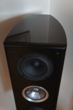
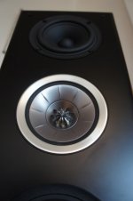
Rawson Repair Reflections

This thread is to share some details and reflections of Rawson built amps in need of repair.

I first signed up for DIYAudio when I was trying to fix hum in 2 Rawson Aleph J mini amps built by Rawson. After lots of reading, learning, and coaching I got those amps fixed up. Then I did Rawson repair for a friend on his amps. That lead to some F5 rebuilding, and then fresh builds of other amps here.

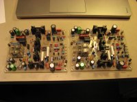
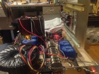
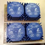
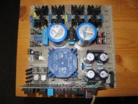
Here is an amp I'll be repairing -

The good:
• Aleph J circuit
• Gain, Bias, Offset measurements are operating to spec, great sound from amp
• Genuine Toshiba JFETs
• IRFP240 Mosfets
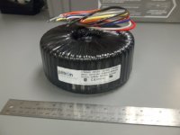
• Plitron 300VA 18+18V Transformer
• Dual Rail / Decoupled Stereo Configuration

The not-so-good:
• Grounding: No safety ground on AC Mains, no thermistor
• Poor quality PSU PCB build
• Single Rectifier Bridge / Center Tapped Transformer
• Loose Power Transformer
• Bulging PSU caps (about to fail)
• 2nd stage PSU caps rated at 25V (~5% from operating voltage)
• Transformer is buzzing/humming
• No bleeder resistors
• No A/C mains capacitor
• Wiring: orange for +, blue for -, blue for gnd, black lamp cord for speaker -. Blue and orange look great on Gulf livery Porsches, but not in PSU wiring...

• Single thermistor in the AC mains

What will get fixed:
• Add proper grounding
• New Dual Rail Decoupled Stereo PSU board - Jeff Young board
• Use 35V rated capacitors
• Go from center tap config to dual bridge using Schottky rectifiers
• Add power supply snubber circuit
• Add AC Mains Thermistors & 0.0033 A/C Line Cap
• Transformer - suggest swapping to Antek 3218 transformer
• Update aging electrolytic capacitors to Elna Silmic II’s
• Optional - add XLR's
• Proper wire coloring

Attachments

  • Modern Art PSU.jpg
    Modern Art PSU.jpg
    850 KB · Views: 1,368
  • Overview.jpg
    Overview.jpg
    914.6 KB · Views: 1,377
  • AC Mains.jpg
    AC Mains.jpg
    643.6 KB · Views: 1,315
  • Aleph Board.jpg
    Aleph Board.jpg
    745 KB · Views: 1,334
  • Aleph Gain Test.jpg
    Aleph Gain Test.jpg
    859.9 KB · Views: 1,330
  • Bulging Caps.jpg
    Bulging Caps.jpg
    608.2 KB · Views: 889
  • Plitron.jpg
    Plitron.jpg
    691.6 KB · Views: 881

DROP 02 - HeadPhone Amp - Help needed please

Greetings,
My DROP 02 Headphone Amp has no sound output. The red power light goes on. I inspected the board to see if any of the wires were loose, or any signs of caps burning etc. Everything looks fine. ( 2 photos attached).

I do not have the knowledge to test any f the components without help from someone. I really appreciate anyones input and help.

Much thanks,
Mike S

Attachments

  • 02 amp -2.jpg
    02 amp -2.jpg
    577 KB · Views: 124
  • 02 amp 1.jpg
    02 amp 1.jpg
    599.3 KB · Views: 114

Could you help design this Buffer?

I would like to make this circuit on stripboard. This is actually a buffer on the input in one of the Boss pedals, with some modification, so that the signal leaving the circuit is reduced with 50% in the end.

On the photo below, on the left side, you can see the original buffer circuit from Boss, on the right side it is the modified design (the blue circle is the transistor).

I wondered if someone could help me to convert it to stripboard design? I cannot do that myself, my knowledge is too little for that.

buffer2.jpg

Würth Elektronik ANP125 - Capacitors don’t cause any appreciable signal distortion

Würth Elektronik’s new Application Note ANP125 publishes the results of a study “The acoustic effects of harmonic distortion of aluminum electrolytic capacitors” on harmonic distortion of electrolytic capacitors. The result: Capacitors don’t cause any appreciable signal distortion.

The discussion is ongoing in the audio technology world about what circuit elements affect the sound quality of amplifiers. The app note by Würth Elektronik provides empirical evidence to add to this discussion and answers questions that most audio engineers have.

Application Note ANP125 is the result of international research collaboration between R&D teams at production sites in Asia and the Würth Elektronik Competence Center in Berlin. The text begins with an introduction to human hearing and psychoacoustics and goes on to examine harmonic distortions in capacitors. Furthermore, results from model calculations are presented in order to check the plausibility of the measured results. The measurements show no appreciable distortion of signals caused by capacitors.

Material variations also tested

Dr. René Kalbitz, Product Manager in the Capacitors & Resistors Division at Würth Elektronik eiSos and author of the study, explains:

- The investigations indicate that material variations have a negligible influence on distortions, and these are below the hearing threshold. Electrolytic capacitors do not add any appreciable harmonics to the fundamental frequencies in signal transmission, so, to a good approximation, they can be considered as linear components. It is likely that other voltage-independent capacitor types and passive components, as a rule, generate similarly low distortion amplitudes compared to the audibility threshold. Consequently, the choice of non-linear components such as operational amplifiers and diodes has a greater distortion impact on the audio quality of the amplifier, i.e., the overall distortion characteristics, than the choice of electrolytic capacitor.

ANP125

LM4702 meets the Pioneer SX-838

The first "stereo" I purchased (as opposed to "built" or "received as a hand-me-down") was this Pioneer SX-838 -- I bought it used at Harvey Electronics on 45th Street and lugged it back to the apartment in Brooklyn Heights -- circa 1976. Still has one of the nicest FM receivers I own -- but the protection circuitry went wonky and the device would blow output devices all the time. If you can't find one of these receivers in the junk yard you can buy one on the Bay for about $30.

Turns out that the printed circuit boards I had burned for the LM4702 fit almost perfectly onto the heatsink for the Pioneer SX-838. I had to put the HS on the mill and grind down one of the fins a bit so that the spacers would fit:

An externally hosted image should be here but it was not working when we last tested it.


Here's the original output board and its location:

An externally hosted image should be here but it was not working when we last tested it.


The LM4702 Board mounted on HS:

An externally hosted image should be here but it was not working when we last tested it.

Should I build a better box?

I can build better boxes, with better bracing than I usually do. I've been trying to make a good center channel speaker. Mine are sealed vertical two or three ways typically. Right now I'm working with 2-ways.

I had a leftover box I was reusing. Roughly a 9 x 12 baffle, and about 9 deep. Woofer is 6.5". Box is unbraced 3/4" MDF, and 3/4" baffle. I like little speakers for some things. I Made a new x-over at 3k. The response looked fine. After several days of use, I was going to assemble the x-over, and call it done. I removed the speaker from the system. I wanted to watch some shows on my HT system. I replaced the center with one of my mains. It made a better center than the one I was going to finalize. Now I want to figure out why one sounds better than the other.

The issue is in the low vocal range. A coloration I think. The vocals sounded muddy. I previously thought the problem was the movie soundtrack, but this speaker handled it really well. Other movies seemed good with either speaker. Can lack of box bracing make that big of a difference?

Both speakers are sealed, and the Q is low. Both were crossed to a sub at 60 or 80hz, I think. Their f3s are a little different. Both in the 80 to 100hz range. Drivers are pretty low in distortion, and this problem was not at a loud SPL It was dialog. The movie was Midway, which is on Netflix.

I have REW, and can measure response at the seat, and compare. I don't expect to see any drastic difference though. What else might show the box issue, if that's the cause?

Building with the Soekris dam1121

This thread is for everybody to share designs, ideas and tips for building DAC's using the Soekris dam1121 R-2R Sign Magnitude DAC module.

The module is intended to be mounted with component side down on a main board with power supply, digital audio receivers and with the user interface. It can also easily be used with cabling, but note that the headers are 2mm pitch.

I have no plans to make main boards to carry the dam1121 module, but will be happy to assist anybody who want to make one, plenty of opportunities to make different ones, from simple stereo ones to high end balanced ones and with different buffer technology.

Info to start with:

The dam1121 product page, with a manual and example schematics for a balanced test board: www.soekris.dk/dam1121.html

Gizmo to record digital (spdif) to USB stick

Is there a device that can record digital spdif to a USB stick?

I listen to Internet radio via a Cyrus Stream, the output going to a DAC either via optical or electrical signal spdif. I'd like to record in .flac format onto a USB memory stick ideally to have files named (artist, song name).

I have a CD recorer, a HD audio recorder, which should be able to record the music but I'm not sure if the song names are saved. Lastly I also have an MD recorder but that records. MP3 as ATRAC which is lossy compression so less than ideal.

Who RePaints and Stencils the Front Panel of Audio Components ?

I have been ready to do a total restoration of my classic Preamp and Amplifier. Does anyone know who I can contact to restore the FRONT PANELS with new stenciling
as like the original lettering ?

I have seen many replacement panels for various audio pieces and they are perfect but I have no-clue as to what business would do this.

Sincere thanks to anyone who can steer me in th eright direction.

Mike S>

Has anybody tried a LPS just for the opamps used with TPA3255?

I wonder if someone has tried a LPS with its own linear regulator to be used to power the Opamps at the input of a tpa3255 board ?

Continuing my tpa3255 amplifier building, the sound is very good as it is, but I guess it can be even better ?

The op amps I use is two opa1612 . The power supply for both opamps on the board, uses a xl7015 regulator with DC from a 36V 6A smps power brick. The DC power for the opamps is 12V.

Looking at the pin configuration, it seems like pin four and eight is for -V and +V .
Can this mod be done by simply cutting the two pin-legs on the IC adaptor ( dissabling -V and +V ) , then soldering two cables to the -V and +V points marker in red on the picture ,and use a linear supply with lm317 I have ?

Is it a safe mod to do this ( I hope no common signal ground at pin 4 ? ) .

Is there audible differences for the better to try driving the opamps with linear regulators ? Whats your experience ?

IMG_0841.jpeg


IMG_5574.jpeg

New member learning the audio repair hobby

Hello DIYAudio community, thanks for letting me join! I have been restoring vintage stereos for a couple of years now (Marantz, Sansui, Pioneer, Mcintosh) and excited to learn more about stereo design and repair. I have been buying, restoring and reselling stuff just as time and money allows as a hobby in addition to my regular full-time job. Looking forward to reading the forums and sharing information with the group!

A Humble Music Enthusiast

Hello everyone. i am a music enthusiast who loves mostly analog audio and equipment. i own a pair of turntables and a few old amps . i have a decent collection of vinyl's and CD's.. i love listening to almost all genre of music except a few variants of new age music which i cannot comprehend to . love the music of the 80's and 90's .. very few new songs make it to my playlist.. love playing physical media rather than streaming. i love to do DIY though i am not well versed in electronics theory. i mostly do amps from DIY kits and be happy with it.. Thankyou for having me here.

Introduction from The Dark Nak

Hi everyone,
I am new to this forum with absolutely no knowladge in maintaining Nakamichi CD players although I am not too bad in renovating their cassette decks. I came here to find some teacher to help me to maintain my Nakamichi CD player MB-2, MB-1S and MB-4S. I am particulatrly interest in the test unit to calibrate these CD players. Thanks for reading.

P3A-More upgrades

Sorry this one will be kinda long ....

Most of you know that i work with the P3A more than 5 years now i end up changing minor things that had quiet serious effects on it .Meaning of the post is that i am looking for more suggestions for the best but without changing the original concept of the P3A .

Dear Friend Wahab suggested to remove the bootstrap and make it a ccs but this will alter the character of the P3A and on the other side i like the bootstrap so this type of changes is not my go .


bellow i will summarize and comment the changes ive made in categories and wait for your comments and suggestions .


LTP
for the LTP all my PCB feature thermal junction that is better for stability and offset,then always semis are chosen for high hfe over 400 and closely matched improved and made the bass more tight and generally improved the all amplifier by far . also tried to choose semis from a trusted manufacturer and also use semis that have lower voltage than BC 546 to force them work on the edge . Also played with LTP current +- a few ma with good results .

FILTER-MILLER CAPS
for filter and miller caps i try to use best of quality styroflex for the input and silvermica 500V 2% for VAS and driver depending on the choice of VAS semi i have lowered the values low as 68 pf with no obvious stability issues but with some sonic difference for the best. install a DC input and skip input cap when its possible to do .

VBE multiplier
It seems that after i common heatsink both of the drivers and in the middle attached the VBE transistor i ve noticed that the amp become much more stable and sound was far better and in a better "order " i have added 0.1mfd as a bias stabilizer ....

VAS /DRIVERS
been trying many excluded from the process MJE series since sounded worst eventhough pretty rugged device, and realized that this process is seriously related to the choice of outputs ....For the record the best combination ever was the BD829-830 paired with 2SA1302-2SC3281...BD 139-140 with 2SA1943-2SC5200... obviously different combinations will produce different sonic signature.

These are in a nut shell the small changes i ve made and most of my P3A run at no more than 40+40 volts and with 60.000 mfd for 2ch amplifier as about the bias always depending on the choice of semis an optimum 70-120ma is the best while tests ive made to 250ma didn't improve much and actually i think made the amp worst .

--------------------------------------------------------------------------------------------------------------------------------------------------------------------------

As many know i am in the repair business so many of my costumers often take a P3A amplifier as a replacement amplifier from my shop while their amplifier is under repair ...At 99% of the cases the costumer will call the office in order to know more about the amp since he is thrilled with sound and even express the intention to buy one .

For the record i will state the type/brand of amplifiers that the P3A kicked *** off at least according to the costumer
---Plenty of Musical Fidelity
---Plenty of AUDIOLAB
---Few Goldmund
---Plenty Of QUAD
---One ADCOM
---2 NVA amplifiers
---Few Rotels
---Few Hardman Cardon


Changes that produced bad results


---High bias 250ma i think made the amp stiff and slow
---High rail voltage 52+52 volts produced more power and heat, some stability issues But no sonic improvement ...

---been thinking to make the all thing run from a regulated power supply but i am not sure if this will change anything for the best

---Been thinking to separate output from drive circuit in order to supply input circuits from other regulated voltage probably higher but never done that yet

---Been trying very fast drivers with relatively slow outputs with bad results

---Been trying the opposite like normal drivers but with very fast outputs

now suggestions please ppl !!!

kind regards
sakis

(Thanks for your time )

trouble with Denon POA 2800 amp - Anatech RSVP

I have owned this amp new since 1998 and have enjoyed it's powerful
sound delivery, through my B&W P6, w/o fault until 10/2006.
Back in Oct/2006 my right channel failed.
I dropped same off to Denon Repair in Markham and, now after three
subsequent repair attempts, I am still confronted w/ no sound from Right Channel.
Following first repair - sound kicked in, until I shut system off and tried to restart
the following day - NO RIGHT CHANNEL
Same thing occurred following 2nd repair attempt, and finally on third repair
attempt - NO RIGHT CHANNEL at all.
Completed neophyte testing - alternating speaker wires, followed by
alternating output chords from pre-amp, to support fault is related to RC
of power amp.
Any ideas - I believe I read somewhere that a breach in solder connection
can show up once system heats up ( expansion occurs ) ?
Please help as my IPOD player is no match for my wonderful Denon/B&W system.

THANK YOU

A Directory of Apex Audio Amplifiers

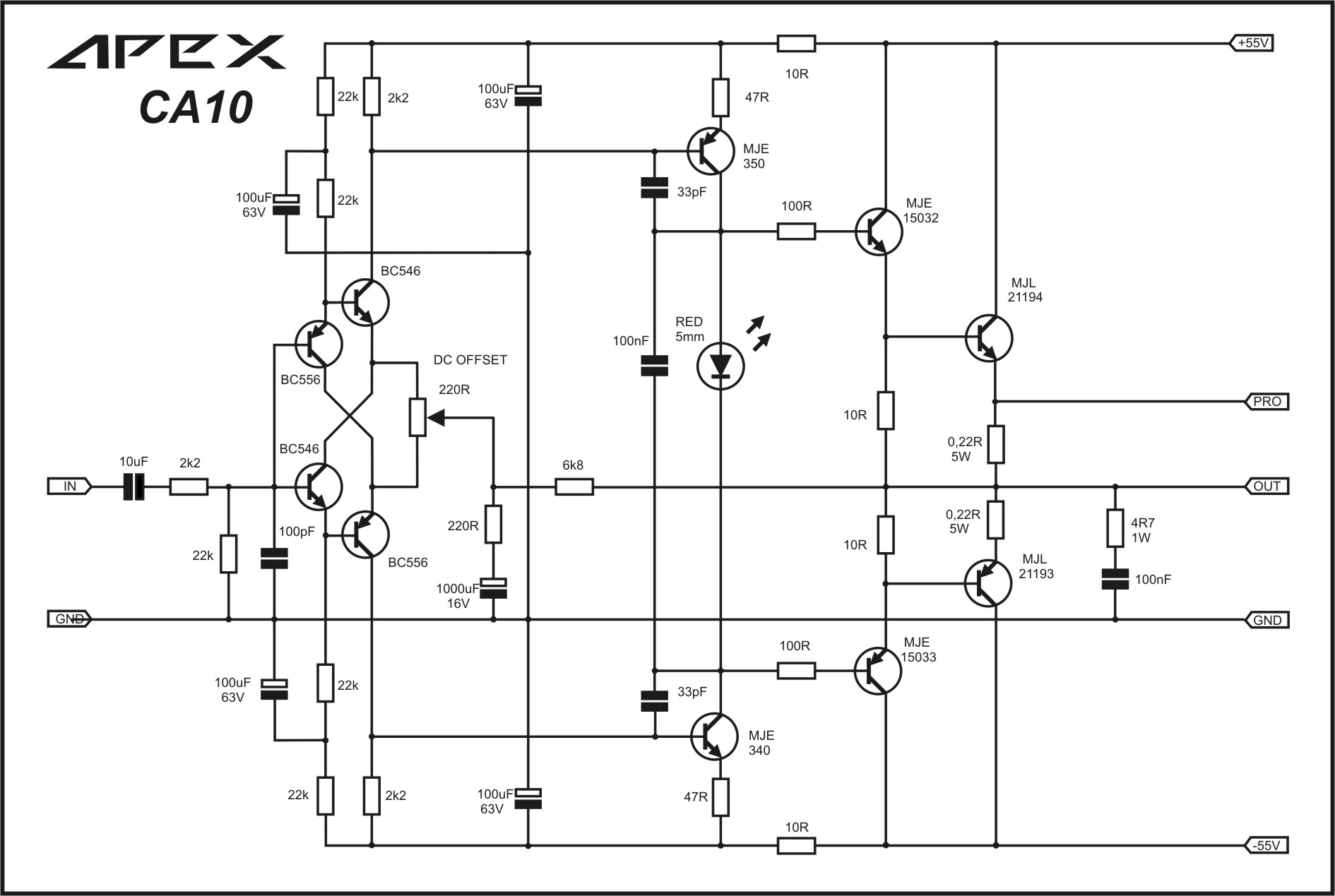
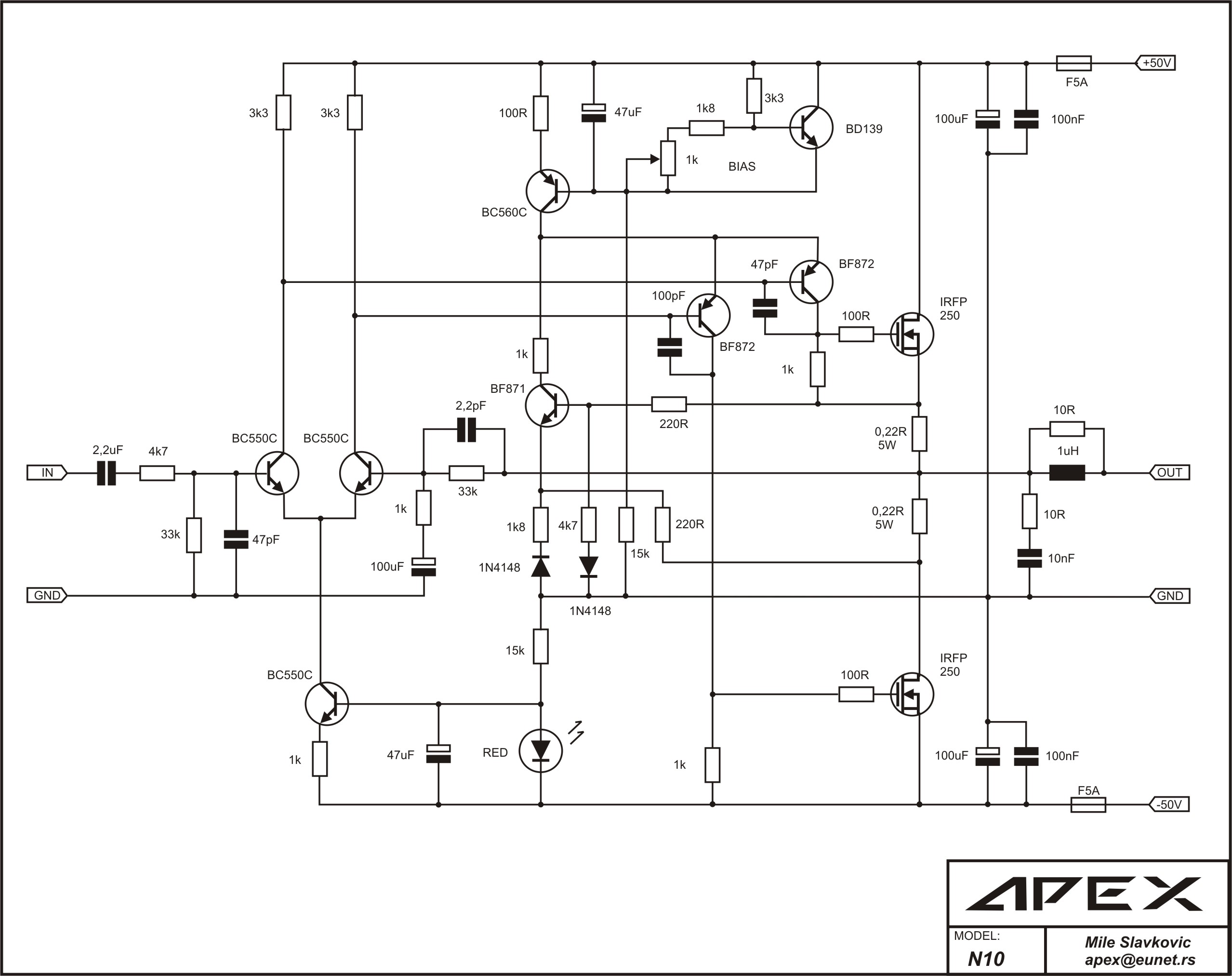
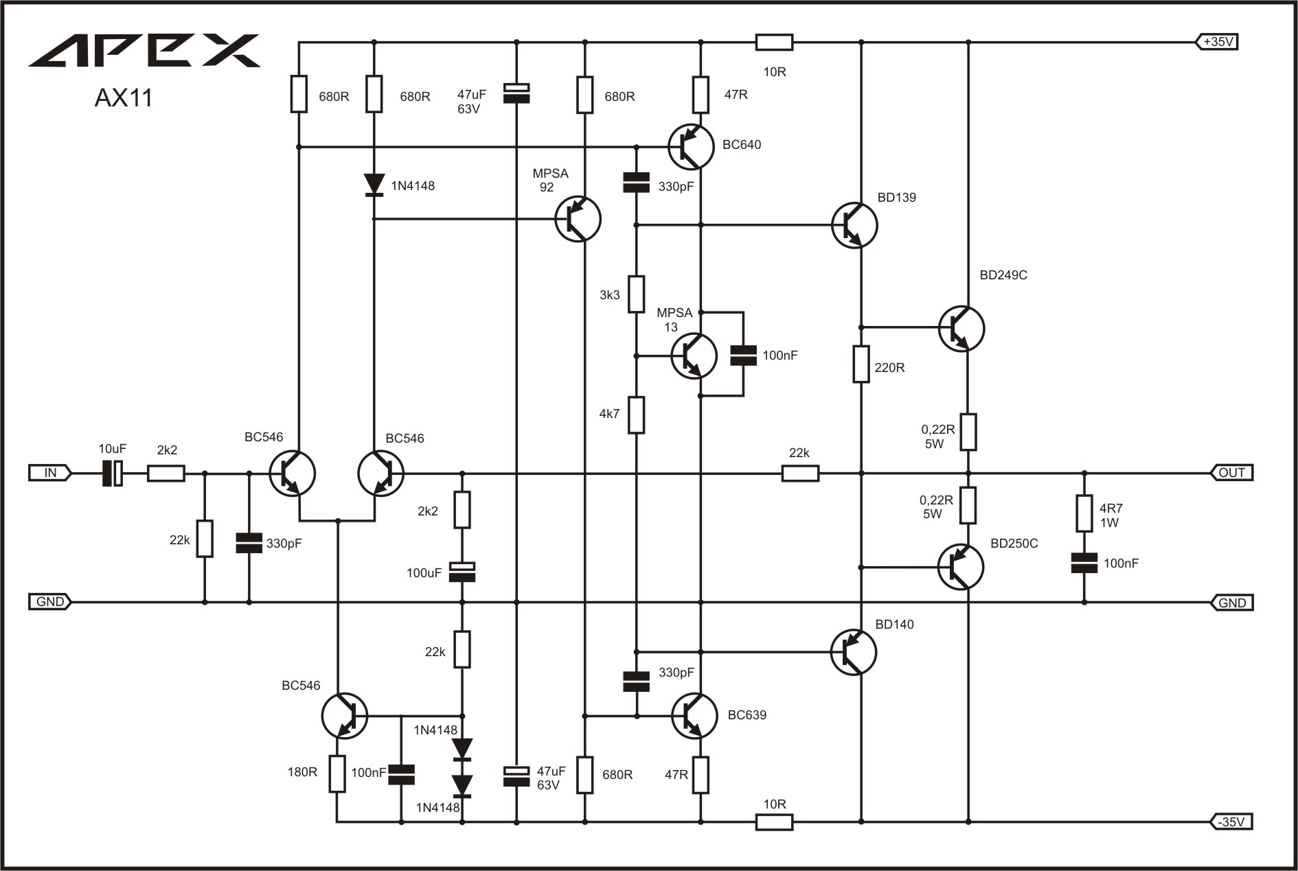
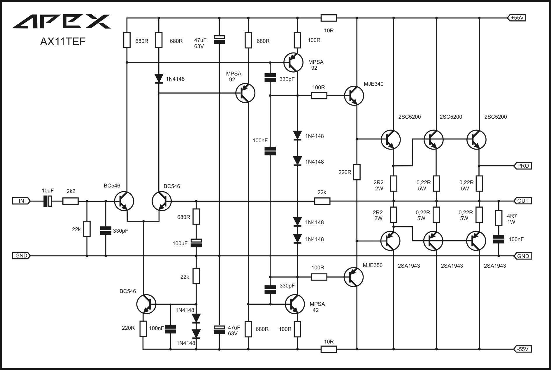
This thread is a consolidation of the numerous amplifier designs that member Apex Audio has generously provided the DIYA community over the past several years. The designs mostly come from the enormously popular (and large) thread 100W Ultimate Fidelity Amplifier - diyAudio which has become a bit unwieldy to use as a reference for designs. It is my hope that this thread will become a repository for Apex Audio's amplifier designs that is in an easily usable and searchable format. There are also several threads by Apex that have PA amps, etc - please consider providing links to those amps as well.

Note: click "Reload" page on your browser to auto scale the rather large image schematics. These are the original images as posted by Apex Audio. I only point to them.


To start things off, I have included below an initial list of amp designs that I could find using the search feature (I simply did a search for "AXn" where n is an integer representing the number of active devices). The problem is, there are amps named FXn, Bxn, An, Bn, ANn, etc. So it would be helpful if other members can point out designs that need to be added by posting here. From time to time, I will go in and update Post #1 to be an index pointing to the locations where the PCB layouts are located, the BOM, photos of working examples, etc.

When posting a suggestion for me to add to the index, please include the following in this order of importance:

1. Name of the amp, ie,, "AX11TEF" and rated watts and a note if special application like (uses lateral FETs or is fully-symmetric, etc)

2. An image of the schematic as drawn by Apex Audio (link to the image is fine), or if the amp is a mod by another member, a link to the member's schematic. Such as the FX8 Bimo Mod...

3. A link to the post or location where the amp design is discussed (either first mentioned or a key development where a working design is produced).

4. A link to the PCB layout sprint file or Gerber files if available

5. A link to the LTSpice/Multisim/TINA simulation file if available

6. A link to a photo of an actual amp that has been reduced to practice

7. A link to measured performance (FFT distortion plots, O-scope traces, etc.)

Thanks in advance for contributing to this index, and I hope you all find it helpful.

Finally, a huge thanks to Apex Audio for his tireless creativity and help in giving us so many great sounding designs to play with. :cheers:

Regards,
xrk971

Update June 20,2016: Miro provided a nice table of 68 schematics here A Directory of Apex Audio Amplifiers - Page 5 - diyAudio


Here is what I have so far for the Index. I will add links to the above items as time permits and as people provide feedback.

#### AN INDEX OF APEX AUDIO AMPLIFIERS ####

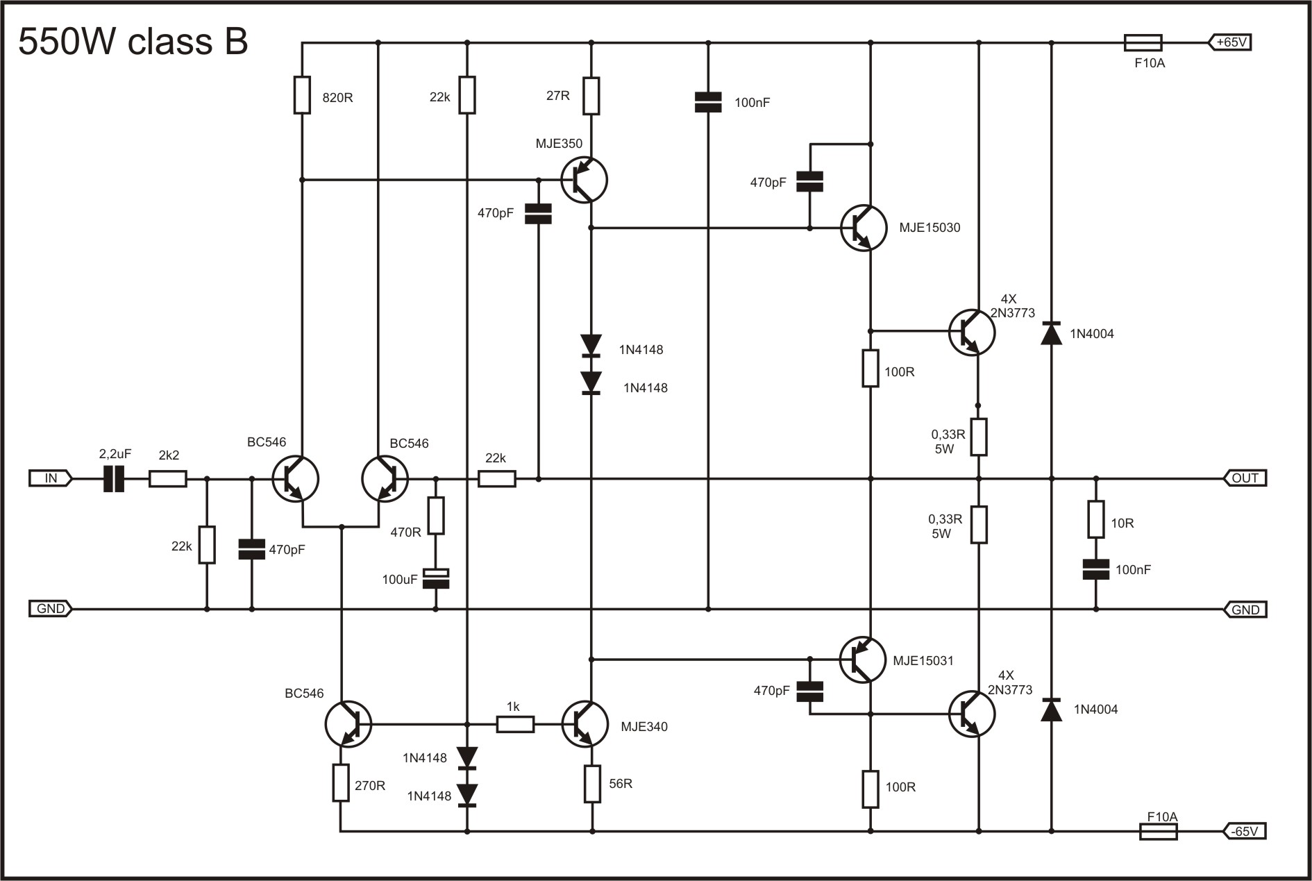
Quasi for Beginners - added Aug 6, 2016:
172638d1274698453-quasi-amplifier-beginners-apex-550w-classb.jpg


QUASI Amplifier for Beginners - diyAudio

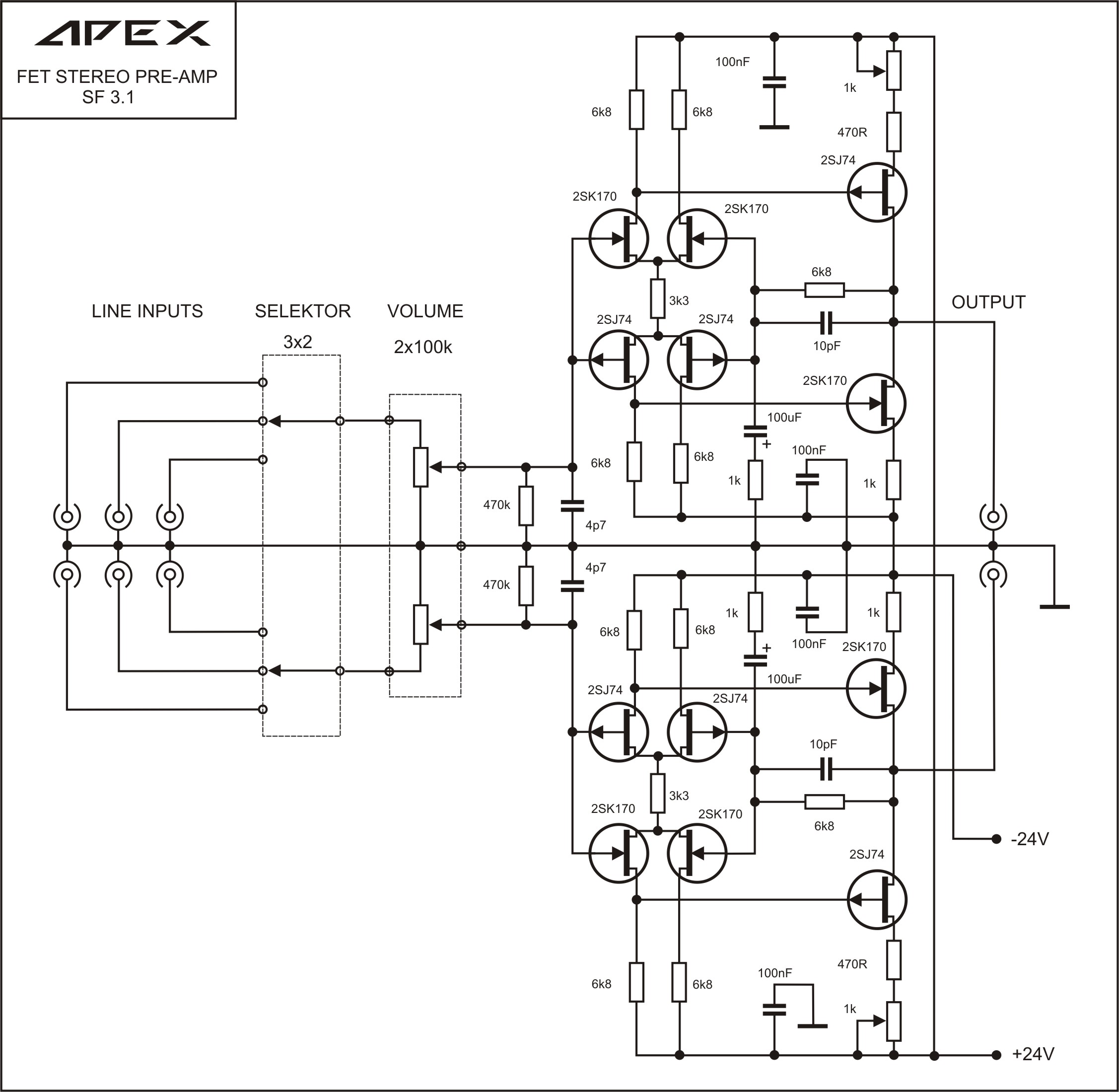
SF3.1 AllFET preamp 470k input impedance - added 7/14/2016:

100W Ultimate Fidelity Amplifier

165430d1270331111-100w-ultimate-fidelity-amplifier-apex-fet-preamp.jpg


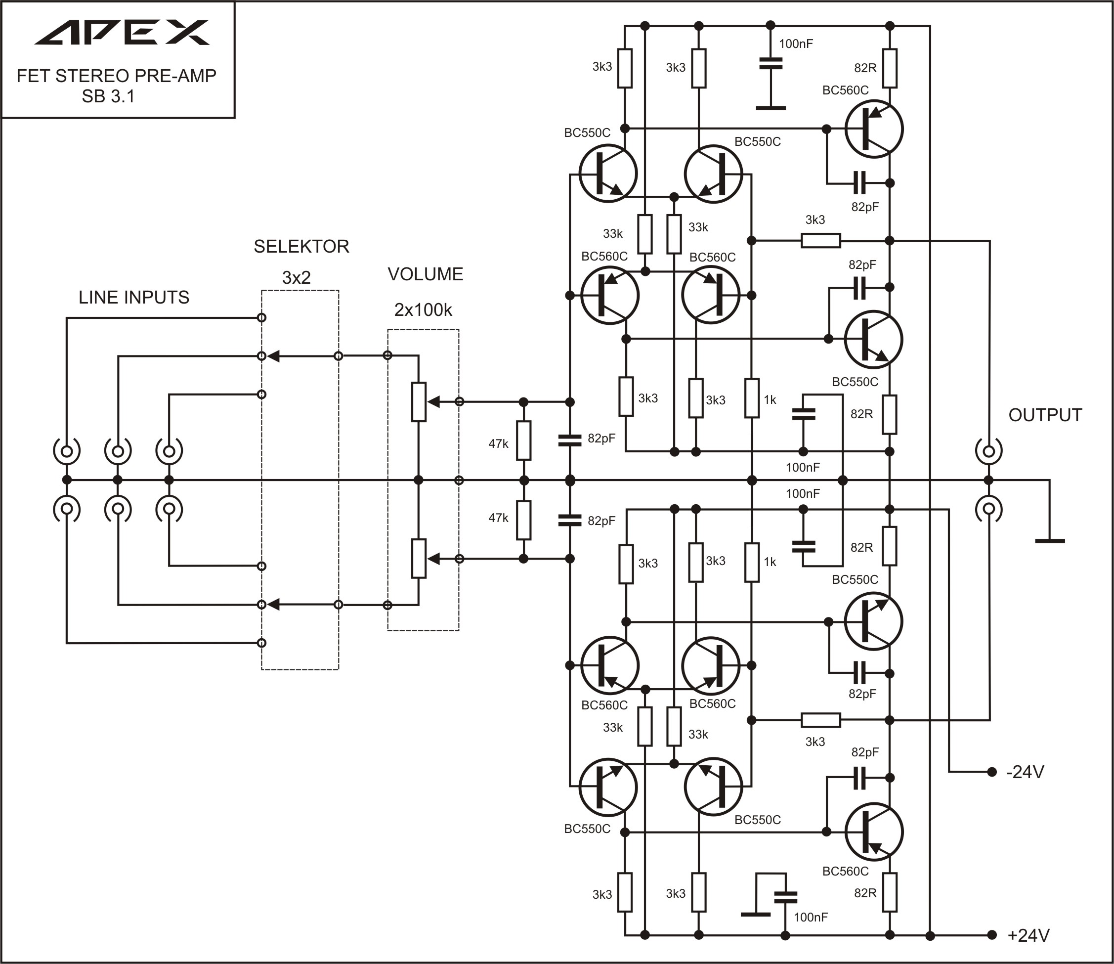
SB3.1 BJT preamp 47k input impedance - added 7/14/2016:

100W Ultimate Fidelity Amplifier

165433d1270333407-100w-ultimate-fidelity-amplifier-apex-bjt-preamp.jpg


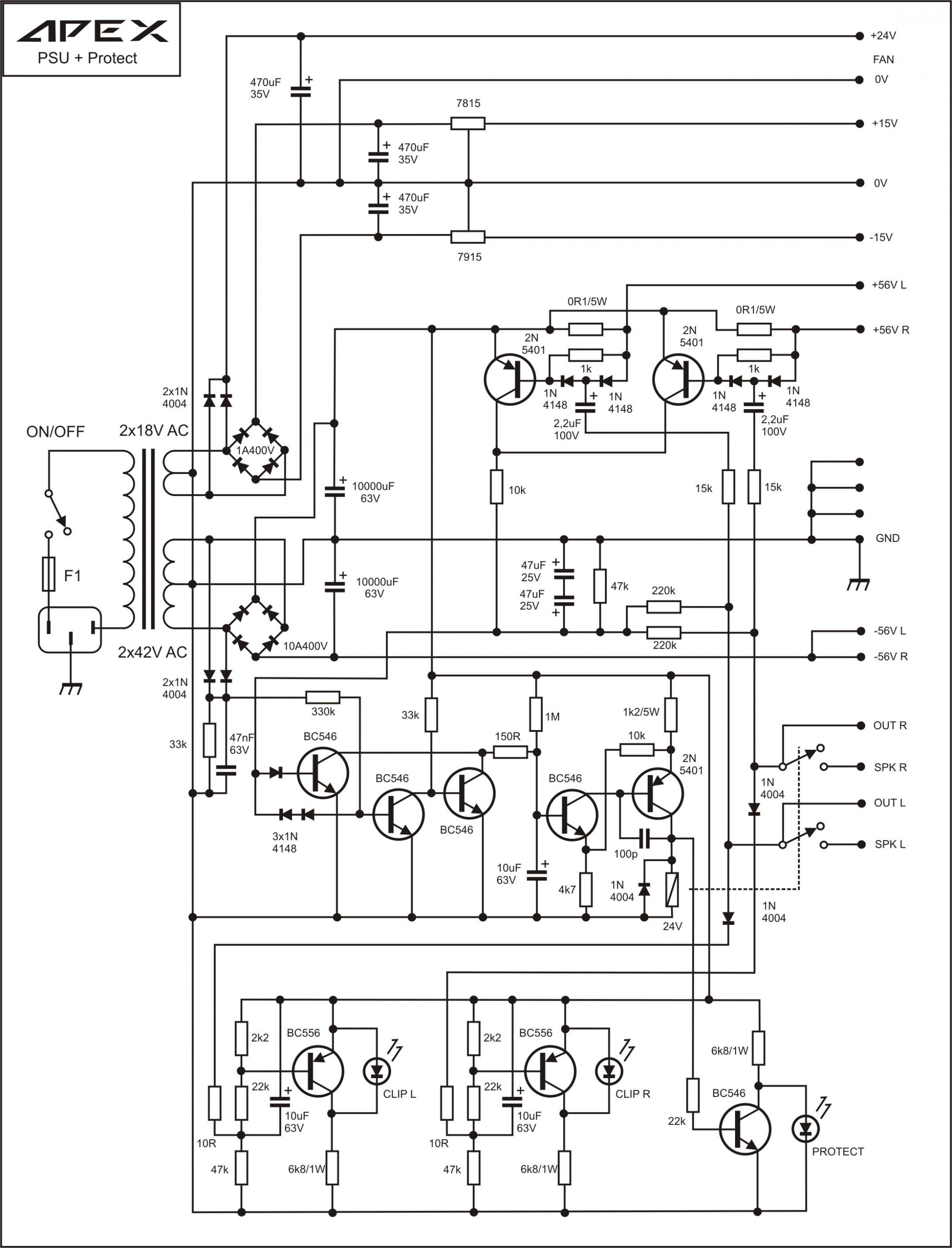
PSU + Protect - added 7/14/2016:
166975d1271268112-100w-ultimate-fidelity-amplifier-apex-psu-dc-protect.jpg


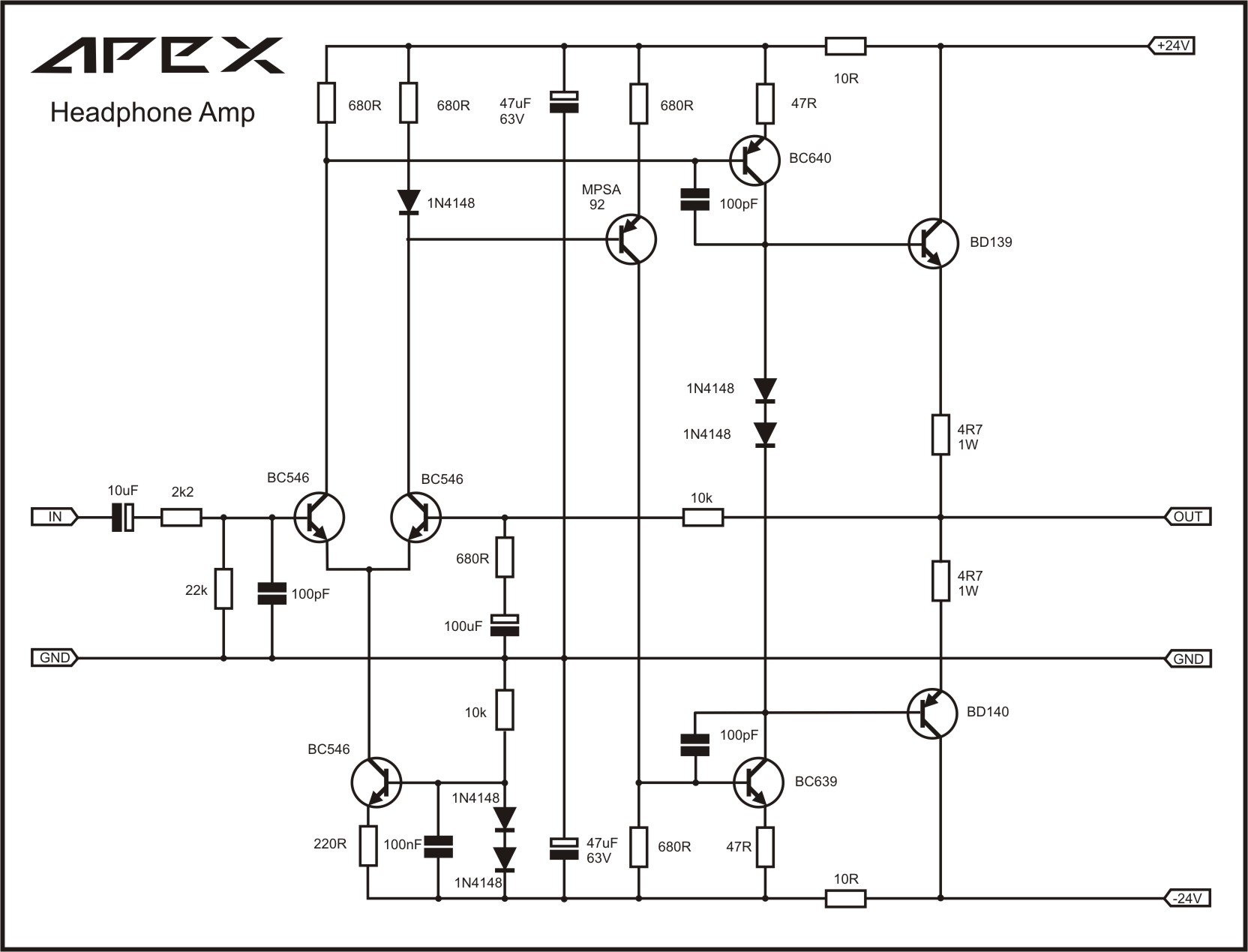
Headphone Amp - added 7/10/2016:
542316d1460041518-100w-ultimate-fidelity-amplifier-apex-headphone-amplifier.jpg


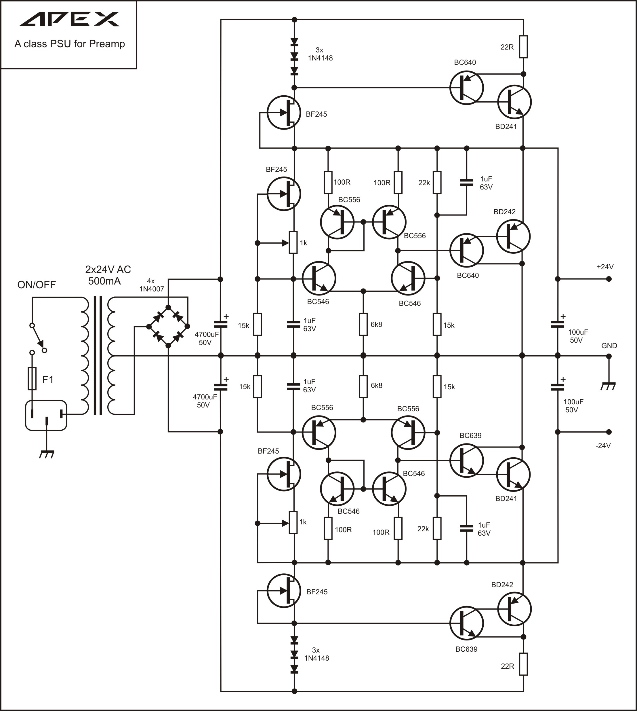
Class A preamp power supply 24v - added 7/8/2016:
http://www.diyaudio.com/forums/power-supplies/164365-class-preamp-psu.html#post2140391

165267d1270226399-class-preamp-psu-apex-2x24v-aclass-psu.jpg


PDF transfers:
http://www.diyaudio.com/forums/soli...imate-fidelity-amplifier-791.html#post4768785

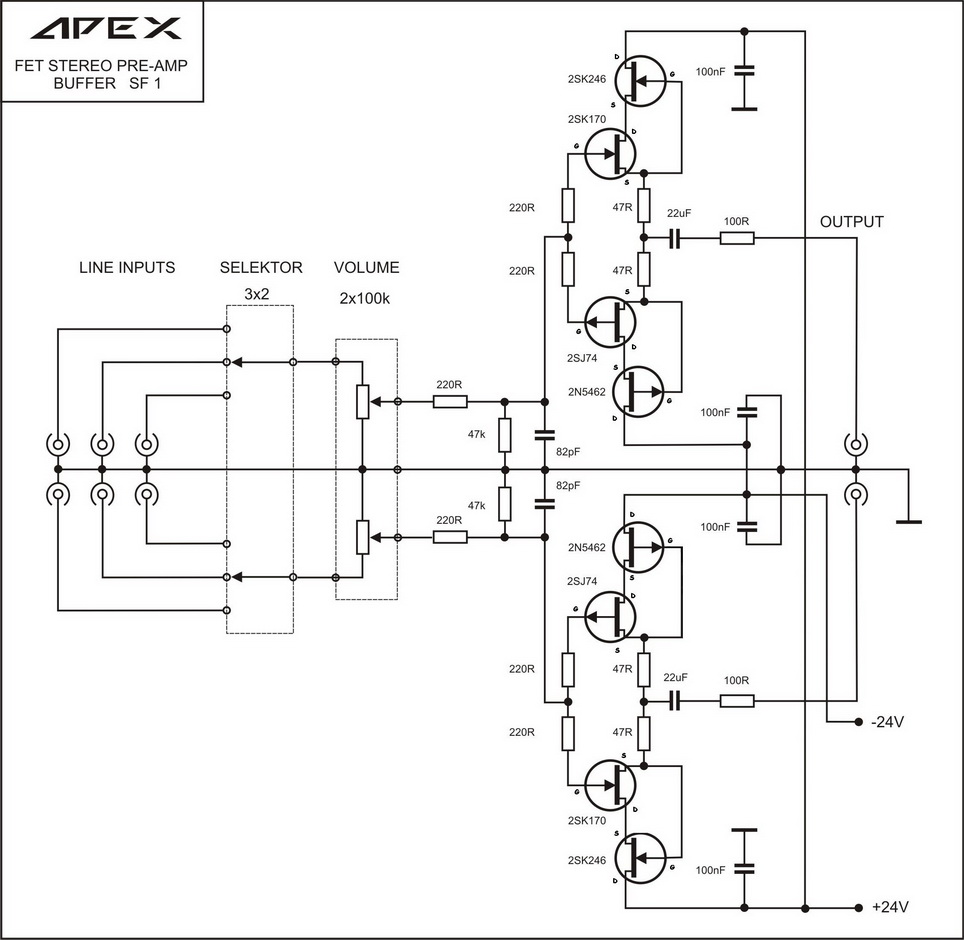
SF1 all FET buffer - added 7/7/2016:
http://www.diyaudio.com/forums/solid-state/173462-studio-reference-amplifier-33.html#post2596440

226001d1307363032-studio-reference-amplifier-apex-fet-preamp-buffer.jpg


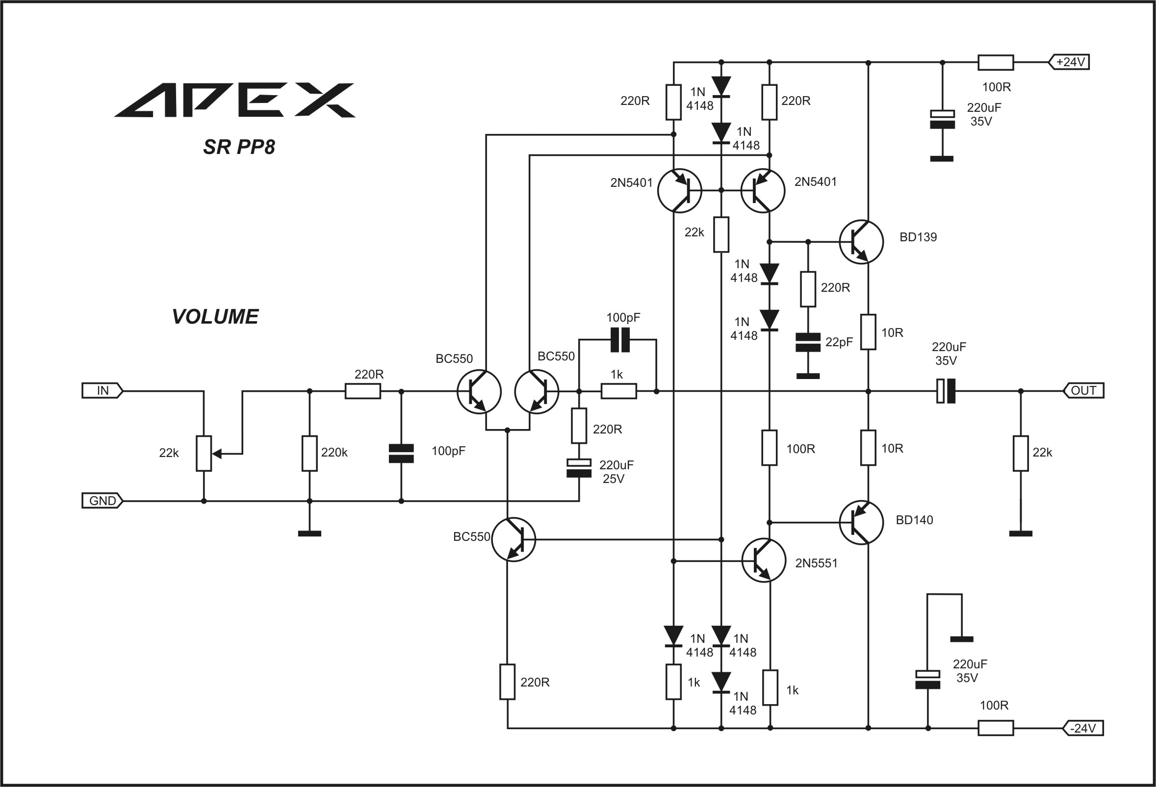
PP8 SR Preamp - added 7/7/2016:
http://www.diyaudio.com/forums/solid-state/173462-studio-reference-amplifier-178.html#post4180772

458406d1420900146-studio-reference-amplifier-apex-sr-preamp.jpg


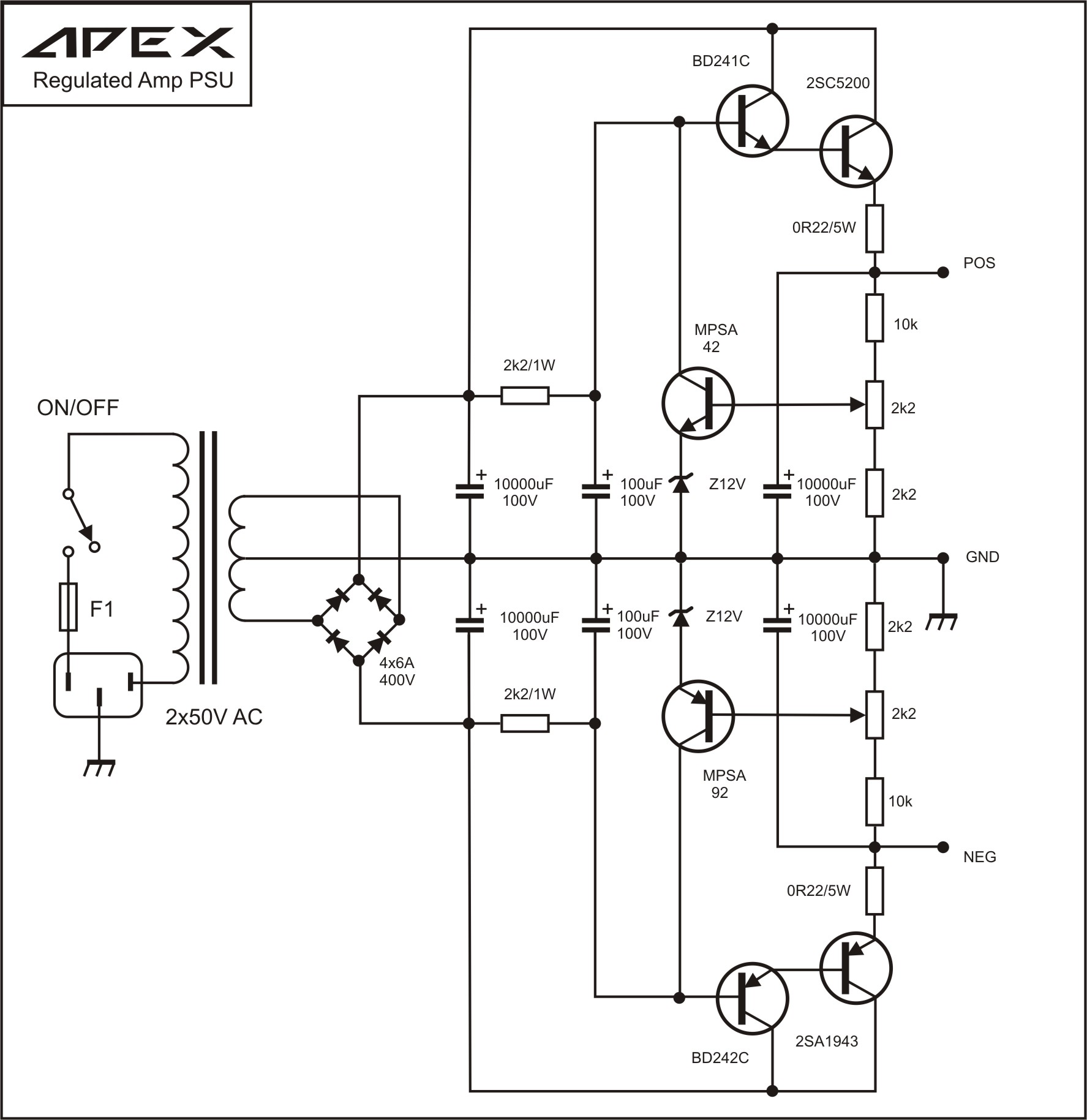
Regulated PSU, output voltage with this PSU can be set from 35V to 65V 5A with single pair 2SA1943/2SC5200 - added 6/29/2016:
188157d1284671254-studio-reference-amplifier-apex-regulated-psu.jpg


PCB: http://www.diyaudio.com/forums/solid-state/173462-studio-reference-amplifier-2.html#post2305489

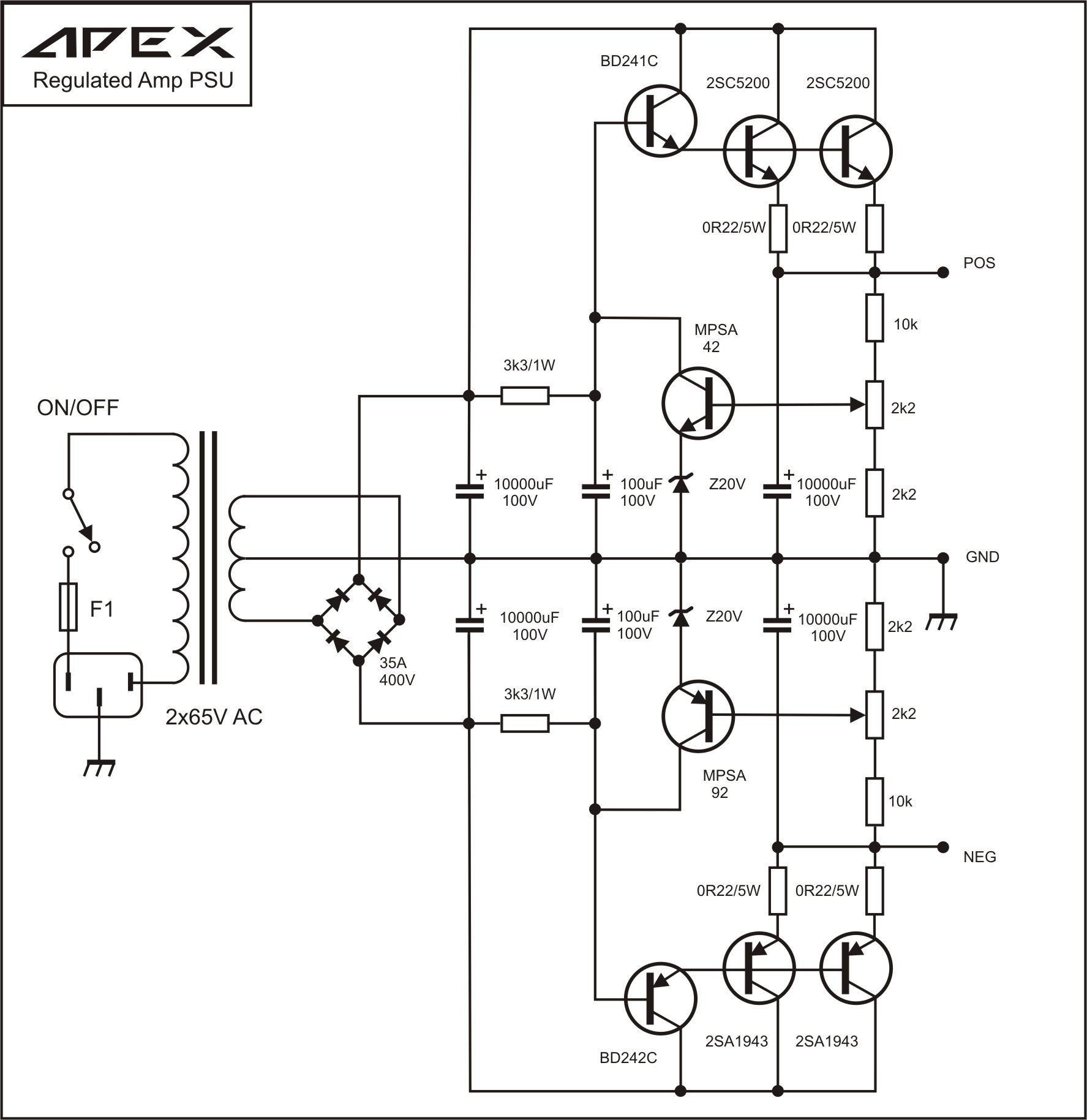
4 Output version for 55v to 90v rails:
188172d1284677123-studio-reference-amplifier-apex-regulated-psu-10.jpg


More info (post #6):
http://www.diyaudio.com/forums/solid-state/173462-studio-reference-amplifier.html

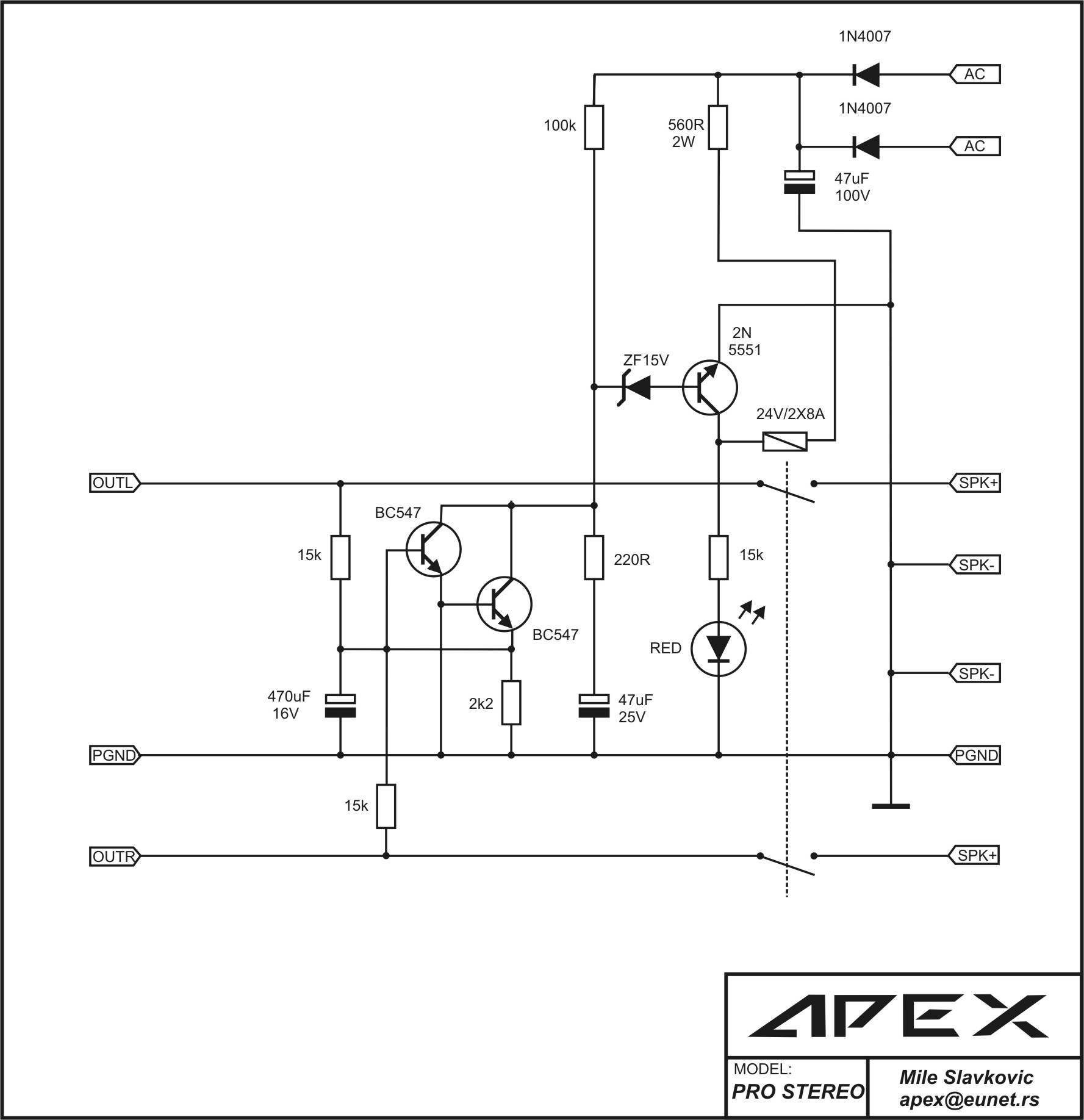
Simple Stereo Protect - added 6/22/2016:
457759d1420567023-100w-ultimate-fidelity-amplifier-apex-simple-protect.jpg


PCB:
http://www.diyaudio.com/forums/soli...imate-fidelity-amplifier-406.html#post4176074

A3 - added 7/12/2016:
An externally hosted image should be here but it was not working when we last tested it.


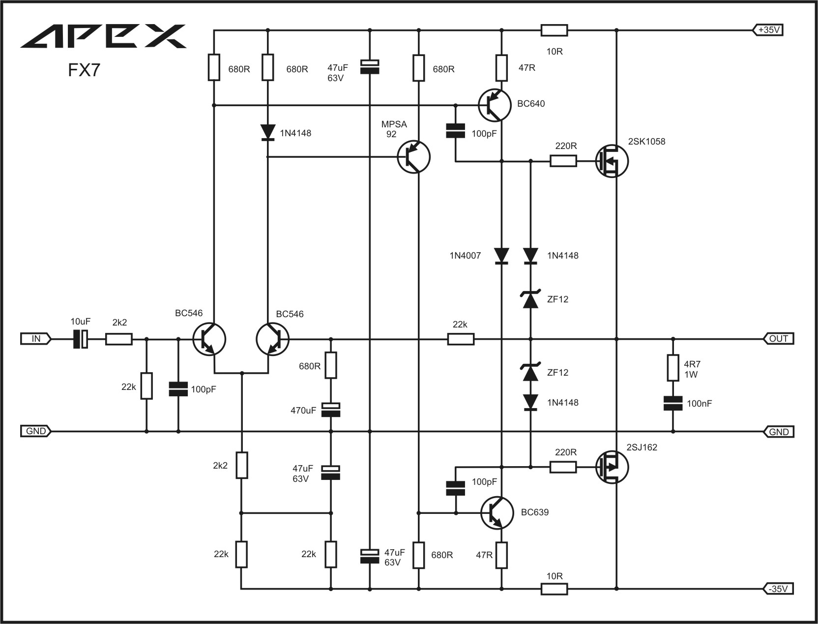
FX7 - added 8/11/2016:
545562d1461618484-100w-ultimate-fidelity-amplifier-apex-fx7-sch.jpg


100W Ultimate Fidelity Amplifier

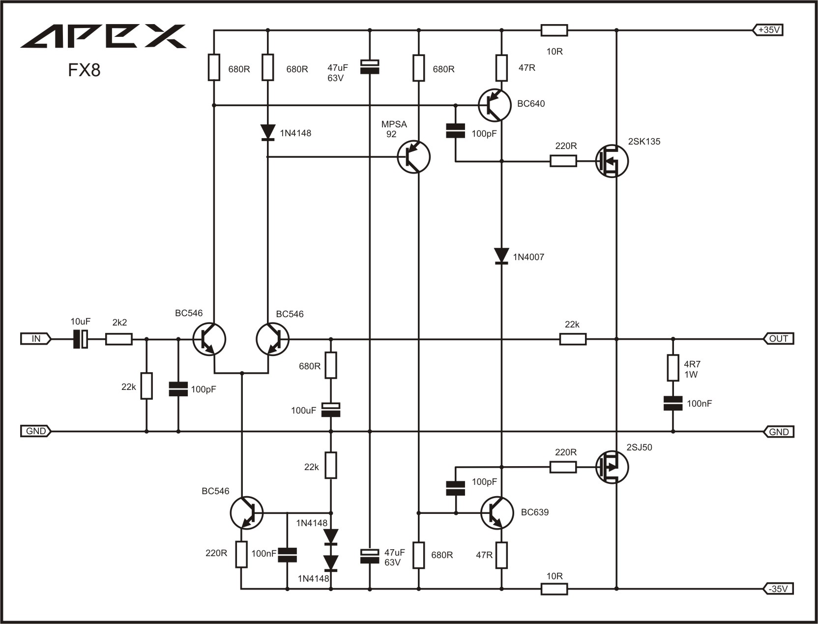
FX8 (50w) - uses lateral FETs:
347359d1367965695-100w-ultimate-fidelity-amplifier-apex-fx8sch.jpg


(FX8 links provided by Jeshi on 6/2/2016)
50watt, NPN differential input, complementary NPN/PNP VAS, lateral MOSFET output.
APEX FX8 post 2125, APEX layout post 6174
Prasi initial PCB layout post 6160, Prasi/Sonal edited layout post 6184
Bimo-mod version with simulation post 6483 using 2SC1845 input, 2SA1381/2SC3503 VAS, 2SK1058/2SJ162 output.
Prasi layout of bimo-mod post 7146
FX8 Bimo mod build with speaker test results:
http://www.diyaudio.com/forums/soli...imate-fidelity-amplifier-775.html#post4755887

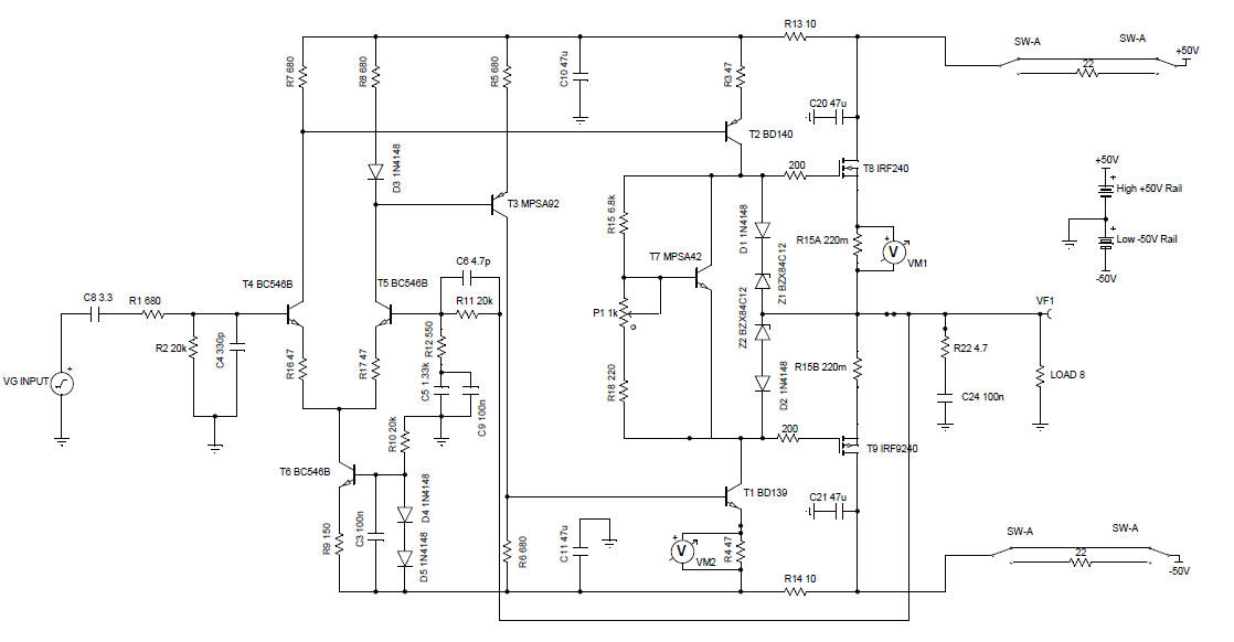
FH9 (50w) - xrk971 mod for vertical FETs:

http://www.diyaudio.com/forums/solid-state/292226-directory-apex-audio-amplifiers.html#post4733400

Edit March 31, 2020: Updated Gerbers with solder pads on both sides here:
100W Ultimate Fidelity Amplifier

550019d1463581537-100w-ultimate-fidelity-amplifier-fx8-xrk971-hexfet-vbe-schematic-v2.png


Tina Sim, Sprint and Gerbers:
http://www.diyaudio.com/forums/soli...imate-fidelity-amplifier-746.html#post4718255

PDF's:
http://www.diyaudio.com/forums/atta...e-fidelity-amplifier-fh9-ver1.04-top-view.pdf

http://www.diyaudio.com/forums/atta...ier-fh9-ver1.04-toner-transfer-silkscreen.pdf

http://www.diyaudio.com/forums/atta...er-fh9-ver1.04-toner-transfer-copper-side.pdf

BOM:
http://www.diyaudio.com/forums/soli...imate-fidelity-amplifier-799.html#post4774271


FH9 fully built and tested by xrk971 using Sonal Kunal's Gerber files:
http://www.diyaudio.com/forums/soli...imate-fidelity-amplifier-784.html#post4764003

Note that I substituted 20k for 22k and 550R for 680R for resistors as shown in silkscreen. Also, final version uses BD139 as Vbe multiplier rather than MPSA42 as shown in Tina diagram.

FH9 HV - 120w (8R) output single pair vertical hexFET amp (requires swapping BD139/140's for KSC3503/KSA1381's):
http://www.diyaudio.com/forums/soli...imate-fidelity-amplifier-790.html#post4768191

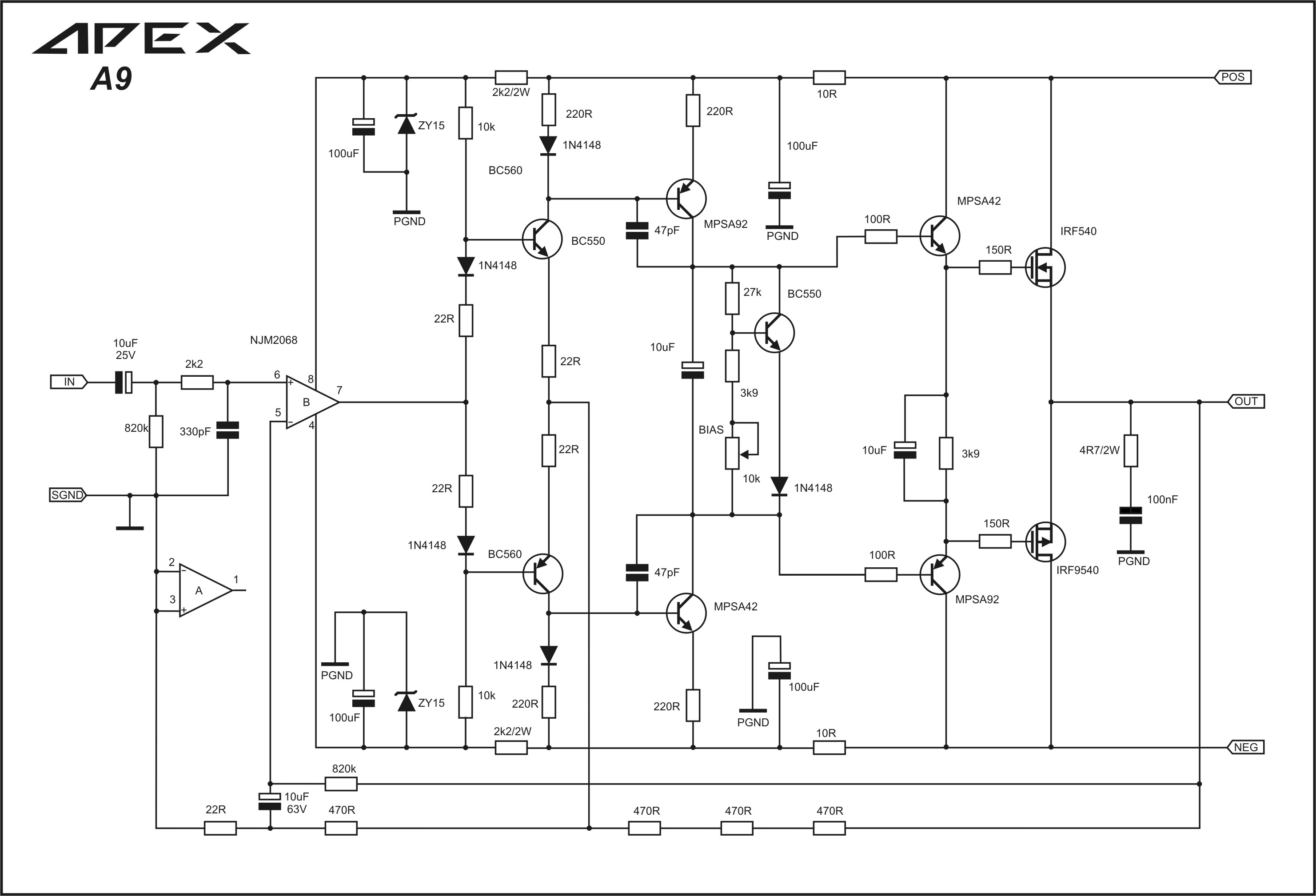
A9 CFA:
449041d1416219044-100w-ultimate-fidelity-amplifier-apex-a9sch.jpg


PCB pdf:
http://www.diyaudio.com/forums/soli...imate-fidelity-amplifier-357.html#post4133456

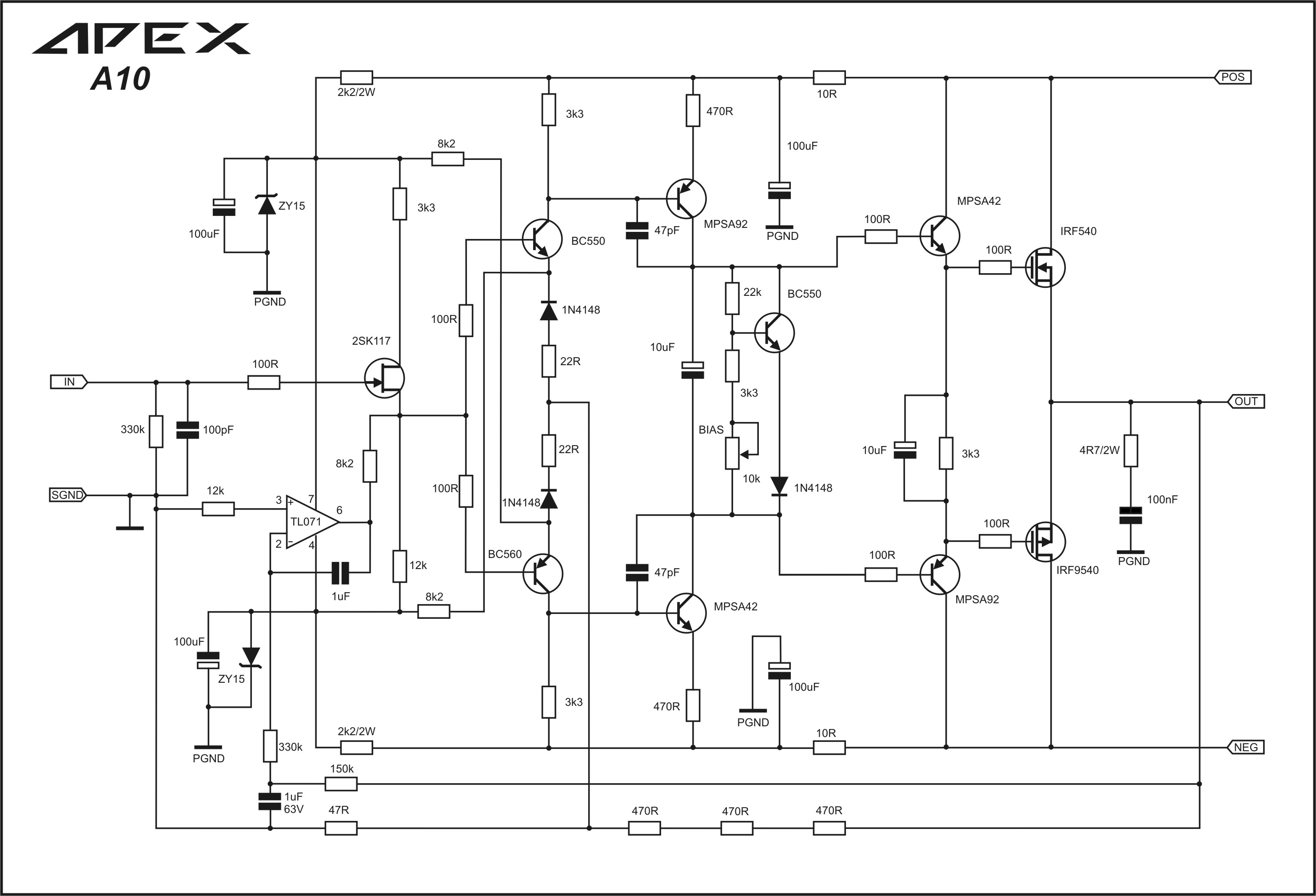
A10:
487833d1434017237-100w-ultimate-fidelity-amplifier-apex-a10.jpg


CA10 - added 8/11/2016 (untested as of this date):
564361d1470875954-100w-ultimate-fidelity-amplifier-apex-ca10.jpg


http://www.diyaudio.com/forums/soli...imate-fidelity-amplifier-834.html#post4799153

N10 - 150w MOSFET amplifier with IRFP250 x2 - added 7/8/2016:
http://www.diyaudio.com/forums/solid-state/163159-150w-mosfet-amplifier-irfp250x2.html

162499d1268565289-150w-mosfet-amplifier-irfp250x2-apex-nmos-amp.jpg


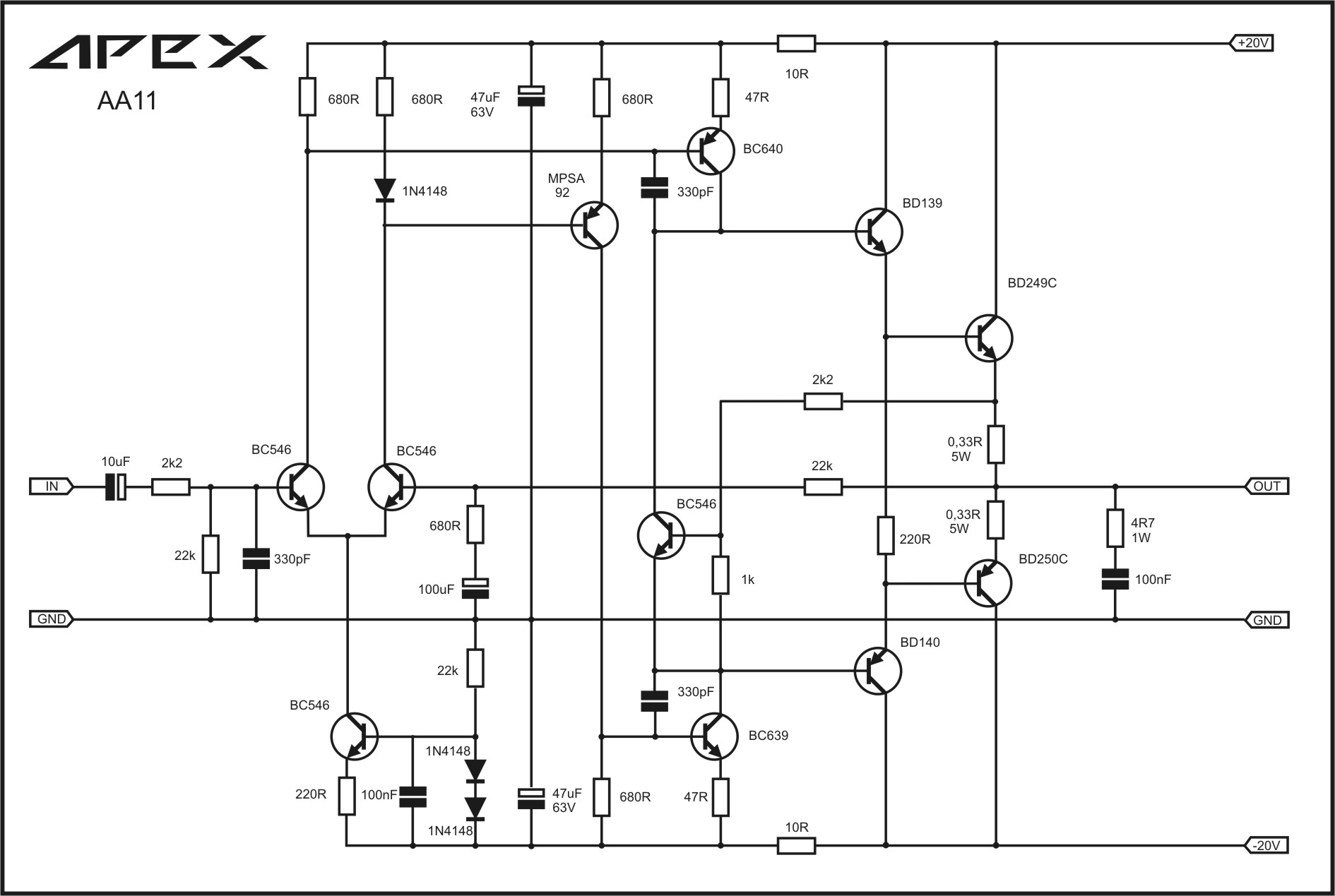
AX11 (50w):
342757d1366040499-100w-ultimate-fidelity-amplifier-apex-ax11sch.jpg


AX11TEF (50w):
536257d1457475704-100w-ultimate-fidelity-amplifier-apex-ax11tef.jpg


AA11 (class A):
537337d1457974999-100w-ultimate-fidelity-amplifier-apex-aa11sch.jpg


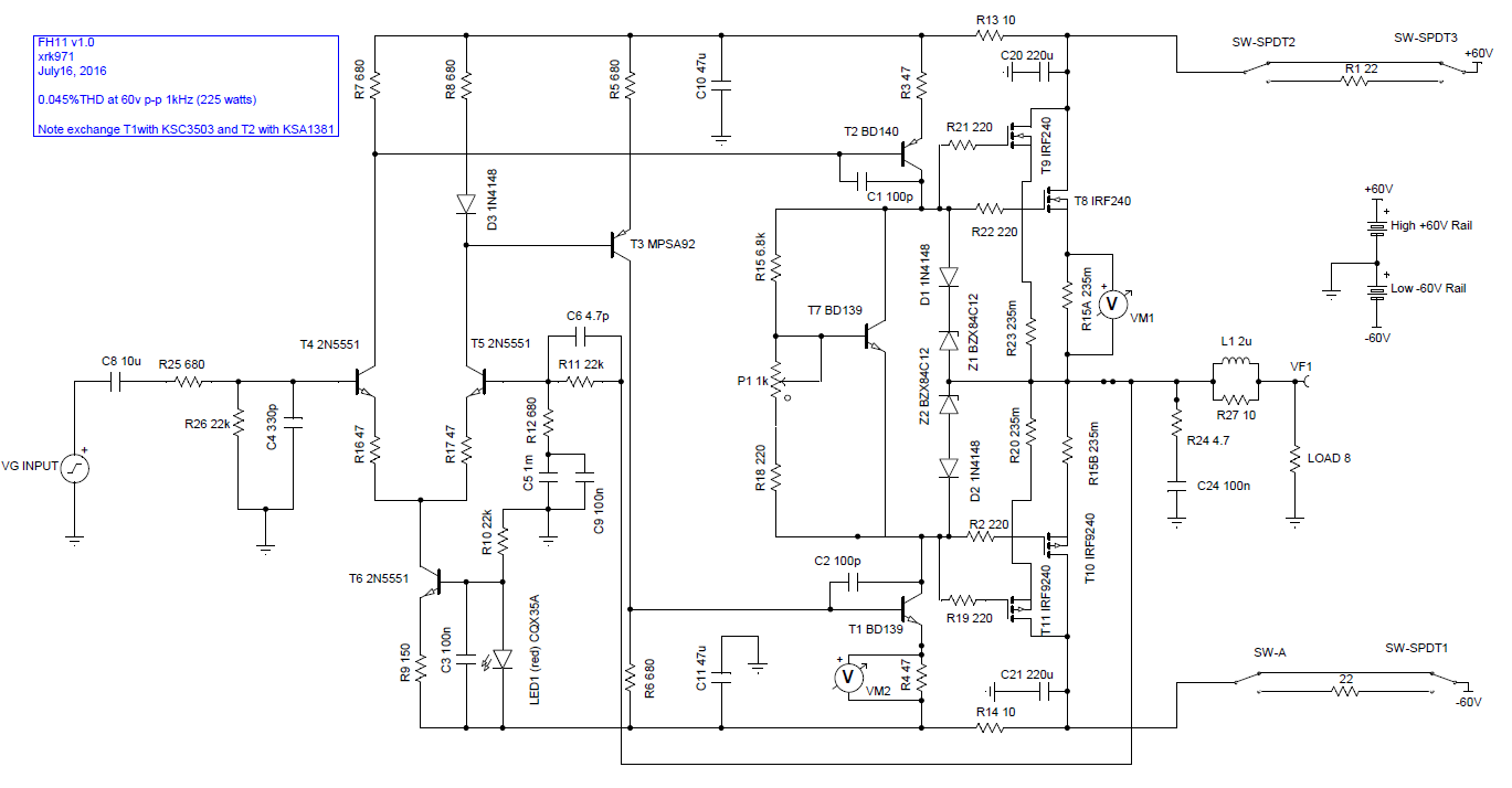
FH11 (250w 8R with 60v rails hexFET amp) Mod by xrk971 based on FH9HV design - added July 19, 2016:
560704d1468819884-100w-ultimate-fidelity-amplifier-fh11-schematic-v1.0.png


http://www.diyaudio.com/forums/soli...imate-fidelity-amplifier-805.html#post4777079

Simulation:
http://www.diyaudio.com/forums/soli...imate-fidelity-amplifier-801.html#post4775467

Verified build tested by Andrewlebon (note typo on MJE350 layout in middle of board - legs are ECB not EBC):
http://www.diyaudio.com/forums/soli...imate-fidelity-amplifier-809.html#post4778364

Built and tested by Still4given:
http://www.diyaudio.com/forums/soli...imate-fidelity-amplifier-810.html#post4778451


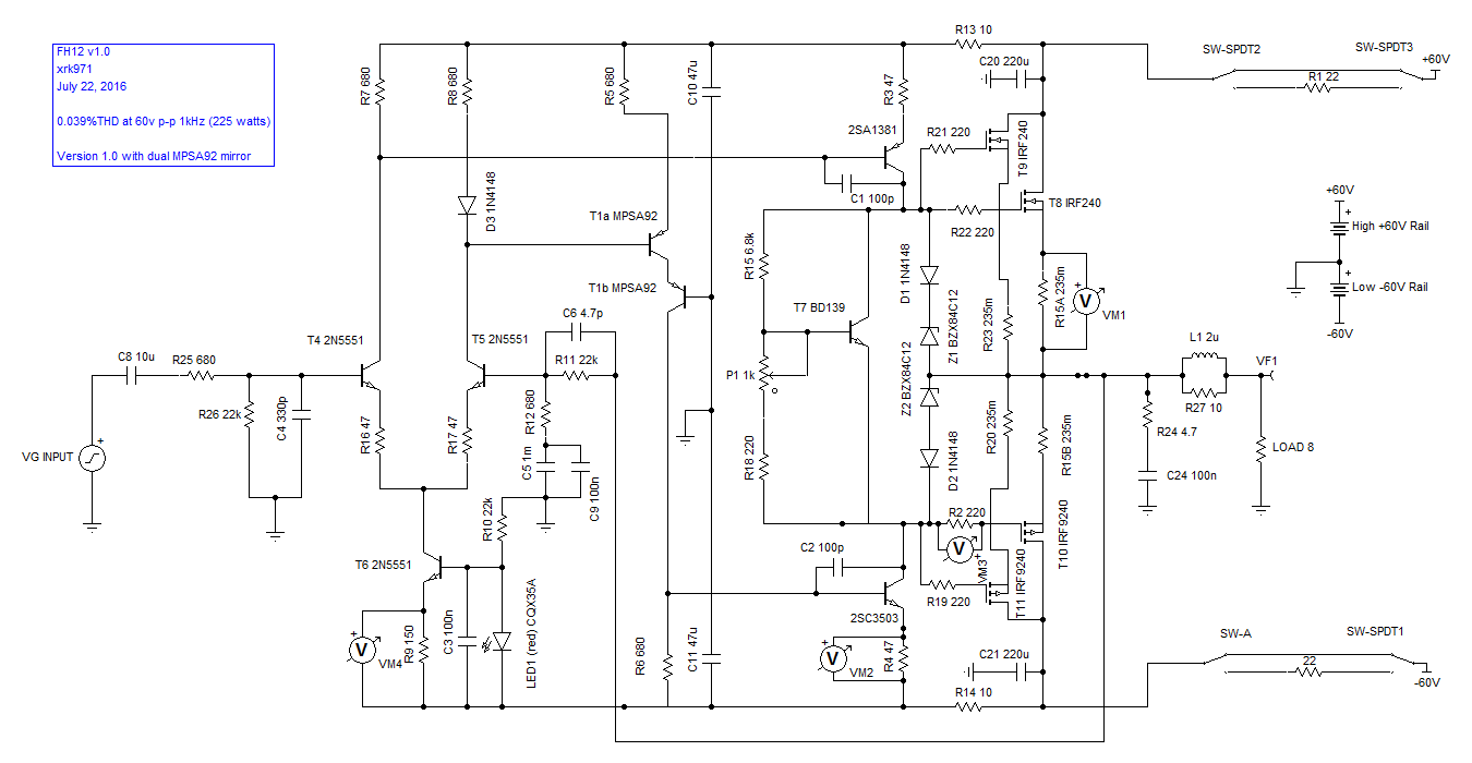
FH12 (mod to reduce dissipation on current mirror) - 0.039% THD at 1kHz 60v p-p output in simulation, not yet tested - added July 22, 2016:

http://www.diyaudio.com/forums/soli...imate-fidelity-amplifier-816.html#post4780667

561303d1469190988-100w-ultimate-fidelity-amplifier-fh12-schematic-tina-v1.0.png


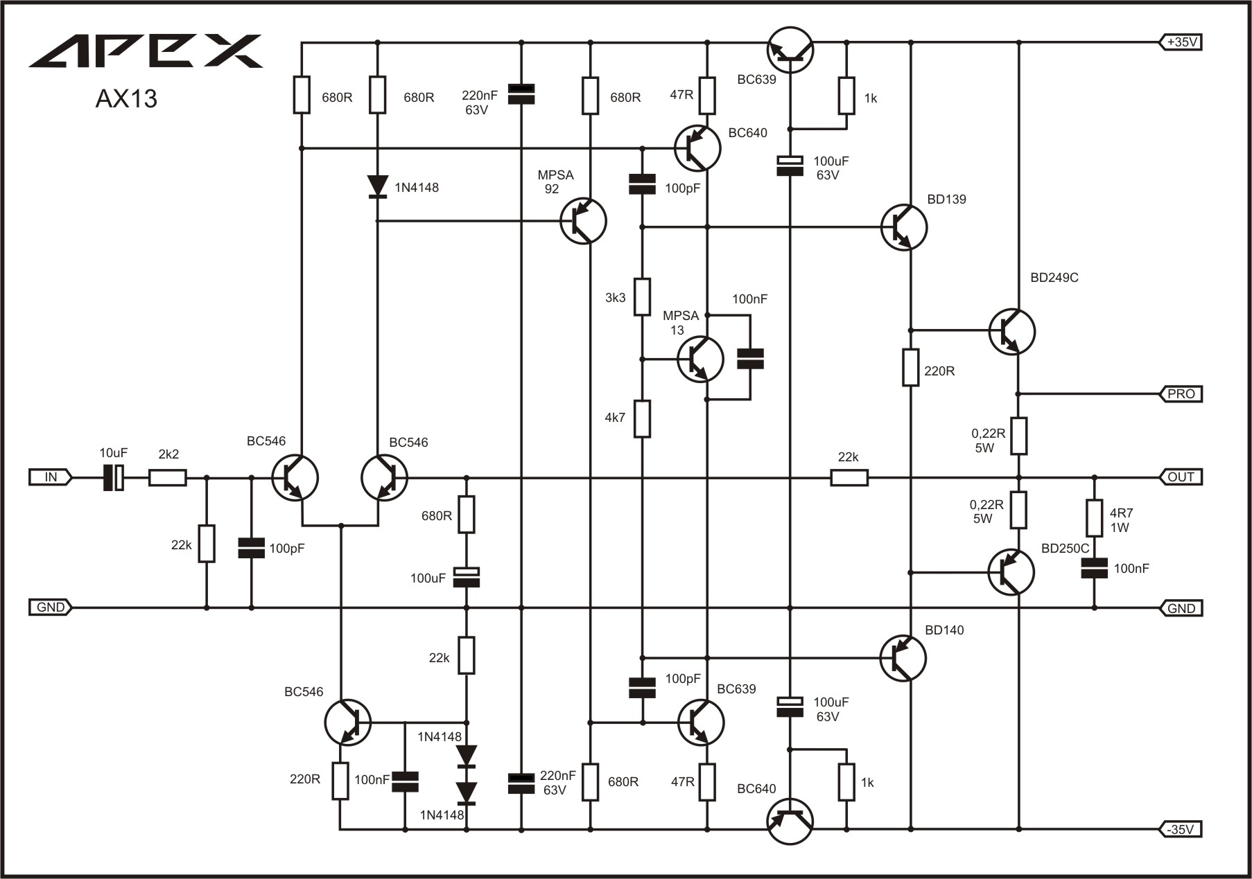
AX13 (50w?):
347374d1367973319-100w-ultimate-fidelity-amplifier-apex-ax13sch.jpg


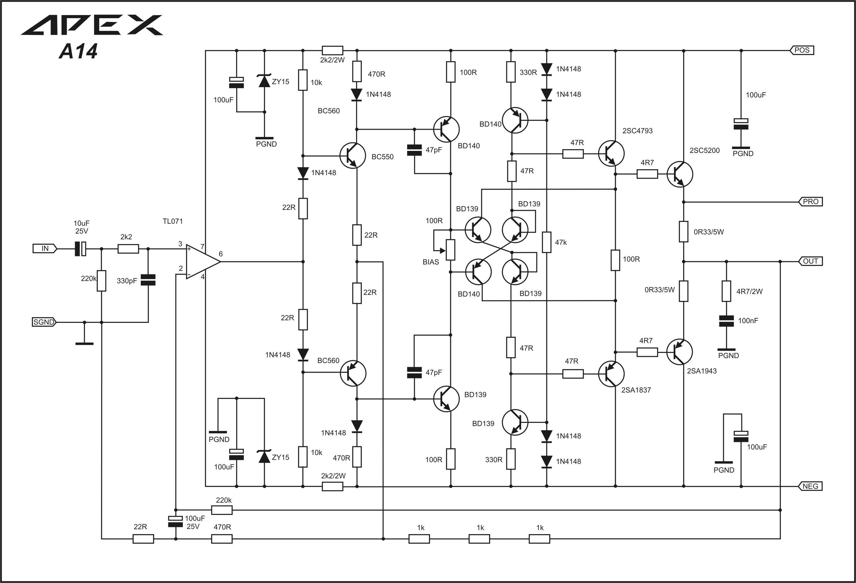
A14 (CFA 35v rails) - added 6/22/2016
456005d1419793552-100w-ultimate-fidelity-amplifier-apex-a14.jpg


Successful build and tested by Olafk:
100W Ultimate Fidelity Amplifier

PCB Files:
http://www.diyaudio.com/forums/soli...imate-fidelity-amplifier-400.html#post4168322

Sprint Files:
http://www.diyaudio.com/forums/soli...imate-fidelity-amplifier-400.html#post4168814

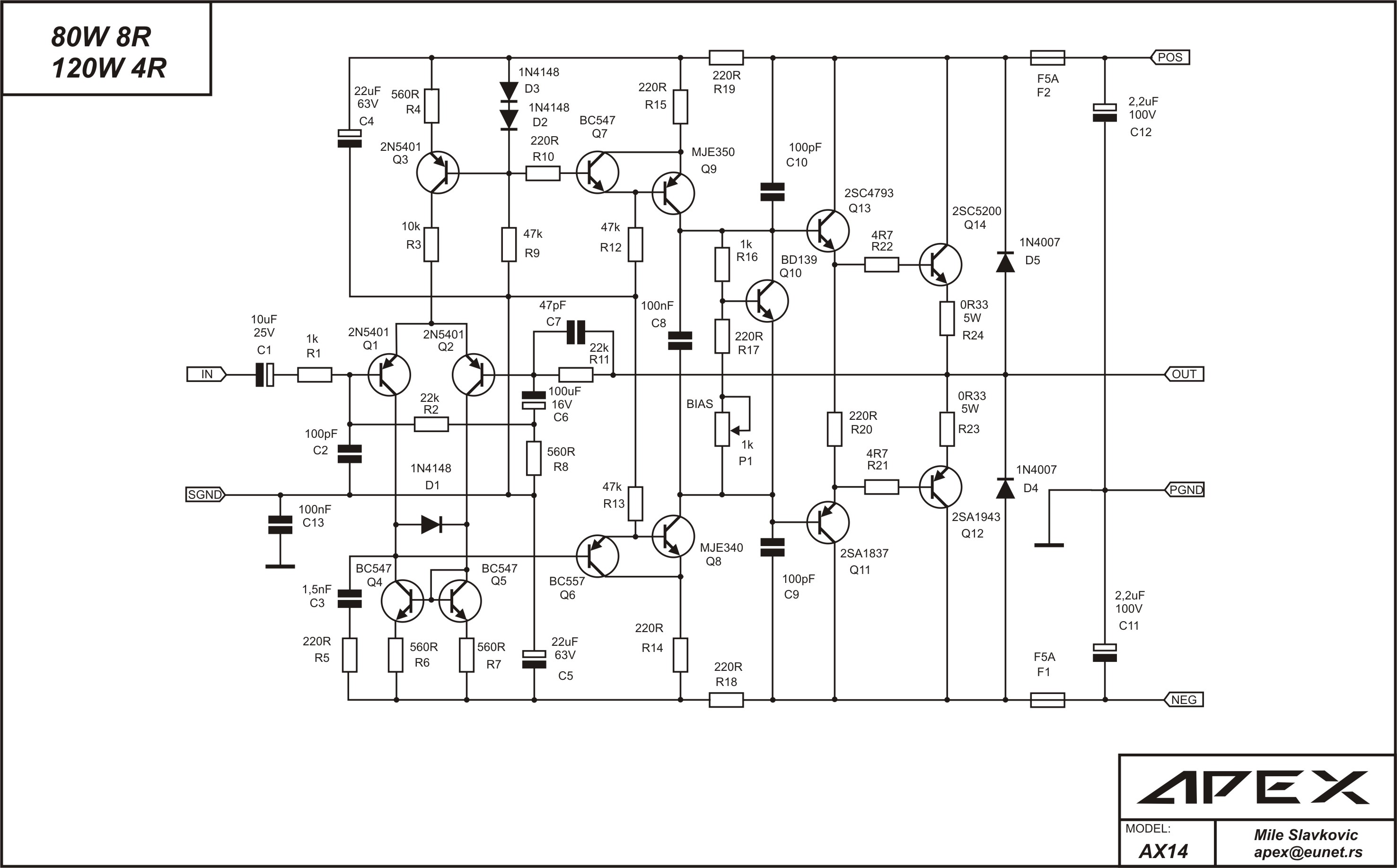
AX14 (80w):
167581d1271628000-100w-ultimate-fidelity-amplifier-apex-kelvin-v2.jpg


AX14 with dual outputs - mod by Vargas Mongo:

http://www.diyaudio.com/forums/soli...imate-fidelity-amplifier-772.html#post4753185


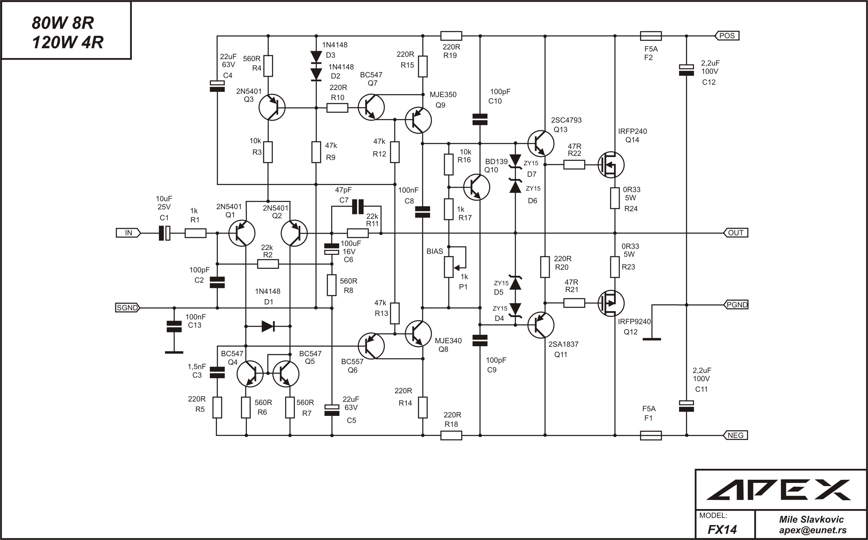
FX14 vertical MOSFET (80w):
178830d1278159595-100w-ultimate-fidelity-amplifier-apex-fx14.jpg


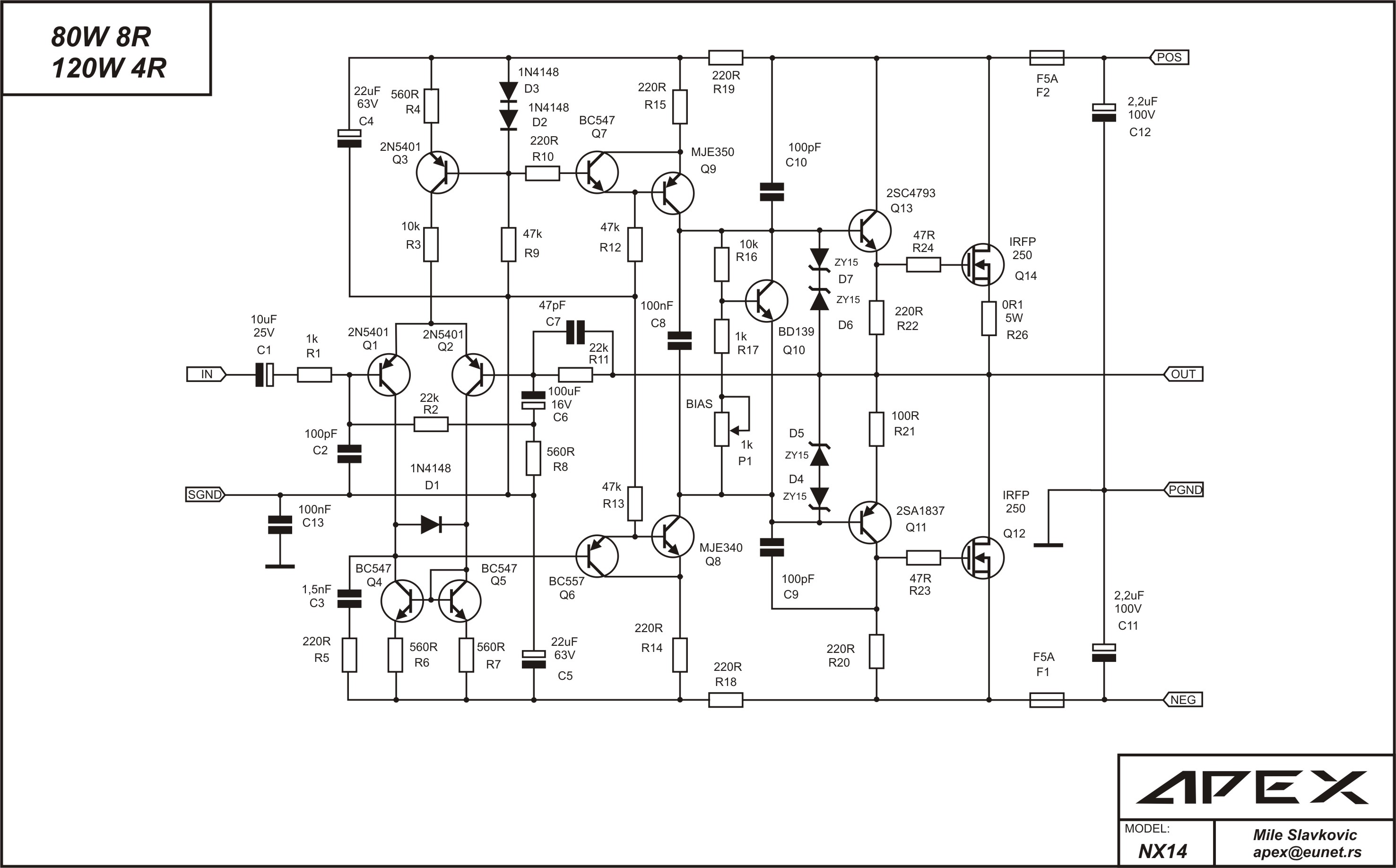
NX14 NMOS amp (80w):
179301d1278422412-100w-ultimate-fidelity-amplifier-apex-nx14.2.jpg


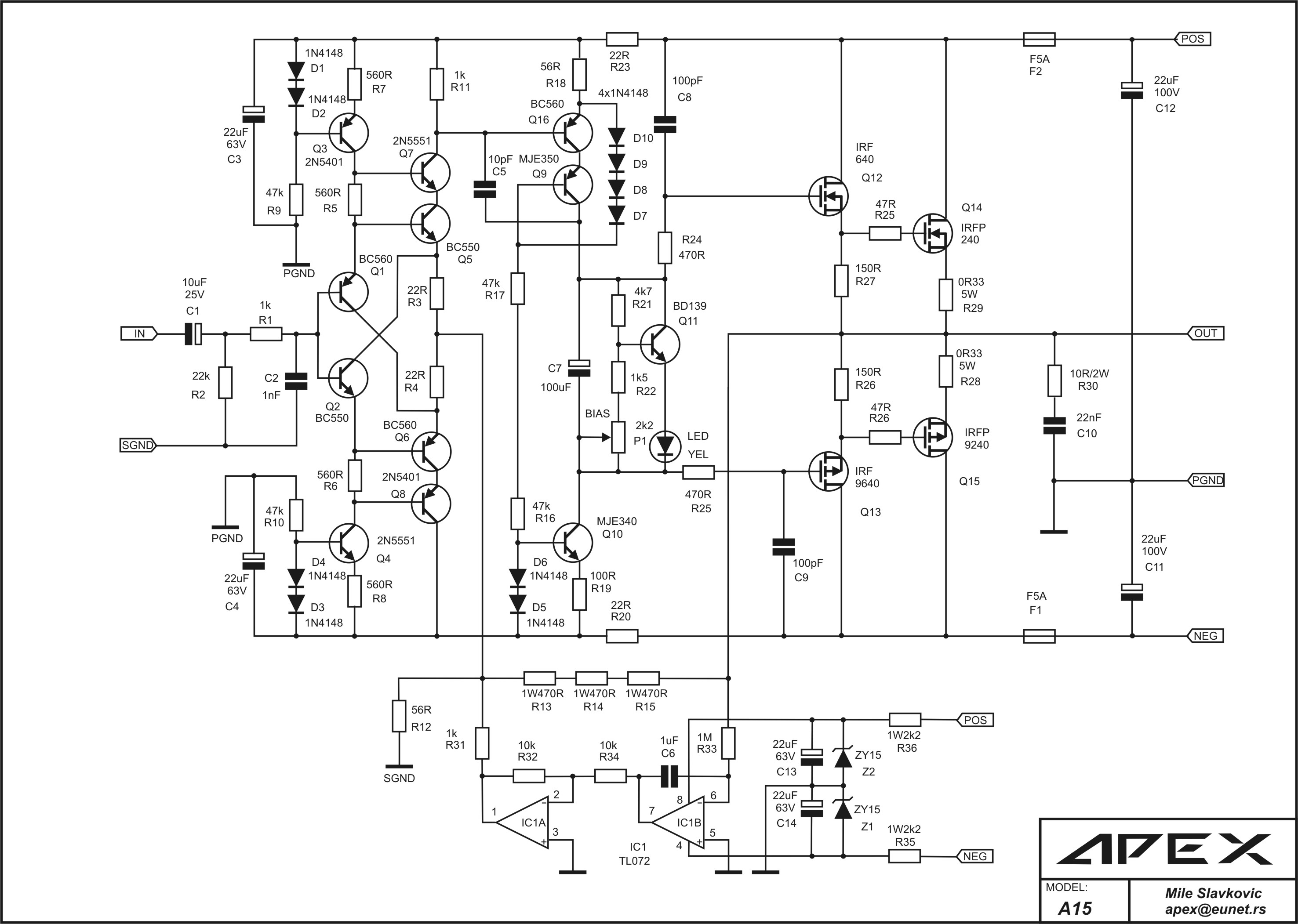
A15:
552740d1464834882-directory-apex-audio-amplifiers-apex-a15.jpg


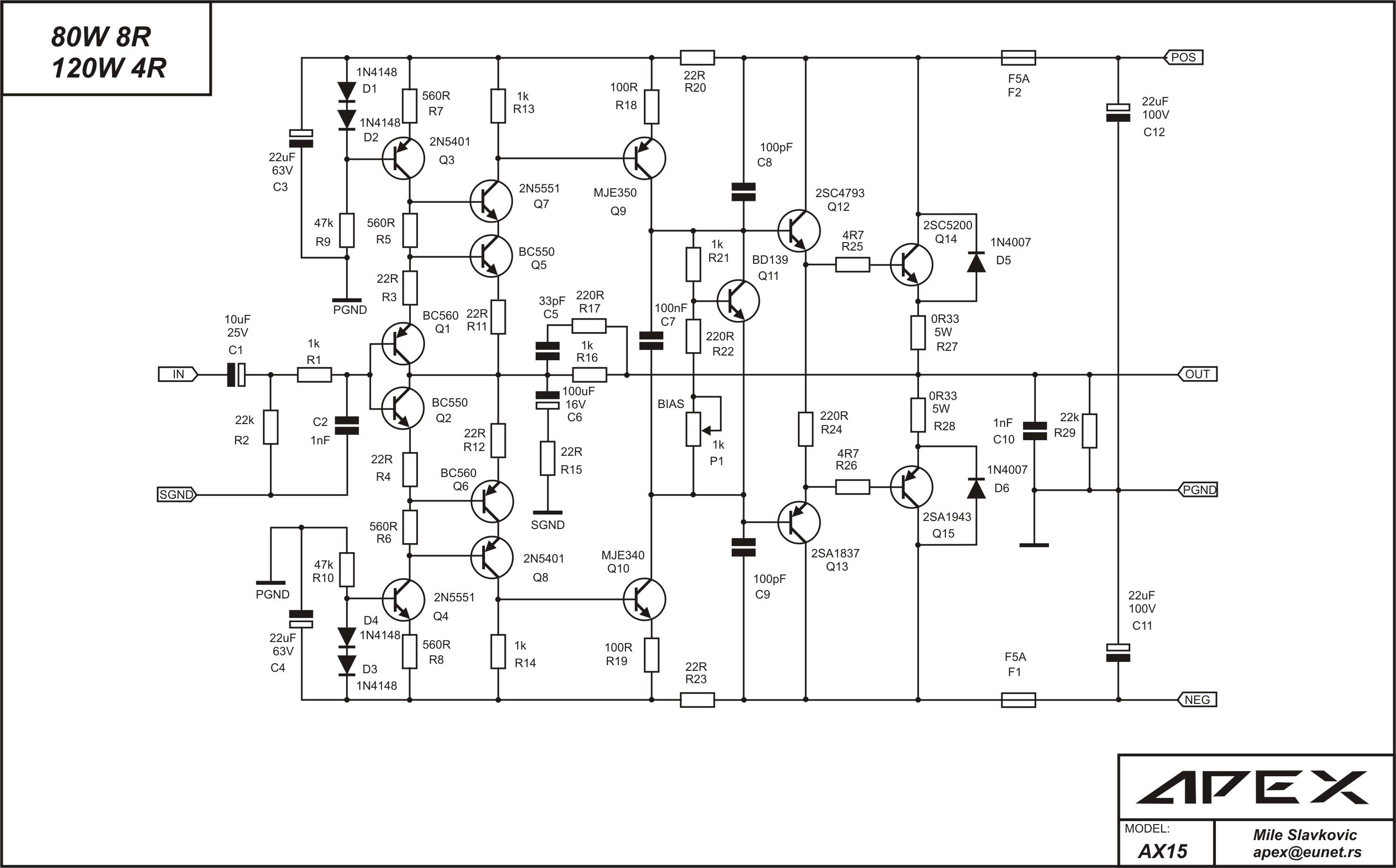
AX15 (80w full symmetric amp):
246036d1319407815-100w-ultimate-fidelity-amplifier-apex-ax15.jpg


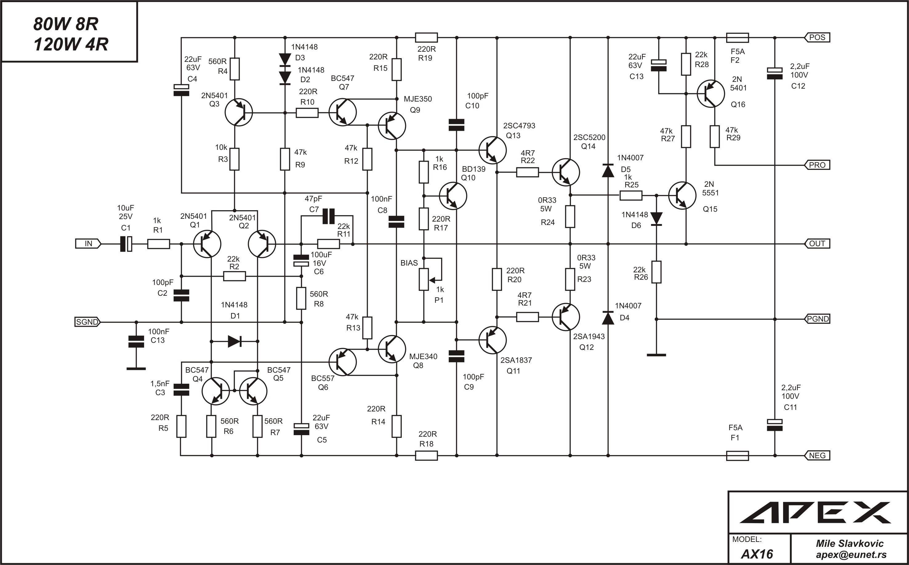
AX16 (80w):
179202d1278348376-100w-ultimate-fidelity-amplifier-apex-ax16.jpg


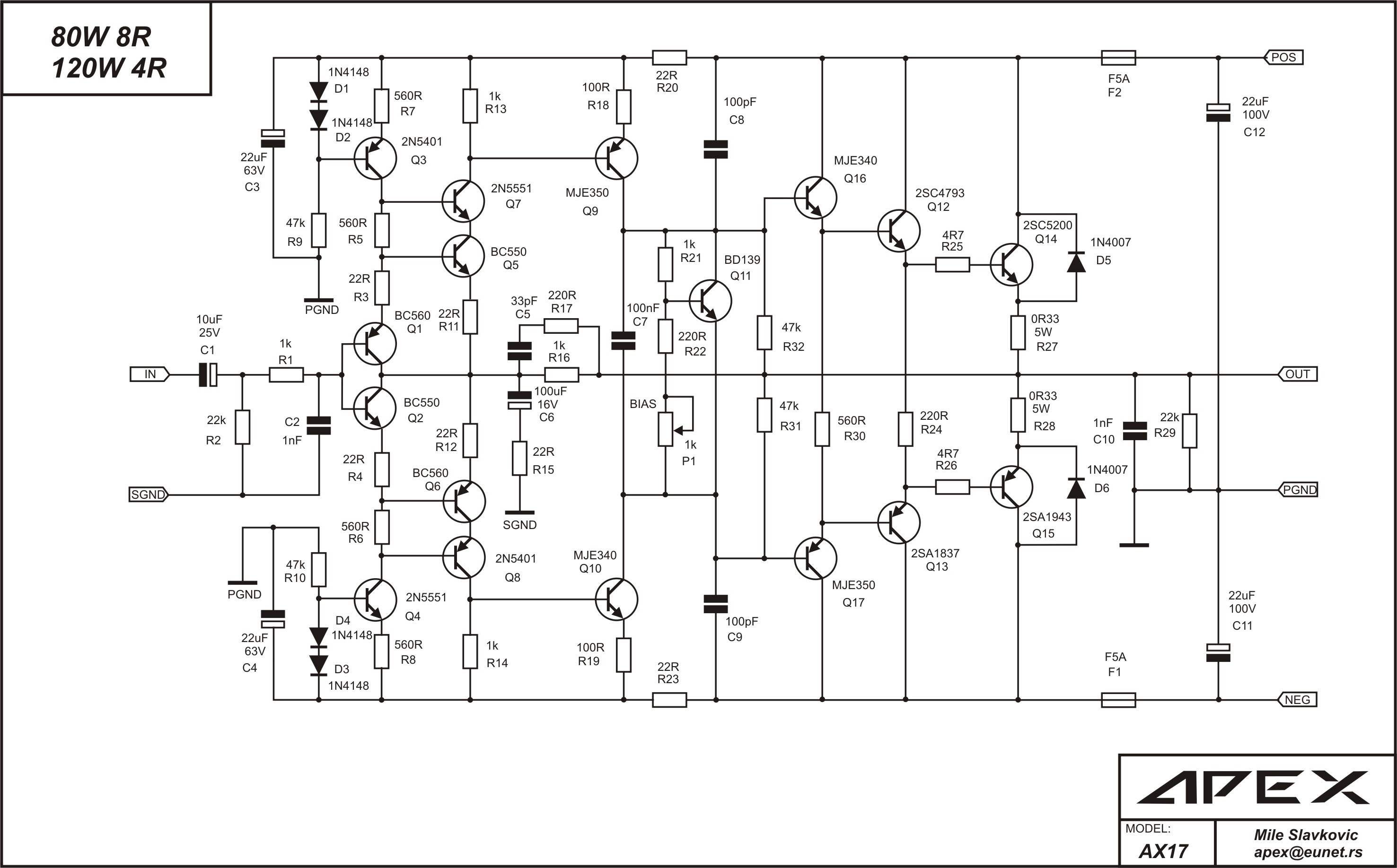
AX17 (80w):
246444d1319579956-100w-ultimate-fidelity-amplifier-apex-ax17.jpg


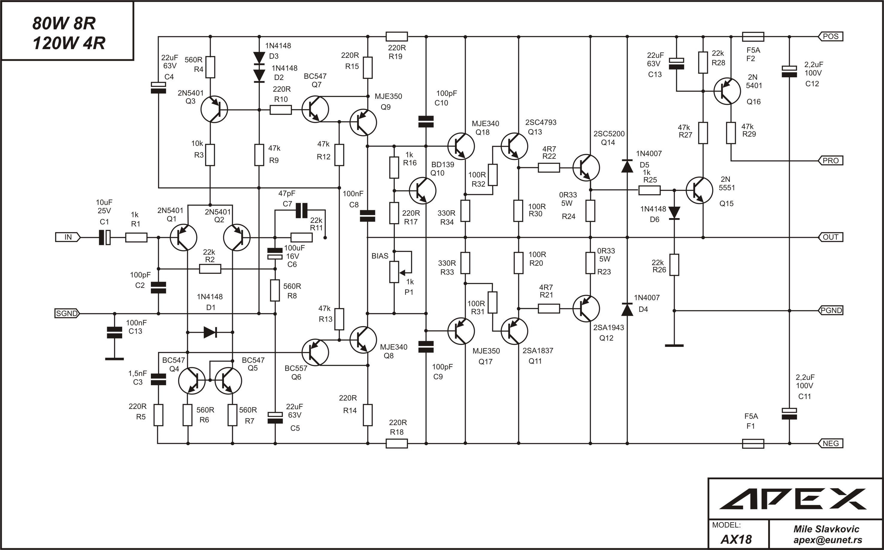
AX18 (80w):
246153d1319466566-100w-ultimate-fidelity-amplifier-apex-ax18.jpg


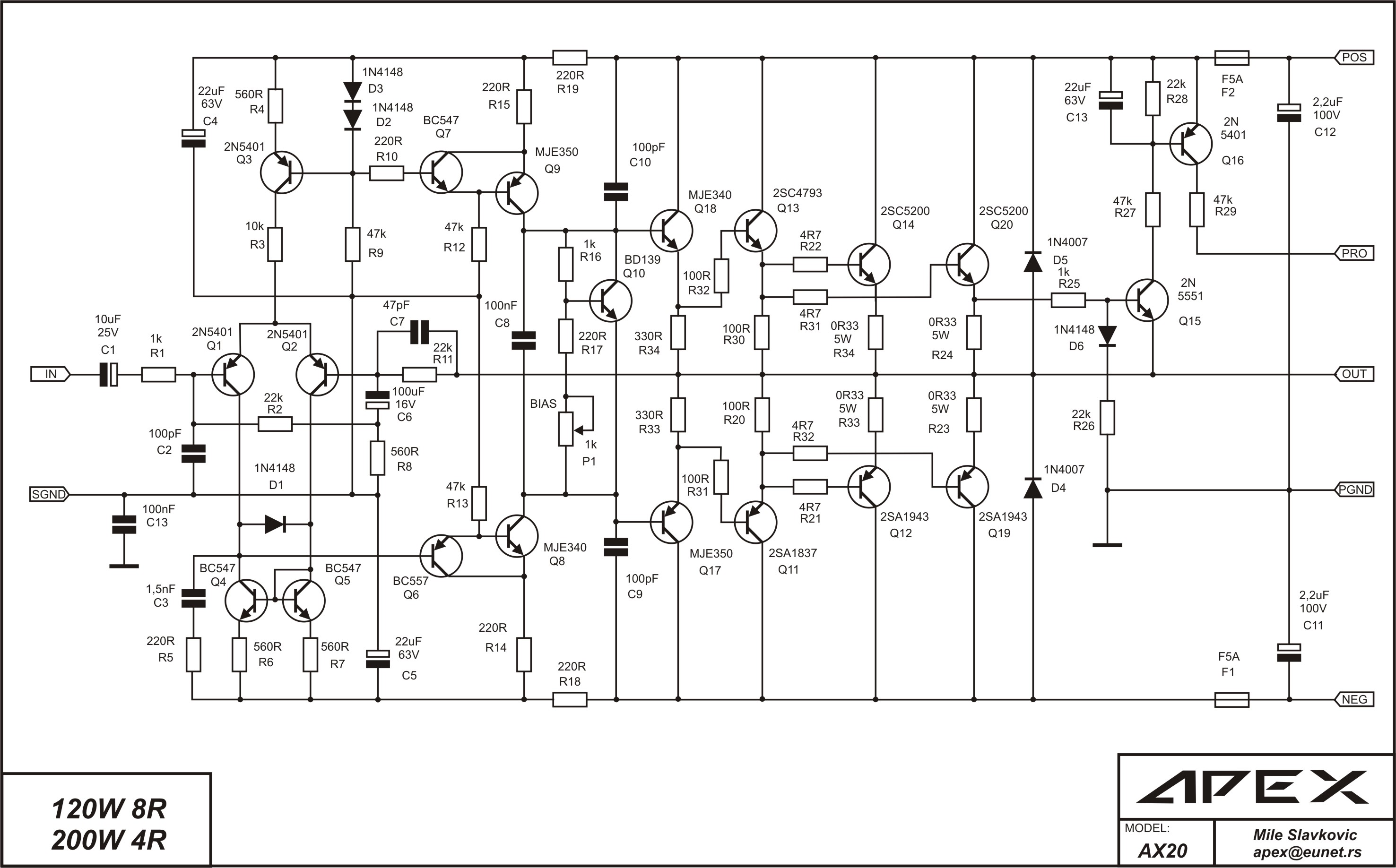
AX20 (120w):
246443d1319578391-100w-ultimate-fidelity-amplifier-apex-ax20.jpg


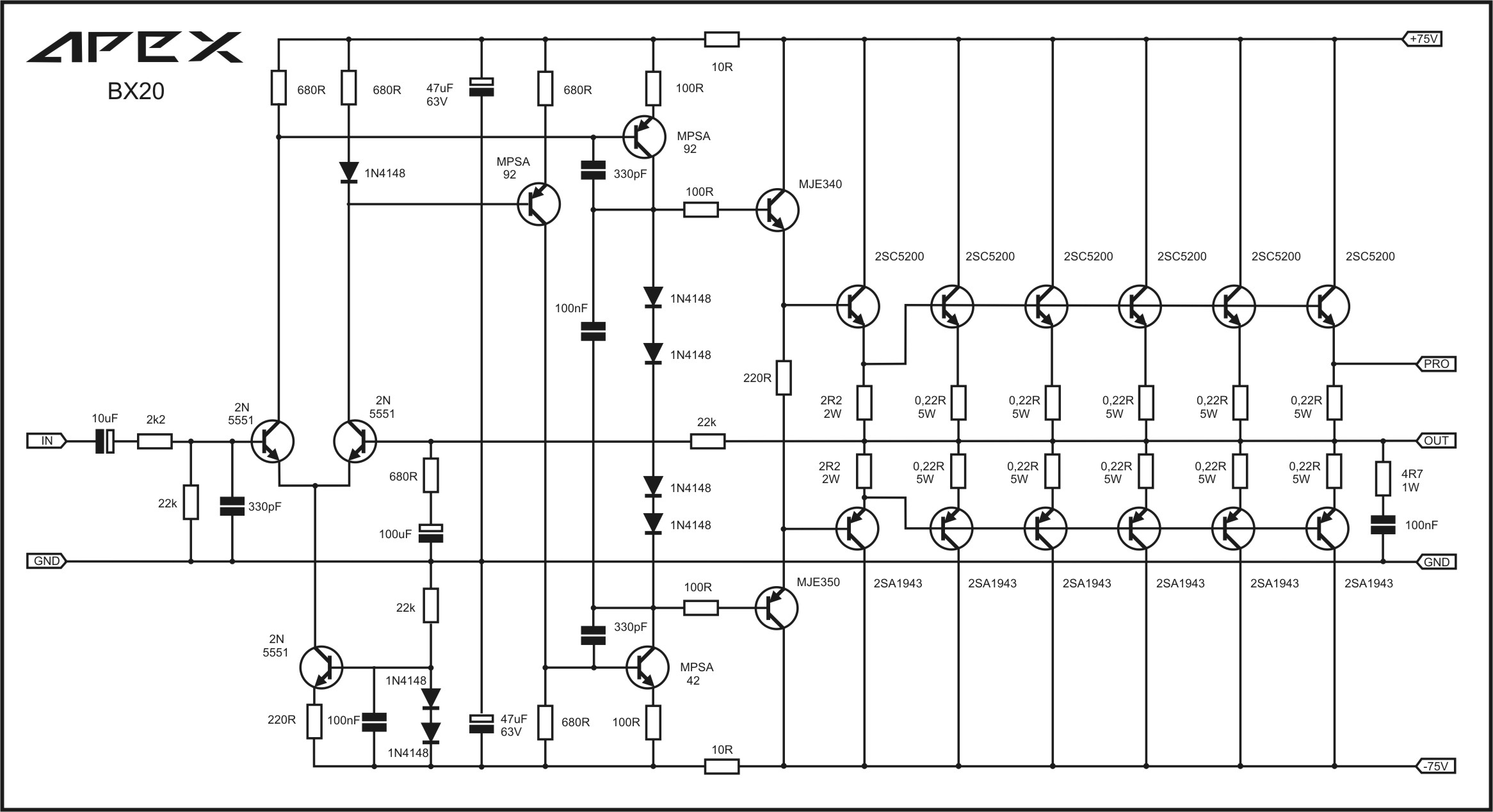
BX20 (w?):
536674d1457638070-100w-ultimate-fidelity-amplifier-apex-bx20.jpg


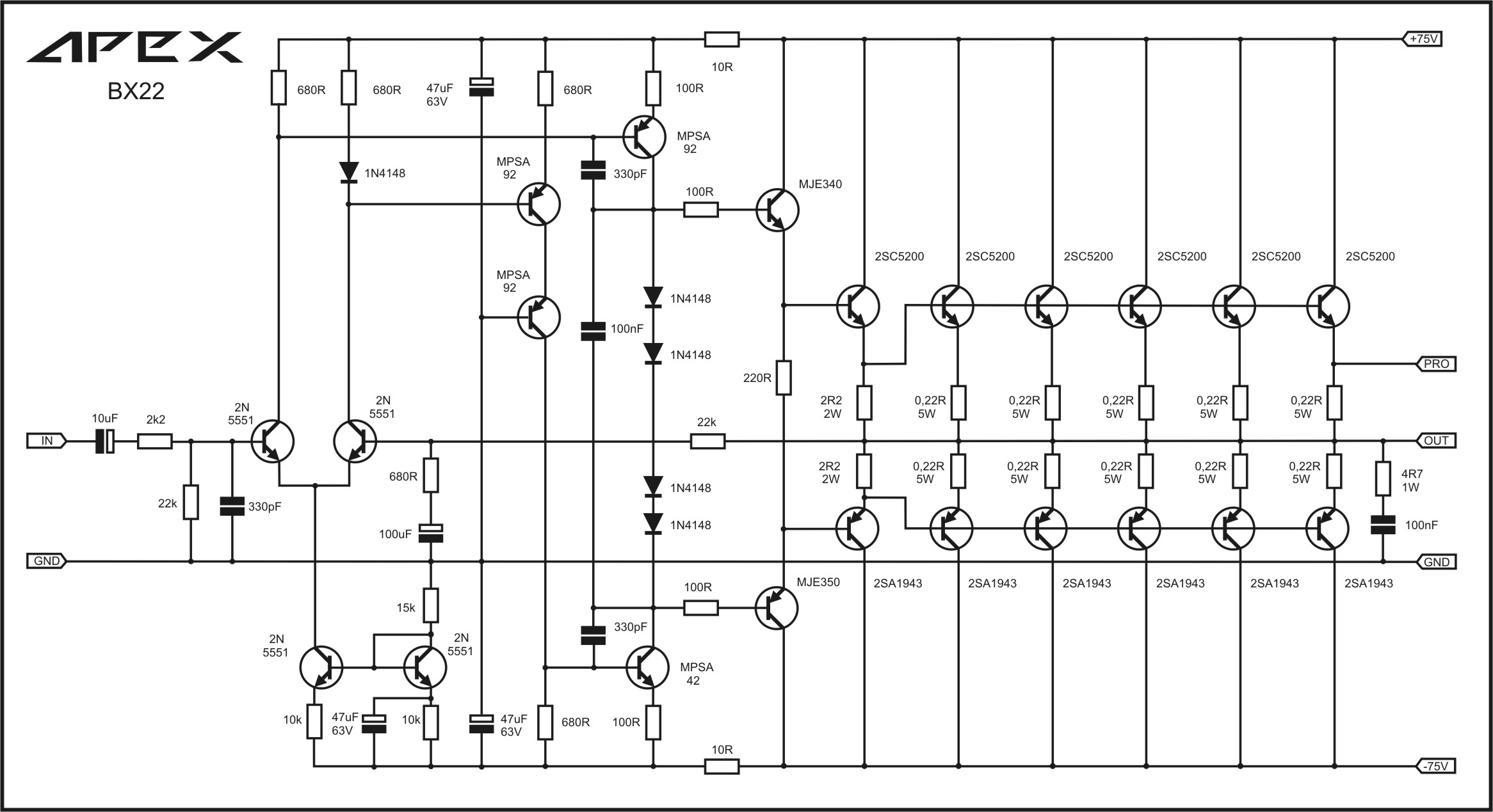
BX22 - added 6/24/2016:
561589d1469373906-100w-ultimate-fidelity-amplifier-apex-bx22.jpg


100W Ultimate Fidelity Amplifier
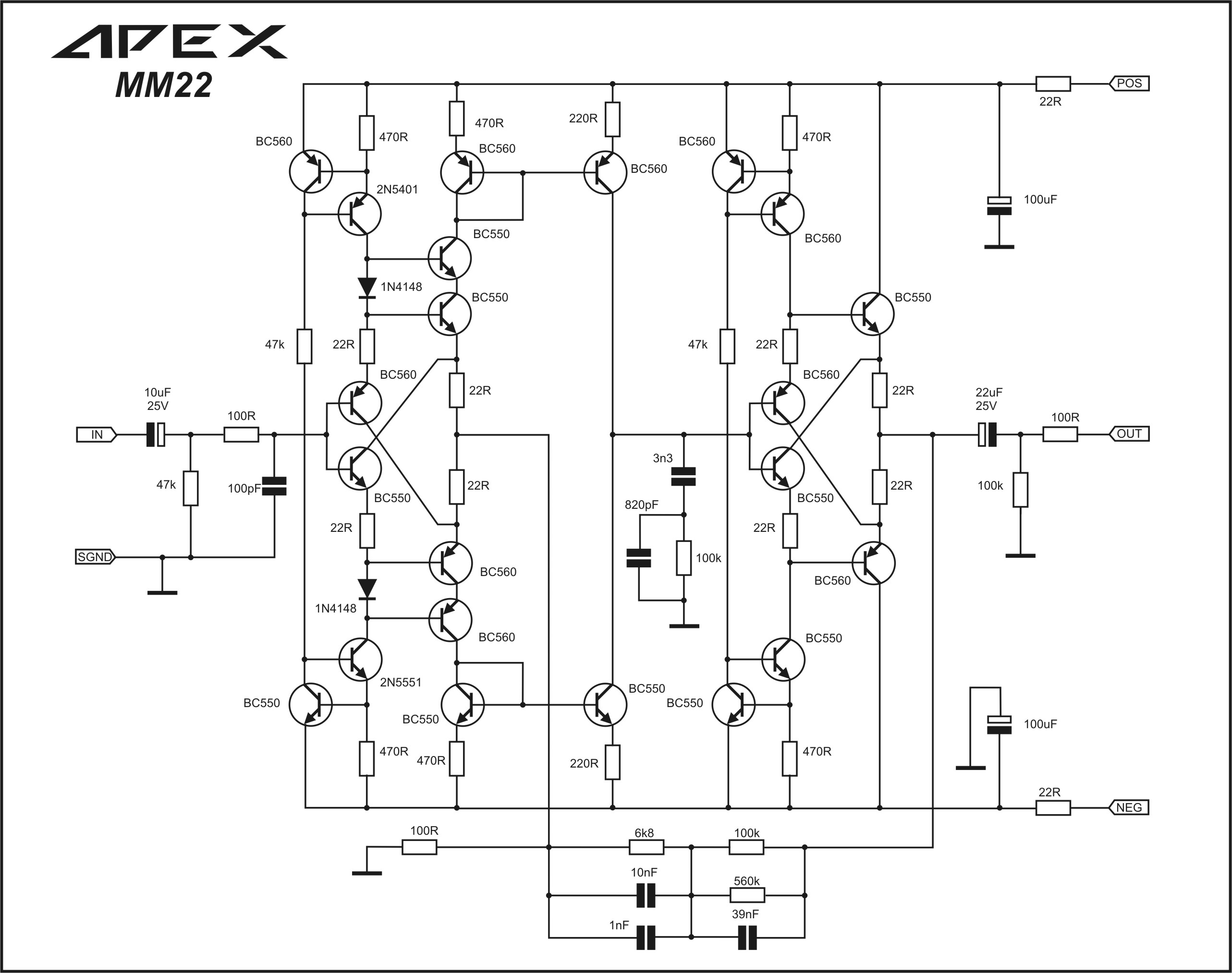
MM22 (phono preamp) - added 6/22/2016:
457735d1420560709-100w-ultimate-fidelity-amplifier-apex-mm22.jpg


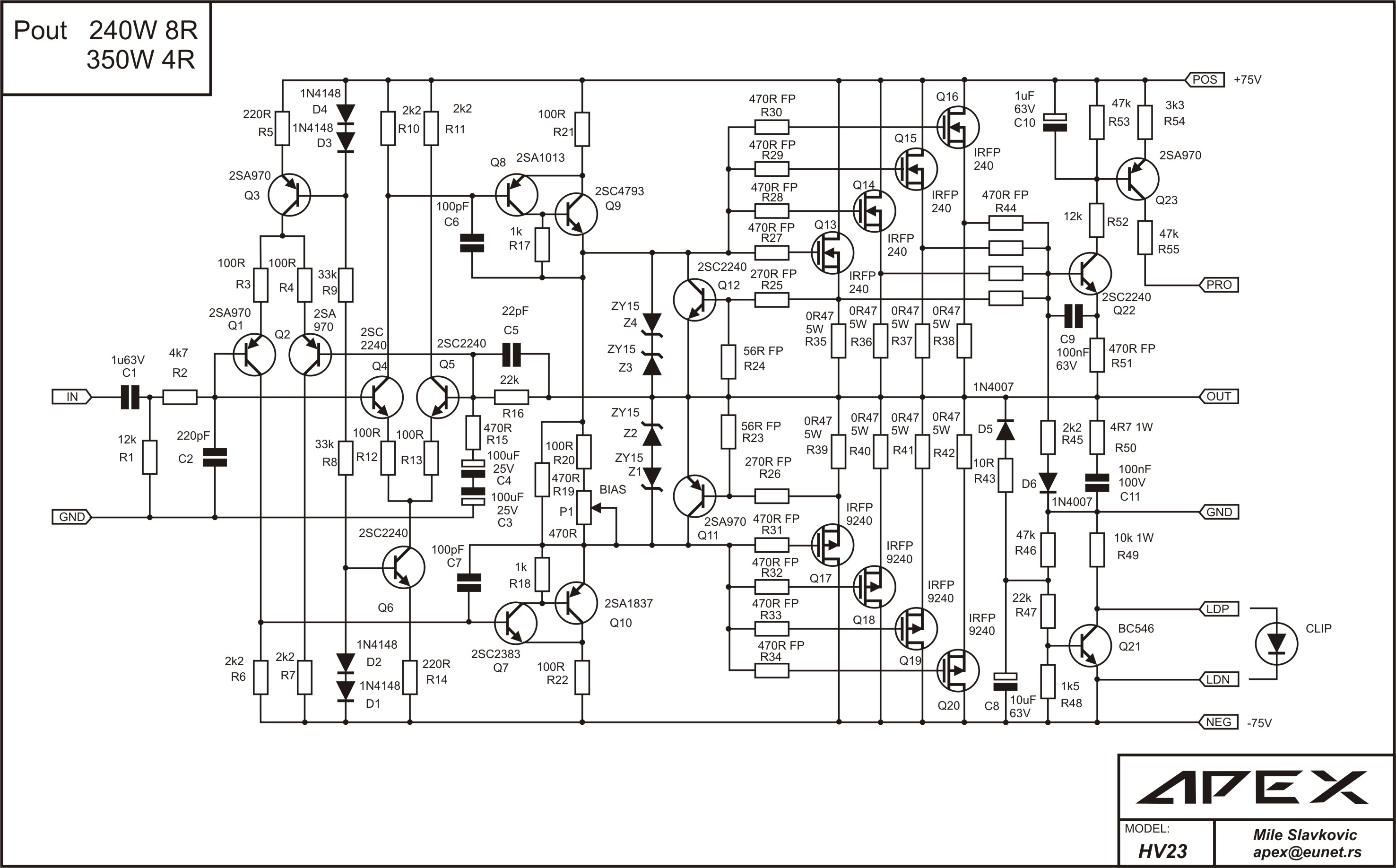
HV23 (750w into 8R) quadruple vertical MOSFET amp - added 6/2/2016:

http://www.diyaudio.com/forums/soli...mplifier-irfp240-irfp9240-47.html#post2802550

252508d1322772159-mosfet-amplifier-irfp240-irfp9240-apex-mosfet-hv23-sch.jpg


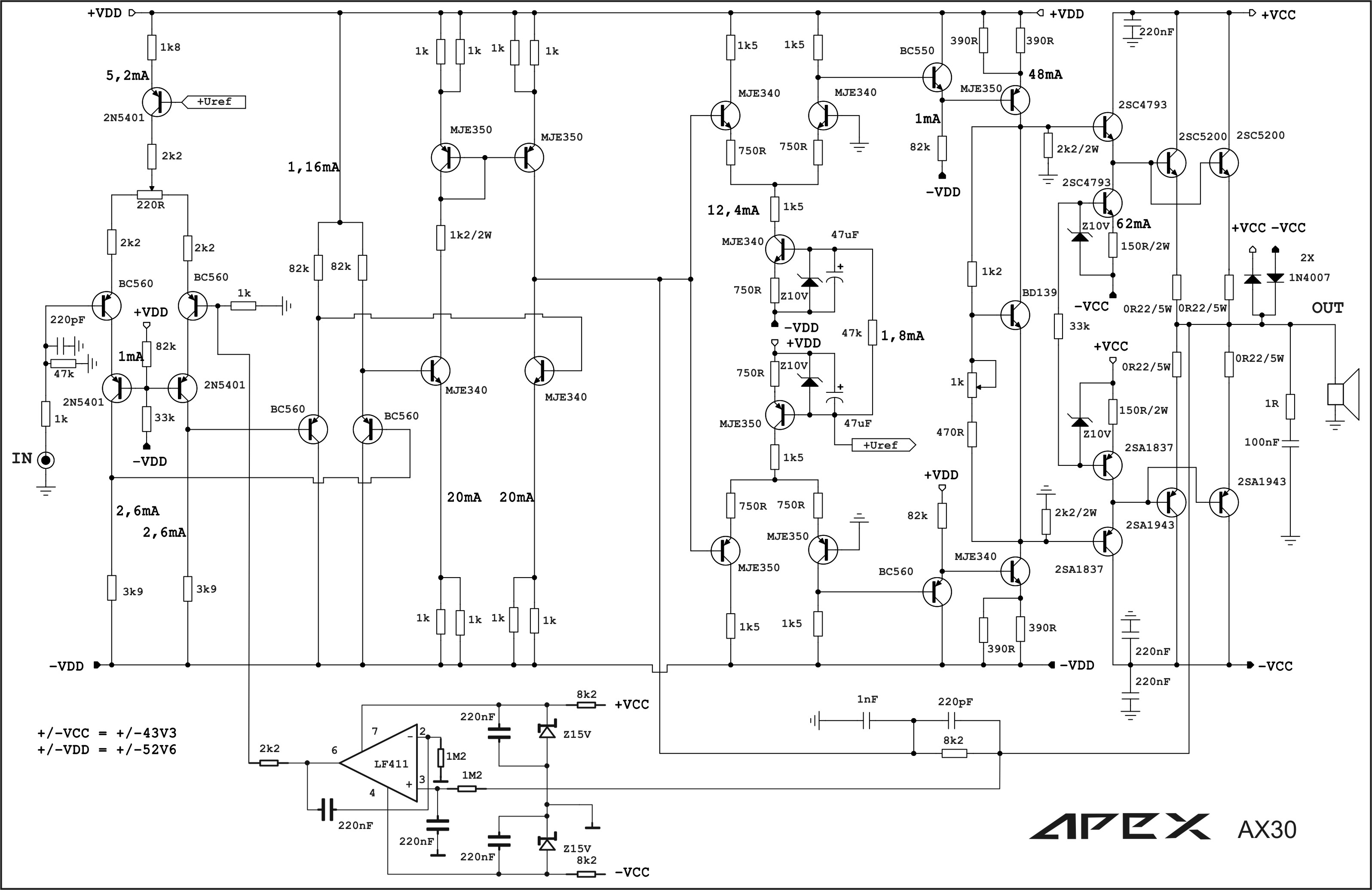
AX30 (w?):
519308d1450126875-100w-ultimate-fidelity-amplifier-apex-ax30.jpg


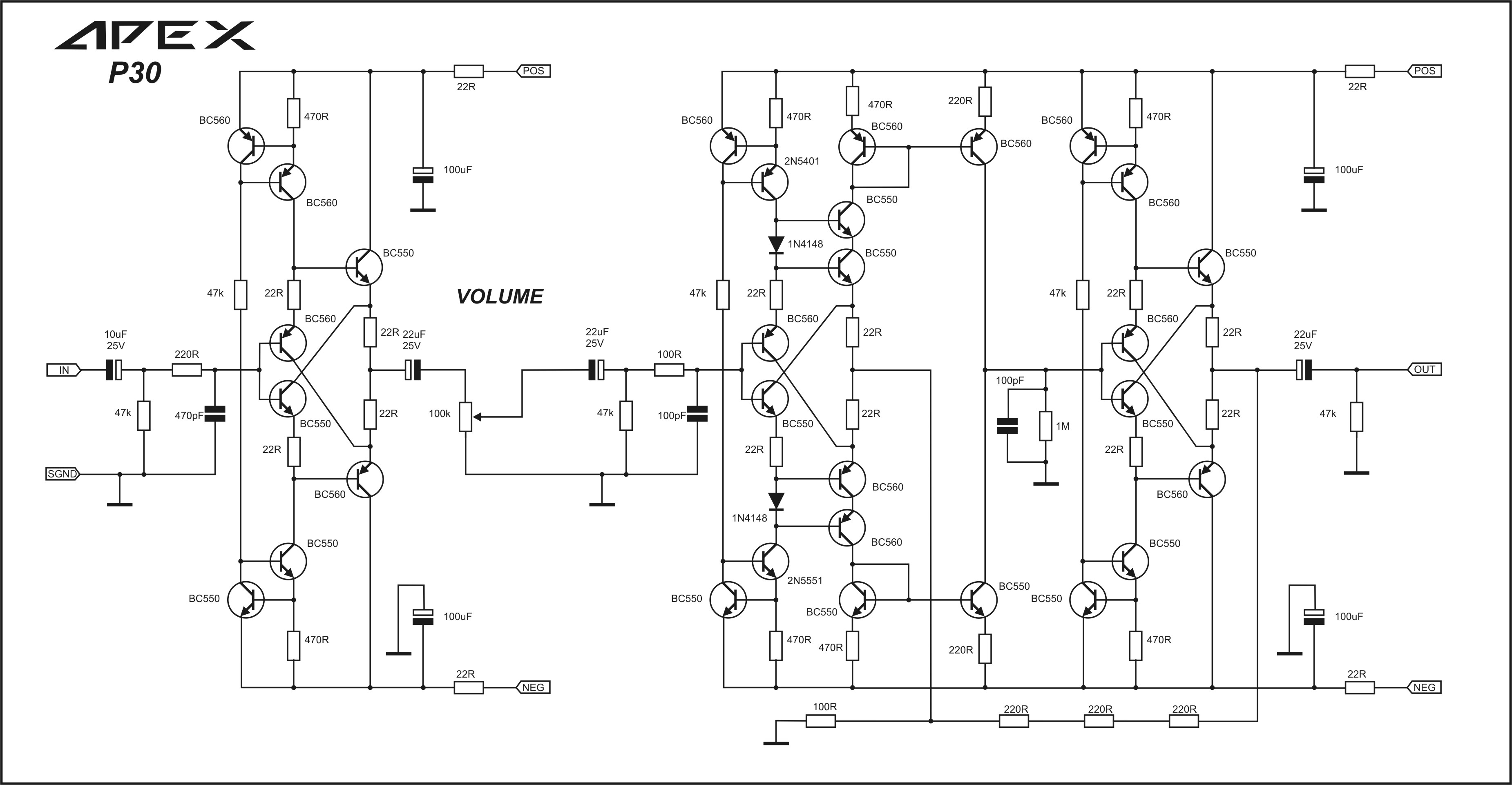
P30 preamp (24v rails, 300mV in 2V out) - added 6/22/2016:
http://www.diyaudio.com/forums/soli...imate-fidelity-amplifier-405.html#post4175807

457723d1420554364-100w-ultimate-fidelity-amplifier-apex-p30.jpg


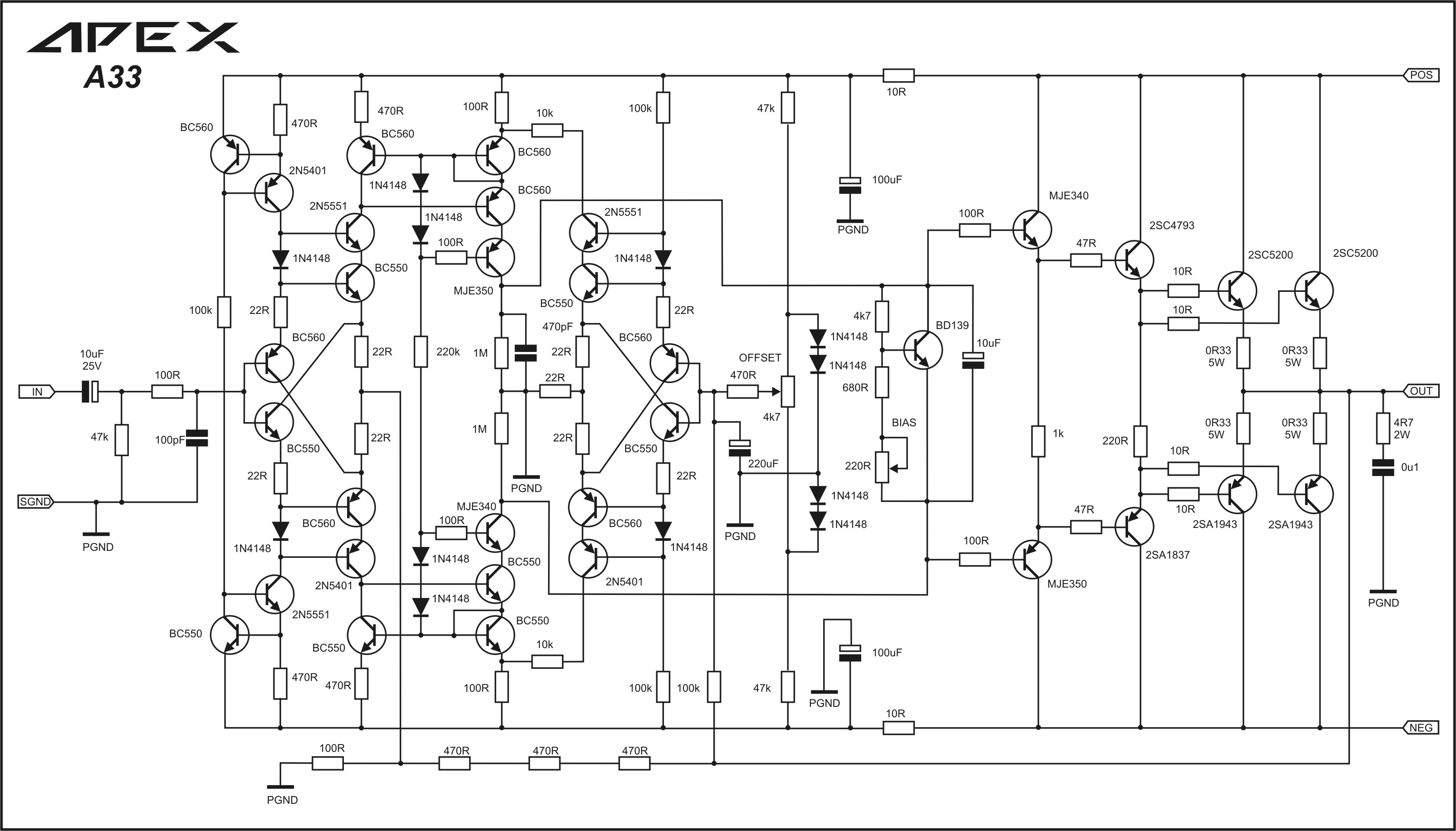
A33 - edit July 26, 2016 - note that resistor at offset trimpot is 470k not 470R per Apex.
451846d1417544972-100w-ultimate-fidelity-amplifier-apex-a33.jpg


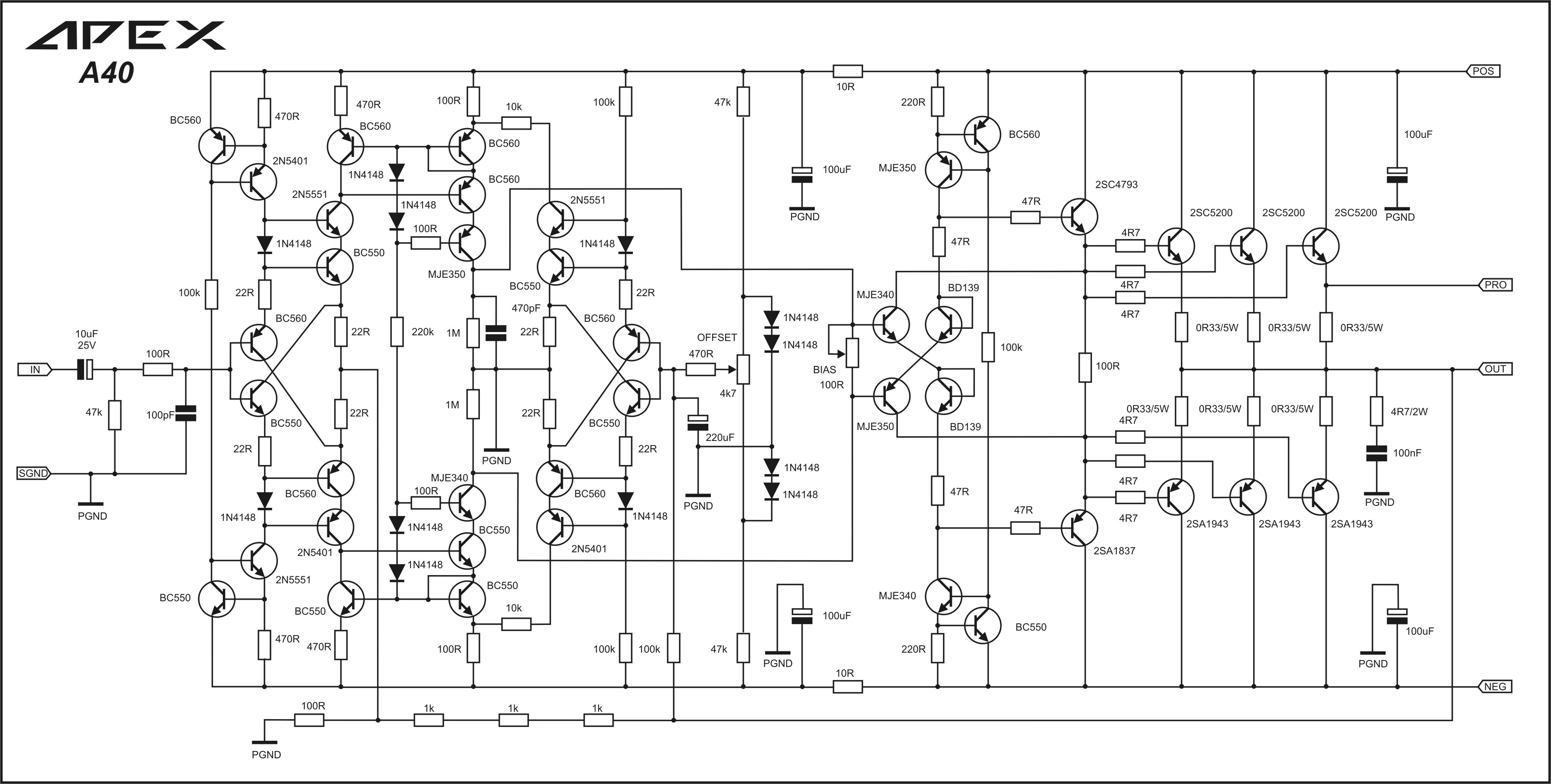
A40 (?w):
461233d1422093709-100w-ultimate-fidelity-amplifier-apex-a40.jpg


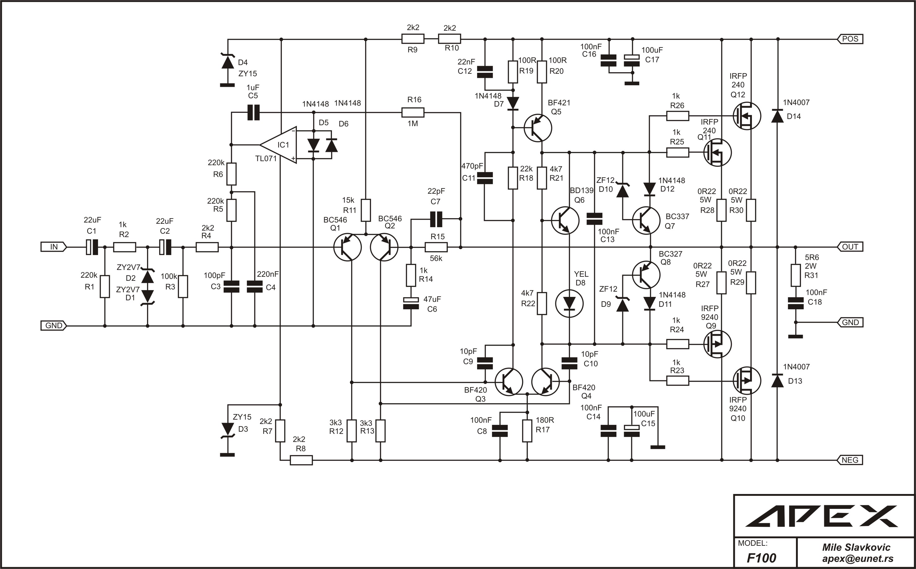
F100 (80w into 8R) dual vertical MOSFET amp with DC servo - Apex says over 400 units installed and working reliably in bars/nightclubs etc, added 6/2/2016:

DC Servo MOSFET Amplifier

163352d1269048660-dc-servo-mosfet-amplifier-harissonsch.jpg


H100 (80w into 8R) high efficiency class H amp - added 6/2/2016:

DC Servo MOSFET Amplifier

178981d1278236637-dc-servo-mosfet-amplifier-apex-h210-sch.jpg


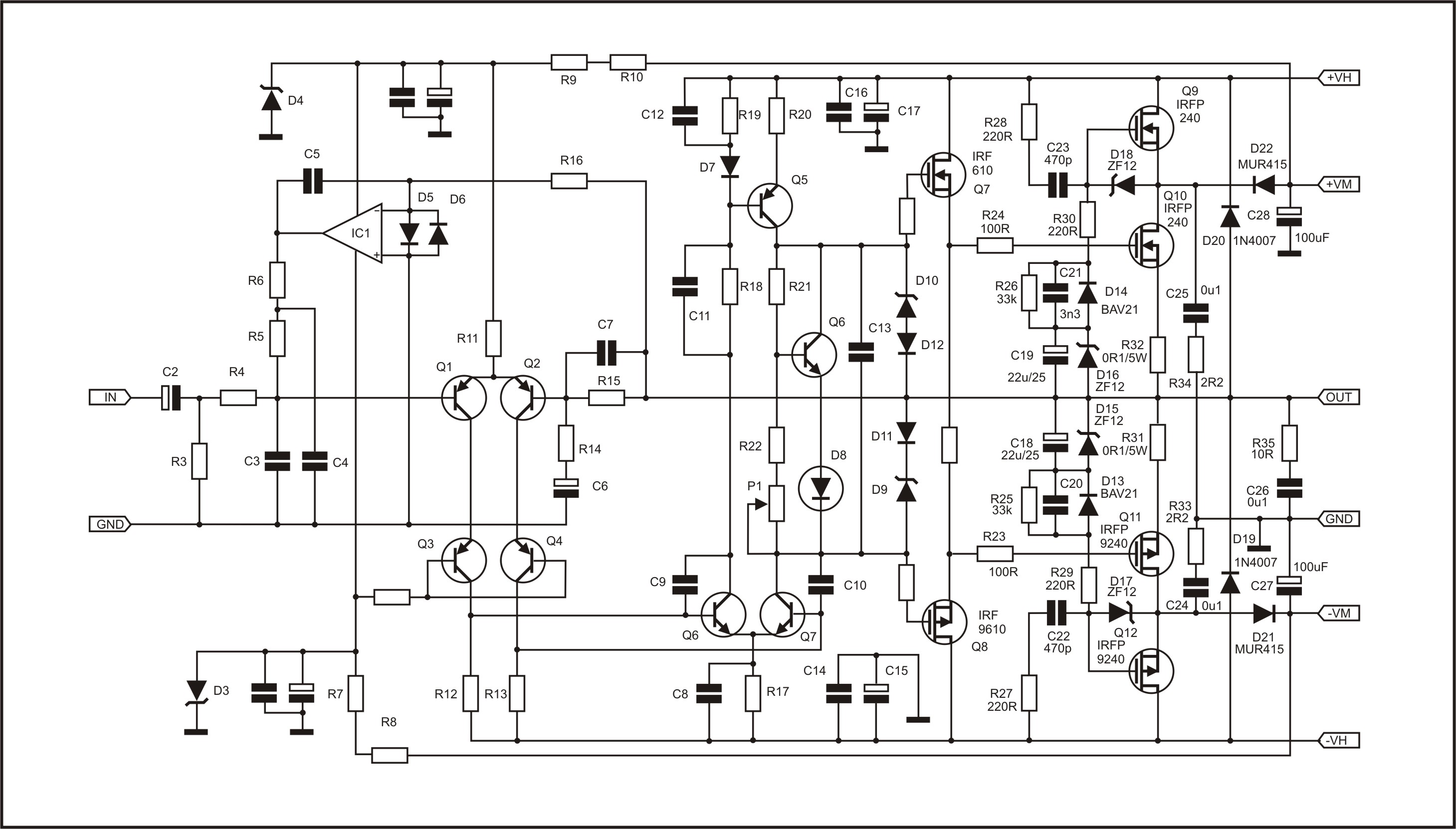
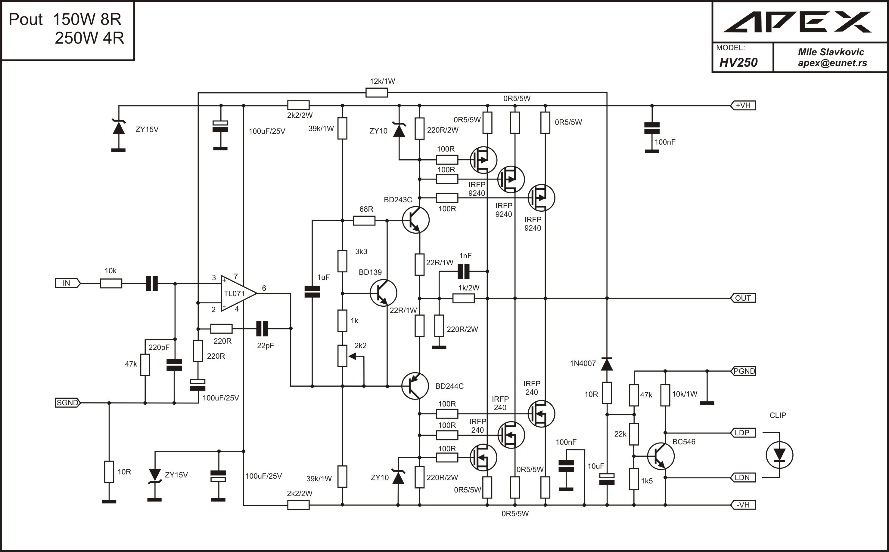
HV250 - added 6/7/2016:
553583d1465301961-directory-apex-audio-amplifiers-apex-hv250-sch.jpg


H900 (900w into 8R) Class H high power PA amp output stage for use with separate VAS stage - added 6/3/2016:
900W H-class PA Amp with Limiter

161327d1267886205-900w-h-class-pa-amp-limiter-apex-h900-output.jpg


More info on VAS stage and PCB here:
http://www.diyaudio.com/forums/solid-state/292226-directory-apex-audio-amplifiers-2.html#post4735042

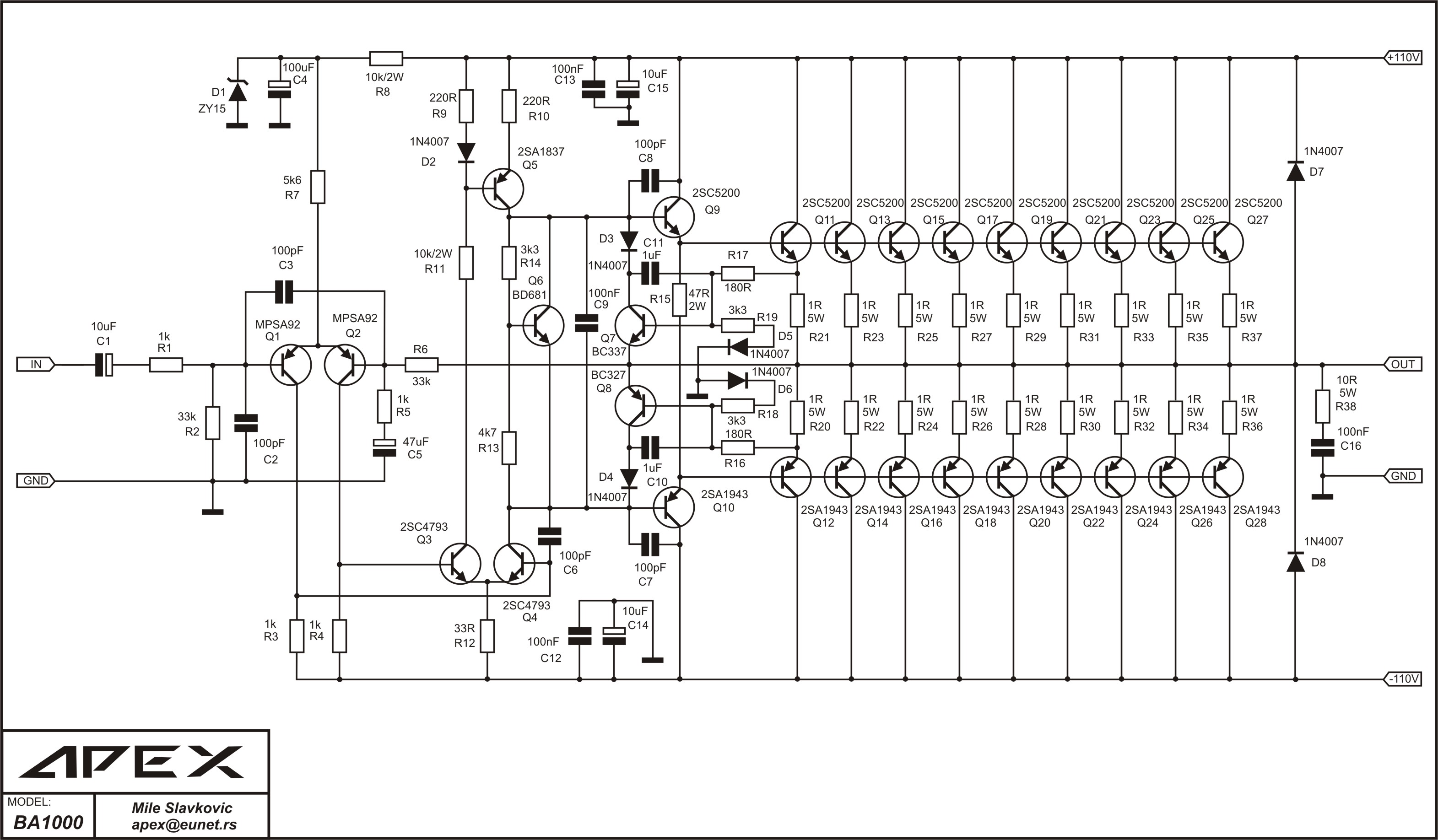
BA1000 (1000w into 8R pro sound amp) - added 6/7/2016:

http://www.diyaudio.com/forums/solid-state/292226-directory-apex-audio-amplifiers-2.html#post4738805

348292d1368399671-1000w-simple-pa-amplifier-apex-ba1000-sch.jpg


B2000 - added 6/15/2016:
554795d1465895287-directory-apex-audio-amplifiers-b2000-2.jpg
  • Like
Reactions: altec9440

Symptoms of overheating - Maida Regulator

I've built a version of Merlin's Maida HT Regulator + DC heater supply (schematic attached, featured in his hifi book) to power a little PCL82 SE stereo spud amp. I've tried to fit it all in to a small Hammond chassis, with some success. Except for when it's been running for a while...

For the 1st 20 or so minutes, mains hum is practically inaudible. Then it gets distractingly loud. I've yet to take measurements of the ripple or temperature, but the chassis is hot.

An early version of system had both U1 (an LM317) and Q2 (an IRF820) bolted to the chassis a couple of inches apart as in the attached picture. This was when I noticed the issue first - an intermittent 'put put put'ing every 20 seconds or so when the amp had been running for 20 / 30 mins. Not an oscillation, not at a constant 50 / 100 Hz. This, along with the awful ripple.

Thinking it was a thermal issue, I moved Q2 to the other side of the chassis, thinking the space / surface area might help things. I also then got my own PCBs made up with easier connection points. Replacing all components in the PS and starting afresh, things worked well - until it gets hot...

Would ripple increase if Q2 is overheating? Does this sound a purely thermal problem? Have I massively underestimated the cooling requirements and need to start drilling some air holes in the top?

Numbers:

I estimate the HT is supplying ~55mA at ~280Vdc. Heaters is 0.6A at 14Vdc. Transformer can supply 275-0-275 @ 120mA and 18Vac @3A. Some SPICE simulations indicate the MOSFET is dissipating <2.5W at these operating conditions, but that might be wrong.

I've had success with the same PS design in a preamp supplying 40mA at 280Vdc and 1A at 12Vdc. In this design Q2 had a small heatsink attached to it (venting to inside the chassis) and U1 was chassis mounted.

Attachments

  • Regulator.png
    Regulator.png
    210 KB · Views: 492
  • IMG_0289 (1).jpg
    IMG_0289 (1).jpg
    184 KB · Views: 494

Triple output linear supply

Hello people,

I'm working on basic LM317 linear supply and I'd like to output three different voltages:

V+/V- for the audio circuit and an extra V+ for LEDs, relays, etc...

Which of the two following diagrams would you recommend in terms of isolation, performance, etc?

Ideally, I'd like to use (B) as it's a simpler solution but I'd really appreciate your input!

Attachments

  • A.jpg
    A.jpg
    56.6 KB · Views: 175
  • B.png
    B.png
    53.8 KB · Views: 172

Firland Extreme 1200D output issue

Good day. I hope all is doing well on your repairs. I am working with a Firland Extreme 1200D mono amp. It had a blown 1 rail capacitor 1500uf /80v but i replaced all 6 of them, Power is normal . blue light and no protect issue but no audio output. I checked the output FEts IRF260M , 2 lows and 2 highs driven by one IRS214S and found out they switching is not normal. I removed all output FEts and the driver is producing good drive signal to gates of Low side. I fixed 2 FetS (1 low nand1 high) and the switching is normal on Hi and Lo. But when i fix all of the FEts it is not switching normally, some sort of noise in the signal and you can hear hissing sound only on the output. I replaced also the drive chip, checked the outout FETS are all good but stll same issue. Please refer to the Pictures. I checked all output components i believed are all good, Rail voltage is good as well at 114Vdc. It is frustrating sometimes that expecting a direct repair but its not even if you know that you are doing well on hours of repair ha ha. Did anyone encounter this issue?

Attachments

  • Firland 1200D.jpg
    Firland 1200D.jpg
    258.6 KB · Views: 89
  • FET Drain signal.jpg
    FET Drain signal.jpg
    132.8 KB · Views: 88

Passive crossover design

For a passive 12dB/octave resistor capacitor crossover for use between two tube stages how do I design it?

Is it select a resistor and capacitor value and multiply the result by 10? If so do I put the smaller value first or the larger value first?

I know for a high pass the capacitors go in series and for a low pass the resistors go in series.

I'll post the schematic of what is driving the filter and the stage after the filter later in the morning when I get to work.

Determination of 6s21p se amp opt impedance

Hello to All,
I want to build a single ended amp with 6p21s direct heated pentode tube. In triode mode, anode voltage 450V and current will be 40mA. What I know in practise, primary inductance of output transformer can be selected 2,5-3 times of tube internal resistance. But, it also depends the anode voltage. Anyone can help me to determine the suitable opt primary impedance for above given operating point?
Thank you so much!
Noyan

Attachments

  • IMG_9020.jpeg
    IMG_9020.jpeg
    248.9 KB · Views: 88
  • IMG_9018.jpeg
    IMG_9018.jpeg
    487.9 KB · Views: 84
  • IMG_9021.jpeg
    IMG_9021.jpeg
    310.1 KB · Views: 84

SQ CDT->ESS I2S DAC connection vs CDT->ESS DAC coaxial connection

I’ve got CEC CDT with I2S and coaxial outs. While standard I2S implementation utilizes 3 wires DATA, Clock and LR Clock, CEC adds fourth wire for master clock to run CDT/DAC in master/slave mode. According to reviews CEC CDT is supposed to produce better SQ with their own ESS DAC when I2S link is used.

When it comes to jitter I2S is supposed to be a better connection than coaxial but ASCR converter in ESS DAC supposed to reduce clock jitter by converting it into random noise so IS2 connection with ESS may be redundant when it comes to jitter.

I’ve got Octo DAC 8 which is ESS Sabre DAC but I can use it with CEC CDT only with coaxial connection. I wonder if it would be any audible difference if I replace my DAC with ESS CEC DAC and use IS2.

Sumo Athena schematic

In an old thread over the years a call for the schematic of the original Sumo Athena (not the mk-2) was made, without success:

A thorough review of the Sumo Athena was published in US-based magazine AUDIO of August 1989. See post 2 of member Hearinspace in:
including a close description of the functionality. But no schematics. The designer and founder of SUMO, Jim Borgiorno passed away in 2013.

So now, a re-newed request for the schematic.

Anyone?

Designing a motherboard to accommodate the T-Reg - please critique my design.

G'day Guys,

I am brewing up a dual mono Aikido preamp and I have reached the power supply stage.
I have a pair of T-Reg V4 boards to do the regulating duty.

So I need something to provide the unregulated B+ to the T-Regs.
Also I need something to provide a regulated DC heater supply.
For the sake of aesthetics, I would prefer an integrated solution rather than a bunch of separate boards all over the place.
I also don't like screw terminals so I had to come up with a solution to avoid using these on the T-reg

So what I have come up with is a 'motherboard' of sorts with a DC heater supply, B+ rectifier and RCRC filter, and a lovely spot in the middle to to affix the T-reg to.


So here we are:
V2.0 schematic.png
V2.0 Top.pngV2.0 Bot.png

A few highlights:
  • Pours for the high current DC heaters
  • 3 Element snubbers for the transformer secondaries (worked out with a quasimodo)
  • Hexfreds for the Mark Johnson approved 'belt and suspenders' approach to snubbing
  • 2.54mm pitch pin headers for connecting the T-Reg to the motherboard. I couldn't find any 5.08mm pitch pin headers so my plan is to use 3 pin headers and snip off the centre pin.
This is my first attempt at designing a high voltage PSU.
My power transformers have 230Vac secondaries for the B+ meaning something like 325Vdc raw B+.

Does anybody see anything obviously wrongheaded, dangerous, stupid or sub-optimal?

Small 3-way with KEF SP1632 & SB Acoustics

Hi everyone,

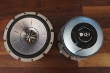
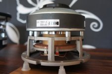
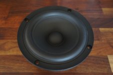
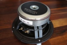
I’m currently working on a small 3-way based around the KEF SP1632 co-axial driver paired with dual SB Acoustics 5” mid-woofers.

The design is called Concentric Three – M5 and I thought I should share the construction progress for those who are interested.

The KEF SP1632 is a great sounding little driver with several nice features like a braced aluminium/magnesium mid-range cone for suppression of cone break-ups as well as a wave-guide like feature for the aluminium tweeter dome.

Here are more details on the construction as well as detailed measurements on the driver units:

Concentric Three – M5 Construction!
KEF SP1632 Measurements!
SB Acoustics SB15NRXC30-8 Measurements!

Note! The KEF SP1632 driver isn’t generally available to DIY:ers. Either it has to be stripped from a loudspeaker in the “R Series” or ordered as a spare part, but this requires a valid “R Series” serial number in order to be able to obtain the driver.


Regards

/Göran

Attachments

  • Picture1.jpg
    Picture1.jpg
    75.7 KB · Views: 1,177
  • Picture2.jpg
    Picture2.jpg
    75.1 KB · Views: 1,147
  • Picture3.jpg
    Picture3.jpg
    73.2 KB · Views: 1,087
  • Picture4.jpg
    Picture4.jpg
    79.5 KB · Views: 1,102
  • Picture5.jpg
    Picture5.jpg
    87.2 KB · Views: 1,080
  • Picture6.jpg
    Picture6.jpg
    82.6 KB · Views: 287
  • Picture7.jpg
    Picture7.jpg
    92.3 KB · Views: 362
  • Picture8.jpg
    Picture8.jpg
    89 KB · Views: 510
  • Picture9.jpg
    Picture9.jpg
    83.3 KB · Views: 489
  • Picture10.jpg
    Picture10.jpg
    87.7 KB · Views: 401

Burning Amplifier BA-2

Here it is! The new Burning Amplifier BA-2.

The Burning Amps are modular in that you choose a Gain Stage and an Output Stage to create the amp of your dreams.

The input "Gain Stage" section which increases the voltage can be used for any of the Burning Amps. The first gain stage is no longer in production, but the Second, confusingly called the BA-3 is available in the diyAudio Store.

So you can combine the gain stage with either one of two "Output Stages" which are also available in the Store.

One output stage is single ended and the combination with a gain stage is the BA-1 Amp. The output stage consists of 2 small PCB's and two longer ones.

One output stage is complementary and the combination with a gain stage is the BA-2 Amp. The output stage also consists of 2 small PCB's and two longer ones. but they are all different than the ones for the BA-1 output stage.

Single-ended amps are quite inefficient, and only operate in pure Class A. The are the Audiophile Purist choice and probably have a small sound quality advantage, depending on your preference.

Complementary amps are more efficient, and transition smoothly from pure Class A operation to Class AB when more power is required

The BA-2 is the second Nelson Pass design in the Burning Amp series. This one is a complementary output amp that uses much of the gain circuitry from the previous single ended BA-1.

I really enjoyed Nelson's detailed explanation of how it works, and how in even greater detail than before he answers the perennial questions "How hot is too hot?" "How to avoid a literal burning amp by firing it up correctly," and "How some design decisions affect the sound".

Finally, he gives us hints as to how the design can be adjusted and varied even by those of us who aren't experts. I'm getting all kinds of ideas and you will too. You don't need to have gotten a gift chassis from Nelson at the Burning Amp Festival in order to make a Burning Amp, just this article....

Mark

Aksa Lender P-mos Hybrid Aleph (ALPHA) Class A Amp GB

The technical discussion thread for the ALPHA amp is here:

Aksa Lender P-mos Hybrid Aleph (ALPHA) Amplifier

Thank you AKSA for design and inspiration, JPS64 for layout, and Nelson pass for Aleph CCS!

This is a spin-off from the above thread to keep discussions to the group buy and the build process separate.

Schematic for 20W ALPHA:
660029d1517503984-aksa-lender-mos-hybrid-aleph-alpha-amplifier-alpha-20w_schematic-v4-png


Parts placement:
660032d1517503984-aksa-lender-mos-hybrid-aleph-alpha-amplifier-alpha-20w_topview-png


3D render:
660030d1517503984-aksa-lender-mos-hybrid-aleph-alpha-amplifier-alpha-20w_3d_render-png


Example build with Vishay-Dale/Wima/Silmics:
666395d1520249706-aksa-lender-mos-hybrid-aleph-alpha-amplifier-alpha-premium-build-02-jpg


Another example with non-premium resistors:
661735d1518324741-aksa-lender-mos-hybrid-aleph-alpha-amplifier-alpha20-amp-build-02-left-jpg


Alpha 20 with 1.31amp bias and 2.86vrms into 8ohms gives 0.0069% THD, 0.0059% if using all Vishay-Dale:
661737d1518324741-aksa-lender-mos-hybrid-aleph-alpha-amplifier-alpha-20-2-87vrms-8ohms-fft-png


BOM and Schematics here (note that there is error on R108, should be 47R not 470R, and for R131 and R132, use Pan ERX 3W 0.47R and 0.22R, respectively for 1.35 amp bias:
http://www.diyaudio.com/forums/soli...rid-aleph-alpha-amplifier-51.html#post5348523

Corrections to previous BOM in BOLD
Feb. 20, 2018 v1
Position Mouser # Mfg # Product Description
R101 594-5063JD2K200FT MBA02040C2201FRP00 Metal Film Resistors - Through Hole .4watt 2.2Kohms 1% 1/8watt body size
R102 594-MRS16000C2202FRP MRS16000C2202FRP00 400 mW Thin Film Resistors 22Kohms 1% 50ppm
R103 594-MRS25000C3301FCT MRS25000C3301FCT00 Thin Film Resistors .6watt 3.3Kohms 1%
R104 594-MRS16000C6801FC1 MRS16000C6801FC100 400 mW Thin Film Resistors 6.8Kohm 1% 50ppm
R105 81-PV36Y202C01B00 PV36Y202C01B00 Trimmer Resistors - Through Hole 2.0Kohms 10mm Square 25turn
R106 594-5063JD220R0F MBA02040C2200FC100 Metal Film Resistors .4watt 220ohms 1% 1/8watt body size
R108 Metal Film Resistors .4watt 47ohms 1% 1/8watt body size
R111 594-5063JD820R0F MBA02040C8200FC100 Metal Film Resistors - Through Hole .4watt 820ohms 1% 1/8watt body size
R112 594-5063JD220K0F MBA02040C2203FC100 Metal Film Resistors .4watt 220Kohms 1% 1/8watt body size
R113 588-OK2235E-R52 OK2235E-R52 Carbon Film Resistors 22K Ohm 1/4W 5% 250 Volt (ok to use high quality Vishay-Dale 1% metal thin film here)
R121 *correction* 1k 1% metal thin film
R122 594-5063JD2K200F MBA02040C2201FC100 Metal Film Resistors .4watt 2.2Kohms 1% 1/8watt body size
R123 594-5063JD1K500FT MBA02040C1501FRP00 Metal Film Resistors - Through Hole .4watt 1.5Kohms 1% 1/8watt body size
R124 594-5063JD100K0FT MBA02040C1003FRP00 Metal Film Resistors .4watt 100Kohms 1% 1/8watt body size
R125 652-3296W-1-204LF 3296W-1-204LF Trimmer Resistors - Through Hole 3/8" 200Kohms Sealed Vertical Adjust
R126 594-5063JD220R0F MBA02040C2200FC100 Metal Film Resistors .4watt 220ohms 1% 1/8watt body size
R1270 81-PV36Y202C01B00 PV36Y202C01B00 Trimmer Resistors - Through Hole 2.0Kohms 10mm Square 25turn
R127 594-5063JD1K400F MBA02040C1401FC100 Metal Film Resistors .4watt 1.4Kohms 1% 1/8watt body size
R128 594-5063JD680R0F MBA02040C6800FC100 Metal Film Resistors .4watt 680ohms 1% 1/8watt body size
R129 594-5063JD220R0F MBA02040C2200FC100 Metal Film Resistors .4watt 220ohms 1% 1/8watt body size
R131 0.47ohms 3W Panasonic ERX
R132 0.22ohms 3W Panasonic ERX (or two 0.47R in parallel is ok too)
Do not use thick film metal oxide or inductive wirewound here
C101 505-FKP2D002201D00HA FKP2D002201D00HA00 FKP - Film Capacitors 220 pF 100 VDC 2.5%
C102 555-RFS35V100ME3#5 RFS-35V100ME3#5 Aluminum Electrolytic Capacitors - Leaded 10uF 35V 20% Audio SILMIC II
C103 *correction* use 470uF to 1000uF 35v is ok and no audio passes through this cap but large 1000uF prevents turn-on thump.
C1020 Bypass 871-B32523Q1225K B32523Q1225K000 22.5mm LS Film Capacitors 2.2uF 100volts 10%
C1020 (alternate) 75-MKP1848610914P2 MKP1848610914P2 Film Capacitors 10uF 1100volt 5% 2pin 37.5mm LS
C1021 80-PHE426HR8100JR6L2 PHE426HR8100JR06L2 Film Capacitors 250volts 10uF 5% LS 37.5mm
C1022 871-B32672P6105K B32672P6105K Film Capacitors 1.0uF 10% 630Vdc MKP PFC, LS 15MM
C105 581-12061A180FAT2A 12061A180FAT2A Multilayer Ceramic Capacitors MLCC - SMD/SMT 100V 18pF C0G 1206 1%
C111 555-RFS50V102MK9#5 RFS-50V102MK9#5 Aluminum Electrolytic Capacitors - Leaded 1000uF 50V 20% Audio SILMIC II
C112 505-MKP2J021001E00MS MKP2J021001E00MSSD Film Capacitors 0.01 uF 630 VDC 20%
C113 581-12061A180FAT2A 12061A180FAT2A Multilayer Ceramic Capacitors MLCC - SMD/SMT 100V 18pF C0G 1206 1%
C115 505-MKS2C041001FJC00 MKS2C041001F00JC00 Film Capacitors 1uF 63 Volts 5%
C121 505-MKS4C041002EKSSD MKS4C041002E00KSSD Film Capacitors 1uF 63 Volts 5%, 7.5mm Lead spacing
C122 647-UFG2A221MHM UFG2A221MHM Nichicon Aluminum Electrolytic Capacitors - Leaded 220uF 100 Volts 20% Tol.
C122 alternate 555-RFS35V221MI6#5 RFS-35V221MI6#5 Elna Simic II electrrolytic 220uF 35v
C128 647-UFG2A221MHM UFG2A221MHM Nichicon Aluminum Electrolytic Capacitors - Leaded 220uF 100 Volts 20% Tol.
C128 alternate 555-RFS35V221MI6#5 RFS-35V221MI6#5 Elna Simic II electrrolytic 220uF 35v
C127 505-MKS2C041001FJC00 MKS2C041001F00JC00 Film Capacitors 1uF 63 Volts 5%
V101 512-KSA992FBU KSA992FBU Bipolar Transistors - BJT PNP Epitaxial Sil
V102 512-KSA992FBU KSA992FBU Bipolar Transistors - BJT PNP Epitaxial Sil
V103 512-KSC1845FTA KSC1845FTA Bipolar Transistors - BJT NPN Epitaxial Sil
V121 512-BC547CBU BC547CBU Bipolar Transistors - BJT NPN 45V 100mA HFE/800 - TO-92-3
V131 844-IRFP240PBF IRFP240PBF MOSFET N-Chan 200V 20 Amp
V132 844-IRFP9240PBF IRFP9240PBF MOSFET P-Chan 200V 12 Amp
D035 78-1N4148 1N4148TR 500 mW Diodes - General Purpose, Power, Switching 100V Io/150mA T/R
X141, 142, 143, 144, 131, 132 534-1287 1287 Keystone Terminals .250" PCB TERMINAL
X101 571-3-641213-2 3-641213-2 TE Connectivity - Headers & Wire Housings POLARIZED HEADER 2P Straight Post gold

ALPHA 20 Group Buy PCBs are $28/pair with $5 shipping to USA, $10 to Canda, and $15 everywhere else.

Current list of GB2 for ALPHA 20:

danibosn - 2 sets
Yoaudio - 1 set
BRN - 1 set
pieter t - 1 set
danny_66 - 1 set
jvojvo - 1 set
postip - 1 set
tonza75 2 set
spind - 1 set
mk15 - 1 set
*** 52 Watt Version ***
Here is the 52W Big Boy (BB) version of ALPHA coming up soon. Waiting for beta test to verify functionality.
667515d1520672272-aksa-lender-mos-hybrid-aleph-alpha-amplifier-bb-1pn_pba-jpg


Edit April 4, 2018: as-built schematic for Alpha 20 for 1.35amp bias.

673097d1522861468-aksa-lender-mos-hybrid-aleph-alpha-amplifier-alpha-20-schematic-updates-1-35amps-built-png


Edit April 15, 2018: ALPHA BB GB is proceeding. Cost of 1 pair of 2mm thick FRP, 2oz copper, ENIG finish is $60. Shipping in US is $8, Canada is $17, everywhere else is $24 (10oz weight 240mm x 130mm size is expensive to ship).

Schematic for v2:
675435d1523845018-aksa-lender-mos-hybrid-aleph-alpha-amplifier-alpha-bb-production-schematic-v2-jpg


Parts placement for v2:
675436d1523845018-aksa-lender-mos-hybrid-aleph-alpha-amplifier-alpha-bb-production-top-view-placement-v2-jpg


BOM for v2 is here.

OP AMP maximum current draw on supply rail??

Help.
I am trying to determine the worst case power draw from the power rail for a OP07DP and a LM358AN. I have the data sheets for the parts but cant seem to find a definitive characteristic.
For the LM358AN I see the supply current | Icc MAX at infinite load (open) and Vcc=30V to be 2ma so 60mW.
For the OP07DP I see Power dissipation | Pd no load , Supply voltage +- 15V = 150 mW

The circuit is a simple split power supply transformer -> rectifier -> ~16Vdc -> current limit resister -> 7.5 zener -> limit resister -> 2.5V reference device.

I realize that there is more loading the 7.5V zener than the op amp supplies. In fact the entire operations of the 2.5V reference circuit.

These are the steps that I am taking to figure out the load on the power supply;
1. what is the maximum (worst case scenario) needed to run the op amps.
2. what is the load drawn from the 2.5V reference during normal operation plus some % head room.
3. select loading resister appropriately for that need.
4 model circuit and re adjust for increased efficiency of power supply.

*****In order to get past step one I need to know if I am reading the data sheets correctly to find the values I am looking for??

I am willing to do the leg work but can't seem to ask the right question when searching for information about how to read op amp data sheets.
I have watched what seems to be hours of vids and read a lot of information but I am only finding information that deals with ideal power supplies and ideal op amps. When I go the zener route I get lots of information about selecting current limiting resisters according to power need and load. Now I need to figure out the load.

Please Help

Thanks
Jeremy

Attachments

Is My New Looper Pedal Broken?

I got this simple looper pedal for Christmas: https://www.amazon.com/LEKATO-Synchronous-Recording-Function-Unlimited/dp/B094N3HNMV

I finally got to try it, and it records fine but when I start playing on top of the loop, the guitar is drowned by horrible noise like static, sounds like way overloaded. I... don't think it is supposed to do that. I first tried at the end of my (pretty small) pedal chain, then tried without anything: guitar -> looper -> mixer -> PA speaker. The same thing is going on albeit a bit less.

Should I return it (I still can or, more precisely, Santa can) or it is something I don't understand how to use? I did not think there was much room for error there but who knows.

4x Acrosound 6L6 ultralinear amplifiers

I have been collecting parts for this project for several years. It started when I went to the next town over with my friend, to look at some McIntosh 40s, which he bought and the seller tossed in 2 Heathkit Williamson amplifiers because I asked what he was going to do with em.
The McIntosh 40s are now rebuilt and he and his neighbors all love them!

I didn't want to build another Williamson amplifier with these because that's already been done, alot... luckily, within the Acrosound transformer catalog there's another schematic for a 6L6 amp using the TO-300. Perfect, I'll build the one that nobody else has done.

I started by slapping some parts I already had, together into a working prototype proof of concept. B+ was about 100v low. A few resistors were glossed together to make values, but once it worked it sounded good. Best of all the bass was tight and clear. Gotta have good tight clean bass.
At that point I made a list of the components I didn't have and got them coming from mouser. Just resistors and caps... I never ordered the chassis.
At that point the project languished while I got my 1972 toyota put back together and driveable. Now that it's going into amp building season again I've got them pulled back out and I'm making chips.
I ordered 4x 12x7x3 hammond boxes for chassis, I made 4 reinforcement struts out of 1.5" angle aluminum. I acquired 4 8 Henry, 150 miliamp chokes also from mouser. Drew it all out on graph paper and then transfered it to the chassis using a center punch. The chassis are all drilled out and finished now, the reinforcement struts are responsible for a lot in these amps, they keep the chassis rigid, but also provide a mounting point for terminal strips, and they act as a nut, meaning I tap holes in them so I don't need to use nuts on my hardware. The cathode resistor for the cathode biased output stage is attached directly to the strut with 4-40 stainless screws so the strut will act as a heat sink as well. There's also a row of convection holes which allow the heat to rise out of the chassis. Last night I began wiring up the first if 4. Yes there will be 4. Two are for me, and 2 are for my friend Izeck.
Because I'm weird, I like to style my builds to keep people guessing as to when the amplifier was put together. When it looks like I built something out of Radio and television news in 1956, I'll have reached my goal. Along those lines, I've decided to build these with octal sockets for a companion preamp, which were common back in the day. Preamps often robbed their miniscule power from the power amp they were driving. I'll set mine up to run my McIntosh C8, and C8s because that's what I've got. Reconfiguring the plug is simple and it has a rca in case you wanted to use some other self powered Preamp...
Overall very fun and relaxing experience and I'm not done yet. I'll try and get a photo of the schematic up today, it's a simple one, but I've never seen, much less heard one...

Questions comments?

I missed Burning amp this year but I'll bring these next year for sure.
20231002_075957.jpg
20231002_080006.jpg
20231002_193814.jpg
20231005_081516.jpg
20231006_074510.jpg
20231015_191552.jpg
20231019_185248.jpg
20231020_161740.jpg
20231020_161734.jpg
20231020_161737.jpg

Compression & horn addition to double 15" bass cabinet KCS C-215 for PA

Hi,
a friend of mine recently salvage some old pa speakers from a cinema.
He got two bass cabinets from spanish speakers cinema brand KCS : the c-215 model. It's your typical passive double ported 15" bass cab. Along with it came one subwoofer (a double 18"), and two amps.
The two bass speakers came without the compression + horn that is usually mounted to it (model is kcs s801 driver + s201 horn).

So we're looking about how we can get it all to work in order for us to have a small PA system.
Our objective is to organize small concerts / parties in the countryside. So a stereo system obviously. Music played is everything from indie rock to traditionnal music (think old instruments) during live shows, to electronic music of all genre during parties.
Mostly outside, some small indoors places as well, not attached to a fixed venue. We are not a professionnal operation, think non profit diy concerts parties, we'll book local acts and dj friends.

I'm here to get recommandations about which compression + horn might pair nicely with it for our use. There is'nt a lot of data on the cabinets sadly, the only figure i get is the crossover frequency is pretty low at about 500hz. Best would be to get some measurements done, which we will defintely do when we get around to it.
I'm struggling to identify compression drivers that go this low for pa use (the obvious solution would be to add another way between the bass and the compression, but lets not for the moment).
In addition we'll have to get some active filters, if anyone has a good recommendation for something that can be found secondhand. Otherwise we'll have to get some budget stuff like behringer to start, i'd prefer to put the money on some good drivers first.

Thank you for reading,

Attachments

  • KCS_S2501_1-4420e048.png
    KCS_S2501_1-4420e048.png
    151.2 KB · Views: 192

TDA7375 2.1 amp

Hi, I'm recycling some recycled material to build a small 2.1 amp for the desk. I will use a TDA7375 with a simple preamp input to have more gain for the phone. The proposed scheme contains a preamp based on TL072 and a filter for the subwoofer cut at around 100 Hz based on TL081. All powered at around 12V or maybe 15V. Being a beginner, can you give me directions and/or corrections, but above all would it work?
tda7375a.jpg
  • Like
Reactions: cush man

Books for "Sale"

I am reducing my books/references collection with an aim to supporting DIY Audio by "auctioning" them, with the agreed-upon sale price and shipping to be paid directly to DIY Audio Store. I am doing this to support this forum and the Store, to avoid having to deal with money, and to ensure that there is no question that "sale" proceeds will go directly to DIY Audio Store. US sales only, as shipping would be prohibitive to foreign countries.

The books available are:
  • Electronic Products for Guitar, RA Penfold (PC Publishing), softback perfect bound)
  • Vacuum Tube Guitar and Bass Amplifier Servicing, Tino Zottola (The Bold Strummer Ltd, 1995)
  • The Williamson Amplifier, Articles from "Wireless World," reprinted by Audio Amateur Press/Old Colony Sound, softback
  • RCA Receiving Tube Manual, RC-20, softback perfect bound
  • RCA Transmitting Tubes, Tecnical Manual TT-5, softback perfect bound
  • An Approach to Audio Frequency Amplifier Design: Seventeen Circuits from 5- to 100- watts, The General Electric Co. of England, reprinted by Audio Amateur Press, softback perfect bound
  • Valves for Audio Frequency Amplifiers With Full Details for Building Eight Circuits, E. Rodenhis, Phillips Technical Library, reprinted by Audio Amateur Press, softback perfect bound
Post what book you want and your bid (not a PM). I plan to ship via book rate, unless you want me to use a USPS priority flat rate envelope which includes insurance.

To maximize the possible amount to be contributed to DIY Audio Store, I will hold the "auction" open for 10 days. Once that is closed, I will contact you and work out payment and shipping.

Please help me support the DIY Audio Store!

Karlson

-kinda made fun of them - until I actually heard one's awesome dynamics and got to know them a bit better - I've owned Transtatics, Maggies, Tympani 1D, Edgarhorn, Acoustat, Klipschorns and piles of boxes - Karlson have been the most fun and most powerful sounding for their size.

An externally hosted image should be here but it was not working when we last tested it.

An externally hosted image should be here but it was not working when we last tested it.

An externally hosted image should be here but it was not working when we last tested it.

An externally hosted image should be here but it was not working when we last tested it.

An externally hosted image should be here but it was not working when we last tested it.

An externally hosted image should be here but it was not working when we last tested it.

An externally hosted image should be here but it was not working when we last tested it.

An externally hosted image should be here but it was not working when we last tested it.

An externally hosted image should be here but it was not working when we last tested it.

An externally hosted image should be here but it was not working when we last tested it.

An externally hosted image should be here but it was not working when we last tested it.

Borbely Millenium 200 - Monoblocks PCB Set, all assembled and tested, optional Transformer

Hi. I have too many amplifiers, these ones have to go. They are the complete PCB sets to build the Borbely Millenium 200 Mono-block amplifiers, all assembled and tested with the two main supply big, large power 120000uF caps. You just need to mount them into the proper chassis to have some of the best amplifier ever made...

All PCB are very high quality, designed and made by me, 2oz copper, and much better than the original Borbely standard ones, with hi quality parts (Caddock MK132 & MP9100 and PRP resistors, Black Gate, MultiCap, Silmic and Cerafine capacitors, etc, only the best). Check the pictures, I includes some pictures of my test prototype where I tested the amp pcb.

If you are interested I can also sell you the pair of very high quality, custom made, potted 1KVA Plitron power transformers. They are dual 115V primaries, and support 115-120 or 220-230V international AC supplies. The internal power supply used for the Front end and protection can also be selected from 115 or 230V, so these amps can be used in Europe or in other foreign countries without problem.

The amp has soft start and output protection circuit, ground lift circuit (can be bypass by switch), AC input DC filter, Output Mute timer, discrete HexFRED 600V, 25A rectifiers, high capacity supply filter United Chemicon 120000uF, 63V, KMH Series caps. The front end, fully discrete used the famous J74/K170 matched JFET input and the J313/K2013 driver MOSFET and also for the discrete regulators (yes, Borbely was in advance to Pass at the time 😉), and the final is using matched set of 2SK1058/2SJ162. The main amp front end pcb has also the latest discrete regulator Cascode bias mods done.

I made an extra set of PCB with two AMGIS potted toroid to supply the front end independently of the final.The final PCB was designed in two half PCB, so you can mount each polarity on its own heatsink, doubling the original design heatsink surface, so you can crank the bias even more. One of my friend did that with great result. It is up to you, one single or dual heatsink...

The amp has balanced and SE input.

Just in parts they costed me 1500$CAN per monoblock with the custom Plitron transformers... Total of 3000$CAN

So I'm asking a fair price of 1000U$ for the complete parts kit, excluding the custom Plitron transformers, plus shipping and 3.5% Paypal fee (or use friend and family).

Today the amps would cost at least 4k$-5K$ to build, if you can find the parts...

If you want the pair of 1KVA Plitron transformer, let me know, keep in mind they are large and heavy, shipping will be expensive!, I can discuss the total price accordingly.

The kit will come with extensive documentation, original Borbely docs, all PCB schematics and pcb silkscreen, detailed BOM and I'll help you if you have any question. This is not a beginner project, but an expert one. All PCB are tested and certified to work, but it is a high power, high current and rather high voltage amplifier. You need to know what you're doing working around this beast...

This kit was designed to be my reference amplifier, no expenses was spared to build it, but sadly I'm not in a different place and the kit has to go.

I'm open to fair offers, but sorry I won't give away the kit for free 😉 Hope you understand.

SB

Attachments

  • Img_7665.jpg
    Img_7665.jpg
    191.4 KB · Views: 480
  • Img_7664.jpg
    Img_7664.jpg
    162.6 KB · Views: 481
  • Img_7666.jpg
    Img_7666.jpg
    180.2 KB · Views: 476
  • Main_Both.JPG
    Main_Both.JPG
    127.5 KB · Views: 480
  • Caps_Bypass.JPG
    Caps_Bypass.JPG
    161.8 KB · Views: 453
  • Borbely_Proto2.JPG
    Borbely_Proto2.JPG
    66.4 KB · Views: 435
  • Transfo_44V_Main-PCB.jpg
    Transfo_44V_Main-PCB.jpg
    177.9 KB · Views: 436
  • Borbely_1KVA_Transformer.jpg
    Borbely_1KVA_Transformer.jpg
    85.8 KB · Views: 344

Rod Elliot 101 Lateral MOSFET help

Hello,

I've recently recieved Rod Elliots amplifer board from the 101 project, which is a Lateral MOSFET design. If anyone has experience with building his amplifiers, I have a question about the source resistors R12, R13, R16 and R17. I can't seem to find the ones he recommends in his design. But I have a pretty close match, 0.11 ohms lower to be exact. Also his are rated at 2W and mine are rated at 5W. Could I use these resistors instead?

If you bought any of his boards you will know the actual values, if not you probably can't help me.

Thank you for your help.

Attachments

  • Screenshot_20210616-124134_Chrome.jpg
    Screenshot_20210616-124134_Chrome.jpg
    90 KB · Views: 507

Retired old tech

I'm on AudioKarma also.
The last couple of years I've been restoring old electronics -turntables, Heathkit instruments, tube AA5 radios. Zenith, RCA, Wards, GE.
A few multi-band (ZTO, RTO) a few TV's and maybe a Kurzweil.
But recently focused on tube receivers. So far restored three Sherwood S8000's.
I had rather poor schooling, but I manage.
I like to rock.

Which Nelson design has most transparent HF?

Hello friends,

I need a very specific criteria meeting design which would most importantly optimize for these parameters:

1. Extreme high frequency clarity, airiness, whatever you want to call it. I want most importantly the extremest version in terms of fidelity. When the high frequencies have intensity and bite, like electric guitars have intensity and bite or most any mental strings or cymbals, small bells etc. but I don't want that to come with the cost of harshness. So extremely intense with non-smothered transients, but smooth and perhaps even warm at the same time. Energetic! Or maybe forget all that, what I am looking for is the most "musical" and "magical" amplifier in terms of the high frequency character.
2. I don't care about power output, it can be anything from 2 to 30 Watts.
3. I don't care how efficient it is or how much power it consumes even 300W is fine if that'll improve the sound.
4. I don't care about bass performance more or less.
5. Preferably as simple a design as possible with as few stages as possible.
6. Only single ended class A with only N channel MOSFETs as the output stage unless that would limit the criteria above.
(7.) Balanced would be a plus, but completely tertiary in importance.


I've been reading for the past days about the different Nelson's designs. There's just an insane amount to learn and on top of that, I have no listening experience to any of them, hence I come to you to seek guidance.

If I understood it correctly, the Zen variants although the most simple, do not offer the same high frequency clarity as Aleph or F series.

Are active current source designs mostly made for reducing the negative effects that low frequency signals cause in terms of voltage swings at the output mosfet collector? Would it be wise to avoid active current source design (I intend to build very capable and clean PSU anyway) if I am not going to play any bass frequencies or alternatively use the amplifier for high impedance low current loads like planar magnetic headphones? The main purpose of the amplifier would be to drive either passive speakers at low volumes or the JBL JT025TI1-4 tweeter from ~1.6kHz-20kHz in an active system. Am I correct to assume that the lower input capacitance MOSFETs would be the best for my application. Many people have good words to say about the Exicons, but they are high power application designs. Any recommendation in terms of exact MOSFETs to use? How about voltage? I don't care about how much power it dissipates, but would higher current, lower load resistance work better for me or high voltage, higher load resistance?

Any insight in what designs and what series of Nelson's designs would be the most relevant to me, would be much appreciated. Any comments, just anything you could say if you have experience with any of it. And especially listening experience comparing the different models. But also, any design experience or understanding of how the different design choices would affect the outcomes I'm looking for. Or just general familiarity with Nelson's designs, and guidance in regards to them, would be amazing.

Old Sennheiser FM wireless Noise Issue with Soundcraft Digital Mixer

I wanted a set of wireless headphones for "IEM" duty in my home studio. Minimal SQ; just need to hear myself play and sing, with the mixers effects. One less cord to trip over is always welcome. So I picked up a set of the OLD FM wireless Sennheisers for a song off epay. They work / sound just fine for the intended purpose, driven by a portable digital player or connected to my laptop PC.

I chopped the two RCA plugs and wired up a 1/4 TRS to match the Soundcrafts headphone jack and plugged in the Sennheiser wireless. It sounds like white noise is loudly mixed in with the audio signal. Of course, with the wired phones, the Soundcraft UI 24R's headphone output has no such aberration; its clear as a bell.

Ah, must be some digital hash is coming out the Soundcraft UI 24R's headphone output! So I dug up a hollow ferrite slug originally intended for a power line conducted emissions suppression, and redid the TRS plug soldering after winding 3 turns of the line cable through it. No joy, it's not going to give it to me that easily.

I have a set of microphone balanced input transformers I ripped out of a Behringer mixer. Same Z on both windings I believe. Do I have a chance at blocking whatever it is upsetting the Sennheiser by placing these in the line going to it, as an isolation attempt?

It's amazing how inanimate objects can "conspire" to thwart the one simple thing I want to do. Or at least put up a good fight.

For Sale 4 TOKIN 2SK180

Up for are sale are 4 2SK180. I was planning to use them in a DIY amp build but since it hasn't happened yet it's time to let someone else put them to use. I have no idea how well they match and I want to sell them as a set.

How about $240 US + shipping from Canada for the 4.

Please note that even though these are NOS they are being sold AS IS with no returns and I'm limiting the sale to NA only.

Thanks for looking and happy holidays!

1734858595825.png
  • Like
Reactions: birdbox

Is butterworth filter good for audio?

Hi, i'm having some doubts on what kind of filter to use for audio and on if i made them right.

I need those filters in a preamplifier.

I designed three band pass filters:

1)30 - 125Hz (Subwoofer)
2)125 - 4000Hz (Midrange)
3)4000 - 20000Hz (Tweeter)

I designed them to be butterworth filters, but are they actually good for audio applications or they introduce too much distortion?

Every stage of the BPF is actually a 4th order filter. A 4th order HPF connected to a 4th order LPF.

For example, the first 30 - 125Hz BPF is made out of a 4th order 30Hz butterworth HPF connected to a 4th order 125Hz butterworth LPF.

Also, i decided to use a buffer OpAmp between the HPF and the LPF.
Is it going to make a difference or it's useless?

Is this going to work or it is better to change topology?

Here i posted a schematic that i found on the internet. It's 4th order butterworth LPF.
Imagine my design as one of those connected to another one of those but with the resistors and capacitors swapped (HPF). (Of course the two resistors for setting the gain are always in the same spot).

So, by swapping the resistors with the capacitors and the capacitors with the resistors, will it become a HIGH PASS filter with the same cutoff frequency formula, or the formula for calculating the cutoff frequency changes?

I mean, the formula for calculating the cutoff frequency for both LPF and HPF is the same?

I used this formula for designing both HPF and LPF:

Fc = 1 / (2 * 3.14 * R * C).

This is because the two filter resistors are the same value and same for the two capacitors. 3.14 of course is pi, i dont know how to type it.

Is this the right formula?

I also followed the rule that the first stage of a fourth order butterworth filter has to have a gain of around 0.152 and the second stage has to have a gain of around 1.234.
So both combined will have a gain of around 2.57.

This is only for a single LPF / HPF 4th order stage though.
So i think the total gain of a complete BPF is 2.57 * 2. (Because it's 4th order HPF + 4th order LPF combined).
Is this right?

For the best accuracy i'm going to use ±0.1% resistors and all capacitors are polypropilene for best audio performance.

But before placing the order, i wanted to ask...
Did I make some mistakes or those filters are going to work fine?

I'm basically a newbie in this kind of stuff, and this is a personal project.
I'm sorry if i made a lot of mistakes that might be ovbious to you.

If you need more information than what i provided for now, no problem at all, i will provide them.

Attachments

  • Screenshot_2024_0813_001839.jpg
    Screenshot_2024_0813_001839.jpg
    31.2 KB · Views: 208

Help me build a PA system on a tight budget

Hello everyone, I need your help with some decisions about a pub I'm thinking about opening and I'm trying to make the best decisions according to my limited budget.
Mind you this will be a small space, about 650 sq ft (60 sq meters for us Europeans) and that the used market for PA equipment in Europe is quite limited.

My signal chain will be laptop<DJ controller<dsp/mixer<amp<speakers

I'm starting from the bottom up.

-Speakers will be something diy like the Redcatt Kellerkind,96 db efficiency,12 inch woofer (130€ per speaker) (https://oaudio.de/?a=24802&lang=eng) .I can build my own speakers.

-Amp will be something like a Crown XLS 1502 for the two speakers and I'll add another 1502 for a sub later (440€). Down the road I might add 2 more speakers like the ones I mentioned.

-Dsp will be a t.racks DSP 4x4 mini or a Behringer mixer (120€)

-DJ controller will be something like a Numark Mixtrack Platinum FX (270€)

Do you have any better suggestions for the prices?I'm not looking for the best hifi result, just something that will be above average from the rest of the shops here (cheap amps from the 80's,bad speaker placement,clipping at moderate levels, multiple underpowered/cheap speakers etc).
Given the size of the shop is quite small,I don't think I'll need an overkill of speakers/amps. Am I wrong?
I will be putting everything together by myself so if I'm missing something please feel free to correct me.


Thank you in advance!

Studio 350 construction thread

Hi every one

Please find my build thread of my studio 350 power amplifier; I will post various pics of the build through the stages to final completion.
I have taken feedback from my other builds to include all through holes use grommets and all high voltage areas sleeved and double insulated etc.

An externally hosted image should be here but it was not working when we last tested it.


the tiger is my motif (jamesfeline) and the eyes light up when the amplifier is on, newer designs will include the option that they change colour when the amplifier gets hot.

An externally hosted image should be here but it was not working when we last tested it.


An externally hosted image should be here but it was not working when we last tested it.


The above pic shows my power control module, this contains all the various fuses and the delay antisurge board for the transformer. The pcb is copper claded underneath and earthed etc.

An externally hosted image should be here but it was not working when we last tested it.


The above pic shows the modded velleman speaker protection module, this area has been modded since this photo, I will upload the new pics tonight

An externally hosted image should be here but it was not working when we last tested it.


The above pic shows the main power amp pcb being offered into postion, also only showing one main psu cap at the moment, this version of the studio 350 will be a light version as I started to run out of room for every thing. The transformers is 500va .. at a later date I will make a full blown version if I am happy with the sound of this one

I will upload some more photos tonight

regards]

Nick

Limiter Rod Elliot

Hi, this circuit adds hum to the signal chain:

p92-f3.gif

I don't quite understand how VTR1 controls the limiter sensitivity, but if it is not shorted (reducing NFB to 1k) it adds audible hum.
Quite a lot at end position.

Even at min setting, if I take out the limiter pcb and bypass the signal, there is less hum.

I am examining my pcb and connection for ground loops, but why it adds hum at relatively small gain (up to gain 10 I think)

Hello

I'm from Malaysia and I just want to share something in this thread:

I'm still listening on this "Chinese DAC".
Excellent? I don't know the measurements but I like the sound.
But too bad the SPDIF only can do 88.2KHz max and the USB only can do 48KHz max; how I wish it can do at least 96KHz.


Dual TDA1305T with CS8412 SPDIF and CM108B USB


The DAC board


I am using it with SMSL PO100 DDC


And powered by 5V 20F super capacitor power filter

Distortion measurements on loudspeakers _ do they tell anything of value?

Good morning everyone
I have always read with great interest and tried to understand the lab reports showing the results of measurements carried out on loudspeakers
With reference to the distortion parameter I see different approaches:

1) those who make measurements
2) those who make measurements but remain doubtful about their importance
3) those who do not make measurements at all and never discuss the topic

I wanted to have some advice on the subject Some opinions
Lately I saw a video of an old Infinity Renaissance series loudspeaker that I liked mainly for its form factor
I found praise online with reference to its remarkable sound quality
But I also found an old review in Italian magazine that confirms the excellent sound quality but caused me some doubts
https://www.audioreview.it/prove/diffusori/infinity-renaissance-90.html
In essence this magazine has developed a test in which is reported the max SPL at one meter obtainable at various frequencies with intermodulation distortion not exceeding 5%
Unfortunately the procedure is not clear
The graph that comes out (see below ) is quite disappointing especially at low frequencies even if a special woofer is used

1736178446868.png


Can graphs like this be useful?
If so, why are they an exception rather than a rule?

Sound tracks to testing midrange

Good morning everyone!
I'll start by saying that I'm sure that the problem has already been discussed and I ask you to direct me the link to the specific thread
The subject is music tracks useful for judging a cone midrange driver and I would say of various sizes
maybe already with low and high cuts to avoid distortion and breakups

I recently read that since the ear is more sensitive in the mid frequencies, the voice is a difficult instrument to reproduce, some designers use recordings of voices to select their midrange drivers
Then I noticed something. By a twist of fate, the drums also play in the same range as the voice You can see very different requirements
So using only recordings of voices is a rather huge mistake
I'll make it short I think I would use tracks like this one instead
with both voices and drums If they will sound good it will mean they are good

Login to view embedded media

Construction of slot port

Hi everyone

I'm building a two way system with a 12" Faital Pro bass and a horn sitting on top. For the cabinet for the bass, I'm doing a 100L enclosure with a slot port.
I'm a bit in doubt how to proceed with the slot port both regarding design and construction.

If I build the slot port in the front, my idea was to cut a hole in the front plate and building a box to glue on the backside. In this design, I assume the port also needs some kind of bracing below to support the weight?

The side port seems easier to make as I will simply just add another plate inside the cabinet.

Any thoughts?

Thanks!!

Attachments

  • Screenshot 2025-01-10 at 16.20.36.png
    Screenshot 2025-01-10 at 16.20.36.png
    838.5 KB · Views: 98
  • Screenshot 2025-01-10 at 16.25.54.png
    Screenshot 2025-01-10 at 16.25.54.png
    410.4 KB · Views: 95
  • Screenshot 2025-01-10 at 16.26.26.png
    Screenshot 2025-01-10 at 16.26.26.png
    293.8 KB · Views: 110

Help with Kaisui CD Player

Hello,

I have just bought a cheap Kaisui KR341 cd player from vinted because I love to tinker with stuff. I am trying to find a schematic as I want to remove the display and buttons and replace the buttons. I have worked out the play, stop and open/close buttons but am struggling to understand the prev and next. Any help would be appreciated.

Edit - Just realised they use the same pin and the resistance changes the action of the button press. Might as well delete or lock this now.

Belated introduction

Hello all, I’m belatedly posting an introduction despite having joined years ago. In the meantime I’ve come here often to read and learn - many thanks to members who have provided helpful information and guidance!

I became fascinated with audio in my teens and built my first speakers at that time with the help of my carpenter & joiner grandfather and his workshop. I know he was pleased to be able to share some of his skills and time with me.

Since then I’ve remained interested audio and in DIY repairs, especially of speakers, but any time it renews the usefulness of a quality product. Often this serves as an interesting challenge that also provides a learning opportunity. Add in some good music and what a great hobby this is!

I’m beginning to dabble a bit more in speaker design lately, now with the benefit of much more sophisticated tools, parts and access to info than when I was younger!
  • Like
Reactions: stv and krivium

Bose Wave DAB module problem BBC

A friend has owned a Bose Wave with a DAB module for 20ish yaers. Recently when listening to dab radio on BBC stations 2,4 and 6 the sound switches on and off constantly. About 1 second intervals and consistent across these stations. Other stations work fine or have burbling from a weak signal. The radio has been in the same place for years with no nearby changes. I've moved it around her home with no improvement. No faults at local transmitters. Any thoughts? Is this a signal problem or an electrical, software or hardware fault?

The Making Of Turntable Belts


Good evening all,

I have begun to give some thought to experimenting with making turntable belts. My DIY turntable uses a heavy platter with massive bearing. So far I've tried rubber belts but want to try other material. I have been checking out the Teres turntable and not that they have used various materials to drive their heavy platters. My platter weighs about 15 pounds which is not light.

I was looking at starting with "leader tape" but note that is does not seem to be sticky enough. I would think that platter slippage would be a problem with this material. Any thoughts from those of you who have gone down this road? Thanks for all comments.

Bob🙂

DIY Turntable belts.. How??

Guys,
Does anyone know how to make a turntable belt?
I'm trying to figure out what materials I can use and how to actually make it (searches on the internet find nothing other than "replacing" belts).

To give you some info: I am using a Pro-ject Genie motor and an acrylic platter made for the genie (acrylteller).
However, the distance between motor and platter are currently quite a bit more than on the genie, so I cannot use the genie's belt.
Projects by fanatics, for fanatics
Get answers and advice for everyone wanting to learn the art of audio.
Join the Community
508,469
Members
7,921,028
Messages

Filter

Forum Statistics

Threads
407,835
Messages
7,921,028
Members
508,469
Latest member
SpaceEsel