Is my Cambridge Audio Alva Duo the weak link?
- By Borats Baby
- Analogue Source
- 4 Replies
Hi.
Can I give you my story for context.
Equipment :
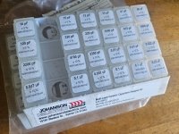
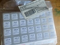
Project 1 X-pression with carbon arm and Ortofon 2M black.
Cambridge Audio Alva Duo
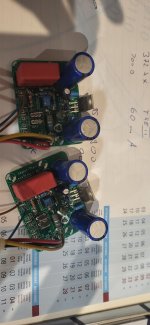
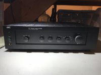
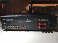
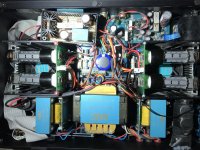
CR developments Kalypso PP EL84
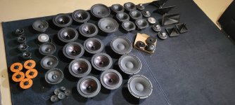
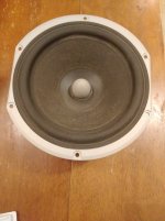
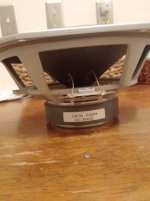
FHXL / Mark Audio MAOP10
The whole system apart from the turntable is fairly new to me and I'm still getting used to it.
I'd had a 2M Bronze for about 4 or 5 years and had a feeling the stylus might be worn, hence the 2M Black. Records seemed to play ok, but were lacking a bit of sparkle. The top end definitely sounded rolled off.
Anyway, after fitting the 2M Black, I was still underwhelmed with vinyl replay..
Now, my digital source is also new to me and is a wiim pro.
I've been messing with the EQ etc simply because it's there, and found the sound I like has that "smiley face" shape on the sliders, with more emphasis on the top end. The FHXL's are quite bass heavy.
So.....
Can I do better than the Cambridge Audio phono stage?
Is it a weak link?
As always, any advice appreciated.. Further info available upon request lol..
Can I give you my story for context.
Equipment :
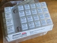
Project 1 X-pression with carbon arm and Ortofon 2M black.
Cambridge Audio Alva Duo
CR developments Kalypso PP EL84
FHXL / Mark Audio MAOP10
The whole system apart from the turntable is fairly new to me and I'm still getting used to it.
I'd had a 2M Bronze for about 4 or 5 years and had a feeling the stylus might be worn, hence the 2M Black. Records seemed to play ok, but were lacking a bit of sparkle. The top end definitely sounded rolled off.
Anyway, after fitting the 2M Black, I was still underwhelmed with vinyl replay..
Now, my digital source is also new to me and is a wiim pro.
I've been messing with the EQ etc simply because it's there, and found the sound I like has that "smiley face" shape on the sliders, with more emphasis on the top end. The FHXL's are quite bass heavy.
So.....
Can I do better than the Cambridge Audio phono stage?
Is it a weak link?
As always, any advice appreciated.. Further info available upon request lol..