This a new thread originated from the Haudegen thread . The initial design evolved on so many and different ways that a split was necessary to keep the overview what's cooking here ")
Before we can dig any deeper I need to summarise all the info that is used in HtBs Oread.
Firstly some placeholders will be put in here.
Depending on the spare time - have kids they said, it will be fun they said! - the blanks are filled.
The spec goals:
Some general thoughts:
Any help and suggestions are more than welcome to achieve a proper enjoyable circuit for everyone.
Depending on the interest a group buy for PCBs could be initiated - but firstly we need to check the schematics/datasheets/simulation and do a nice test build with real world measurements.
I guess till end of this year we do some brain work and after the dust of xmas-warfare cleared up
we can freshly heat up our soldering irons and have some fun in the analogue world.
Before we can dig any deeper I need to summarise all the info that is used in HtBs Oread.
Firstly some placeholders will be put in here.
Depending on the spare time - have kids they said, it will be fun they said! - the blanks are filled.
The spec goals:
- MM phono amplifier
- Gain: <xxdb>
- exp. THD <>
- discrete only
- RIAA implemented in negative feedback
- RIAA tolerance <xx%>
- economic friendly (no OOP parts included)
- proper PSU design
- more TBD!
Some general thoughts:
Any help and suggestions are more than welcome to achieve a proper enjoyable circuit for everyone.
Depending on the interest a group buy for PCBs could be initiated - but firstly we need to check the schematics/datasheets/simulation and do a nice test build with real world measurements.
I guess till end of this year we do some brain work and after the dust of xmas-warfare cleared up
we can freshly heat up our soldering irons and have some fun in the analogue world.

Hi, As far as I can see, the "mirror" performance will be depending on supply voltage and stability. Why not use a conventional mirror with identical resistors and an additional diode or diode-coupled transistor?
Current in input stage with about 0.5mA transistors seems high and will probably by generate current noise with MM pickups. It's about double what NAD uses with similar input stage based on 2SC1815L transistors and 3 times what they use with 2SB737 transistors.
Consider splitting the (currently 8.2K) tail resistor in two (1K and 7.5K if staying with 0.5mA/transistor). Put the 1K closest to the positive supply and decouple the center point to gnd with a capacitor.
Thank you "LJT",
I ask myself all these questions again and again - surprisingly, exactly this discrete OP works very well. The idea behind the split-off project is the following: to use as few components as possible and at the same time not to simply copy one of the known circuits. I wouldn't even want to call the "1k2, PNP, 560 Ohm" node a current mirror. 2 * 500µA in the input pair is a lot, of course you are right - and I am glad that you recognized this right away.
Based on the promising simulation and the experience already gained with this discrete OP approach, I would simply test it in real life.
If necessary, the 8k2 can be split on the object itself, which is no problem at all. Of cource the operating voltage must be perfect and constant, as you said, the behavior depends on it.
But this thread should be moderated by "Chestnutspread", I think he is open to further suggestions.
I suggest to stay with a maximum of five transistors - this should be used to build an Op-amp, with it an AllInOne-equalization must be realized.
You could also simply state that my quick suggestion reflects the principle of Oread. The component dimensioning and selection is still completely free - as I understand the thread creator.
At the end of the day, the result should be a replica-proof EQ for MM systems - no worse than the ones that are currently popular.
HBt.
Compromises
The interesting thing about the rocky road is the learning curve.
Not only do you have to understand and grasp the circuit, you also have to choose the right components. Then there's the dimensioning and other design issues.
A headroom of at least 6 dB, preferably 10 dB - but we won't quite be able to achieve that with 18 V (+/-9 V). Nevertheless, in the very worst case we are not worse than 6 dB - never.
The open loop gain is clear, at least 80dB, otherwise we'll have to tinker with the time constants and make do with a slightly lower output level.
But the other big problem (apart from the THD footprint) is noise. It might turn out that we should double R1=8k2 (8k2 + 8k2 plus decoupling, as "LJT" suggested). With 2 * 250µA the noise figure decreases.
And that of course entails further adjustments ... (Headphones, an oscilloscope, a multimeter, a breadboard ... and the DIY fun can begin).
HBt.
Last edited:
Noise is not always the same
If there really is a problem due to the 2*500µA in the input pair, but I don't want to change this quiescent current, then I have to split it up.
Maybe the 1/f-noise changes, but the shot noise of the base current stays the same as long as the sum of the base currents stays the same.
Many thanks for the tip Marcel.
Are you familiar with the 1982 SUPRA design (from Elektor)? I don't remember there being any problems there - 2 * (2 * 320µA), distributed over 8 PNPs and 8 NPNs in the symmetrical configuration.
I would like to measure and listen immediately, but my employer ticks differently. I'm curious to see if it works and if the noise (regardless of type) will be negligible.
For fun, I'll attach another sketch.
Attachments
Why not?
Let's just go for it, nineteen transistors per channel - |333µA| each in the second stage, that shouldn't generate any problems ...
Dear Chestnutspread,
I don't want to hijack your thread - how do you like the development? All still theoretical and seemingly intuitive, just like in the Haudegen thread.
Bye,
HBt.
Attachments
thermal noise, path resistances, pn transitions, shot noise, sparkle noise, popcorn noise
Generally speaking, if the collector current is less than or equal to 100µA, you can expect a low noise figure.
The noise power here is due to different physical relationships, of course heat, but also currents. We define currents as charge carriers in motion, but the transport does not occur like a water jet. It's better to think of trickling sand grains, and it is precisely the irregularities that generate what we call noise.
The noise voltage of an ohmic resistor is the easiest to calculate, but for the bipolar transistor it is almost as easy using a corresponding equivalent circuit diagram.
We can therefore predict fairly accurately whether noise will be a problem for the range of small currents. Some experts claim that all bipolar transistors behave in the same way and that there are no special low noise transistors. They are also of the opinion that the parallel connection is useless with identical total current. This means that there is no change compared to the single transistor.
But the collector base capacitance will change - and we may not like that. If we could assume that everything is phase-locked, then we would achieve more disadvantages than advantages.
However, if we can assume that the substitute sources formed do not correlate, the addition should lead us to a reduction in the total noise power.
This is the usual hope and tenor. If this turns out to be nonsense, then we start all over again.
Somehow this is exactly the right thread to design a simple, discrete op-amp that serves as the basis for an MM EQ. Without frills.
Concrete suggestions or dimensioning are welcome.
Good night,
HBt.
Getting back to transistors in parallel:
There are various things going on in a transistor that generate noise. Assuming you use transistors with low 1/f-noise, so that we can forget about that, and that you bias them in the forward active region, but nowhere near to VCEO, what you are still left with are:
Collector shot noise. It behaves as if there is a random current source between collector and emitter with an RMS value of √(2qIC∆f) measured over a bandwidth ∆f, q is the elementary charge. For noise calculations, it is often convenient to transform it to equivalent sources at the input: you can transform it into an equivalent voltage source in series with the base with a value of (√(2qIC∆f))/gm, where gm is the transconductance of the transistor, and an equivalent current source between base and emitter that turns out to be negligible compared to the base shot noise as long as the frequencies are much lower than fT/√hFE, which they always are in audio circuits.
Base shot noise. It behaves as if there is a random current source between base and emitter with an RMS value of √(2qIB∆f) measured over a bandwidth ∆f.
Base spreading resistance thermal noise. The resistivity of the base material has thermal noise associated with it. The most convenient way to model it, is with a voltage source of √(4kTrb'b∆f) in series with the base, where k is Boltzmann's constant (1.380649 ● 10-23 J/K), T the absolute temperature and rb'b the base spreading resistance.
Now suppose that instead of using one transistor you use four in parallel. The collector shot noise sources are then in parallel. You can add the currents of current sources in parallel, but as the currents are independent random variables, you have to add their mean-square values (~= variances) rather than their RMS values (~= standard deviations). That is, the total RMS collector shot noise is √4 = 2 times as large as that of a single transistor. As the transconductance of the four transistors together is 4 times the transconductance of each separate transistor, the contribution of the collector shot noise to the equivalent input noise voltage is 2/4 times what it would be with a single transistor. So far, so good.
Unfortunately, the base shot noise sources are also in parallel. As the four transistors generate noise independently, the base shot noise current sources also have to be added in mean-square value, so the total RMS base shot noise is √4 = 2 times as large as that of a single transistor. It's already at the input, so it doesn't need to be transformed anywhere (this is actually a slight simplification).
I don't know how to explain in text what happens with base spreading resistance thermal noise, but when you do the correct noise transformations, it turns out that it halves when four transistors are put in parallel.
If you had just used one transistor and biased it at four times the current, that is, at the same current as all four in parallel, its RMS collector shot noise would also have doubled, its transconductance would also have quadrupled, the collector shot noise transformed back to the input would therefore also have halved and the RMS base shot noise would also have doubled. The only advantage left, is the reduced base spreading resistance thermal noise.
Mind you, I neglected 1/f-noise. I'm not sure what happens with 1/f-noise. For MOSFETs and on-chip resistors, it gets better with increased area, so I wouldn't be surprised if it also did get better when you effectively quadruple the area of a bipolar transistor by connecting four in parallel.
Last edited:
You can see from the equations in the previous post that there must be an optimum: equivalent at the input, the noise voltage goes down with increasing collector current, but the noise current goes up with increasing base current. As increasing or decreasing the collector current also increases or decreases the base current, there must be some value where the total noise is minimal.
Noise optimization of moving-magnet amplifiers is too complicated a subject to cover in a diyAudio post, but you can read my opinion about it here: "Noise and moving-magnet cartridges", Electronics World October 2003, pages 38...43, https://worldradiohistory.com/UK/Wireless-World/00s/Electronics-World-2003-10-S-OCR.pdf Mind you, Electronics World drew one of the sections of the gain switch in the wrong state in figure 5 and I mixed up the terms spectral density and power spectral density. I later extended the calculations to other noise weightings. The 3852 Hz becomes 5179 Hz when you prefer ITU-R 468 weighting, see Linear Audio volume 8, September 2014, https://linearaudio.nl/grammophone-preamplifier-noise-calculations-3852-hz-rule-revisited (behind a paywall).
The 51.56 μA I calculated for a bipolar transistor with hFE = 600 and a 500 mH cartridge is for a single transistor, not for a differential pair. In a differential pair (a normal one, not one that is as asymmetrical as the one I used), both transistors contribute to the noise voltage, which therefore gets √2 times as large. You have to increase the current per transistor by a factor of √2 to correct for this, so the optimal collector current becomes about 72.92 μA per side, total tail current 146.1 μA. That's also the optimum sum of the emitter currents through all the transistors when you use multiple differential pairs in parallel, or a differential pair made with multiple transistors in parallel, provided hFE stays 600 and the assumed cartridge impedance is correct.
That's the optimum, another question is what happens when you are not precisely in the optimum. Noise increases, but quite slowly.
Suppose that, for simplicity, you want to realize the 47 kΩ input resistance by simply connecting a 47 kΩ resistor across the input. That resistor will then contribute about 0.5869 pA/√Hz of noise current when its temperature is 20 °C. If base shot noise is allowed to contribute as much as the resistor, that requirement is met as long as the base current of the input transistor (or of all the input transistors together, if you use several of them) stays below 1.075 μA. With hFE = 600, that corresponds to 645 μA per side, tail current 1.292 mA.
Record surface noise is not included yet. If you only care about the noise with a record playing, and only look at the integrated noise and don't care about changes in the sound of the noise, then you can go much further from the optimum.
Last edited:
Reminds me circuit called SUPRA. There should be thread somewhereWhy not?
Let's just go for it, nineteen transistors per channel - |333µA| each in the second stage, that shouldn't generate any problems ...
Dear Chestnutspread,
I don't want to hijack your thread - how do you like the development? All still theoretical and seemingly intuitive, just like in the Haudegen thread.
Bye,
HBt.
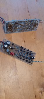
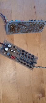
I have to make a confession, since 1992 I have been listening exclusively with MC systems, i.e. all my own designs are made for this type of generator. Maybe it's time to turn to MM /MD again?
In any case, I have an original SUPRA in my collection - and that's probably the reason why every parallel connection of bipolars immediately reminds me of this 1982 project.
But "Chestnutspread s OREAD" will not be a SUPRA
In any case, I have an original SUPRA in my collection - and that's probably the reason why every parallel connection of bipolars immediately reminds me of this 1982 project.
But "Chestnutspread s OREAD" will not be a SUPRA
Attachments
Many thanks Marcel,
I know your article on the subject - it's great that you have briefly touched on the subject here.
If you have a component suggestion and a dimensioning ready, the author of the thread will certainly be pleased (even if he is currently offline), I think at least.
The original idea was:
Just reach into the standard component box and get started, realize a simple and uncomplicated circuit.
Step two would be the evaluation; intuition first (I concede that you shouldn't be totally wrong, at all.)
Bye,
HBt.
- Home
- Source & Line
- Analogue Source
- Oread - a DIY MM phono approach